

Page 1
OmegaPAT XA
MI 3360
Instruction manual
Ver. 1.2.2, Code no. 20 752 658
Page 2

Mark on your equipment certifies that it meets European Union requirements for EMC,
LVD, ROHS regulations
Distributor:
Manufacturer:
Metrel d.d.
Ljubljanska cesta 77
SI-1354 Horjul
E-mail: metrel@metrel.si
http://www.metrel.si
© 2017 Metrel
The trade names Metrel, Smartec, Eurotest, Autosequence are trademarks registered or
pending in Europe and other countries
No part of this publication may be reproduced or utilized in any form or by any means without
permission in writing from METREL.
2
Page 3

MI 3360 OmegaPAT XA Table of contents
TABLE OF CONTENTS
1 General description ........................................................................................................... 7
1.1 Warnings and notes ........................................................................................................ 7
1.1.1 Safety warnings ...................................................................................................... 7
1.1.2 Warnings related to safety of measurement functions .......................................... 8
1.1.2.1 Flash HV ............................................................................................................. 8
1.1.2.2 Differential leak., Ipe leak., Touch leak., Ileak (W-PE), Primary leak., Power,
Leak’s & Power, Equipment leak., Applied part leak.__ .................................................... 8
1.1.2.3 Insulation resistance........................................................................................... 8
1.1.3 Markings on the instrument .................................................................................... 8
1.2 Power management ....................................................................................................... 9
1.2.1 230 V / 110 V operation .......................................................................................... 9
1.2.2 Battery and charging, auto power off ..................................................................... 9
1.2.3 Power Off, Restart .................................................................................................. 9
1.3 Standards applied ........................................................................................................... 9
2 Instrument set and accessories ..................................................................................... 11
2.1 Standard set of the instrument ..................................................................................... 11
2.2 Optional accessories .................................................................................................... 11
3 Instrument description .................................................................................................... 12
3.1 Front panel .................................................................................................................... 12
4 Instrument operation ....................................................................................................... 14
4.1 General meaning of keys.............................................................................................. 14
4.2 General meaning of touch gestures ............................................................................. 14
4.3 Virtual keyboard ............................................................................................................ 15
4.4 Safety checks ............................................................................................................... 15
4.5 Symbols and messages ............................................................................................... 16
4.6 Instrument main menu .................................................................................................. 20
4.7 General settings ............................................................................................................ 21
4.7.1 Language .............................................................................................................. 22
4.7.2 Date and time ....................................................................................................... 22
4.7.3 Profiles .................................................................................................................. 22
4.7.4 Workspace Manager ............................................................................................ 22
4.7.5 Auto Sequence® groups ...................................................................................... 22
4.7.6 Settings ................................................................................................................. 23
4.7.7 Initial Settings ....................................................................................................... 24
4.7.8 About ..................................................................................................................... 24
4.7.9 User Accounts ...................................................................................................... 25
4.7.9.1 Signing in .......................................................................................................... 25
4.7.9.2 Changing user password, signing out .............................................................. 26
4.7.9.3 Managing accounts .......................................................................................... 27
4.8 Devices ......................................................................................................................... 29
4.9 Instrument profiles ........................................................................................................ 30
4.10 Workspace Manager .................................................................................................... 31
4.10.1 Workspaces and Exports...................................................................................... 31
4.10.2 Workspace Manager main menu ......................................................................... 31
4.10.2.1 Operations with Workspaces ........................................................................... 32
4.10.2.2 Operations with Exports ................................................................................... 33
4.10.2.3 Adding a new Workspace ................................................................................ 33
4.10.2.4 Opening a Workspace ...................................................................................... 34
3
Page 4

MI 3360 OmegaPAT XA Table of contents
4.10.2.5 Deleting a Workspace / Export ........................................................................ 34
4.10.2.6 Importing a Workspace .................................................................................... 35
4.10.2.7 Exporting a Workspace .................................................................................... 36
4.11 Auto Sequence® groups .............................................................................................. 37
4.11.1 Auto Sequence® groups menu ............................................................................ 37
4.11.1.1 Operations in Auto Sequence® groups menu ................................................. 38
4.11.1.2 Selecting a list of Auto Sequences® ................................................................ 38
4.11.1.3 Deleting a list of Auto Sequences® ................................................................. 39
5 Memory Organizer ........................................................................................................... 40
5.1 Memory Organizer menu .............................................................................................. 40
5.1.1 Measurement statuses ......................................................................................... 40
5.1.2 Structure Objects .................................................................................................. 41
5.1.2.1 Measurement status indication under the Structure object ............................. 41
5.1.3 Selecting an active Workspace in Memory Organizer ......................................... 42
5.1.4 Adding Nodes in Memory Organizer .................................................................... 43
5.1.5 Operations in Tree Menu ...................................................................................... 44
5.1.5.1 Operations on measurements (finished or empty measurements) ................. 44
5.1.5.2 Operations on Structure objects ...................................................................... 45
5.1.5.3 View / Edit parameters and attachments of a Structure object ....................... 47
5.1.5.4 Add a new Structure Object ............................................................................. 49
5.1.5.5 Add a new measurement ................................................................................. 51
5.1.5.6 Clone a Structure object ................................................................................... 53
5.1.5.7 Clone a measurement ...................................................................................... 54
5.1.5.8 Copy & Paste a Structure object ...................................................................... 54
5.1.5.9 Copy & Paste a measurement ......................................................................... 56
5.1.5.10 Delete a Structure object .................................................................................. 57
5.1.5.11 Delete a measurement ..................................................................................... 57
5.1.5.12 Rename a Structure object .............................................................................. 58
5.1.5.13 Recall and Retest selected measurement ....................................................... 59
5.1.6 Searching in Memory Organizer........................................................................... 60
6 Single tests ....................................................................................................................... 63
6.1 Selection modes ........................................................................................................... 63
6.1.1 Single test screens ............................................................................................... 64
6.1.1.1 Single test start screen ..................................................................................... 65
6.1.1.2 Setting parameters and limits of single tests ................................................... 66
6.1.1.3 Single test screen during test ........................................................................... 67
6.1.1.4 Single test result screen ................................................................................... 68
6.1.1.5 Single test memory screen............................................................................... 69
6.1.2 Single test (inspection) screens ........................................................................... 70
6.1.2.1 Single test (inspection) start screen ................................................................. 70
6.1.2.2 Single test (Inspection) screen during test ...................................................... 71
6.1.2.3 Single test (Inspection) result screen ............................................................... 72
6.1.2.4 Single test (inspection) memory screen........................................................... 73
6.1.3 Help screens ......................................................................................................... 74
6.2 Single test measurements ............................................................................................ 75
6.2.1 Visual inspection ................................................................................................... 75
6.2.2 Continuity // Protective earth resistance .............................................................. 76
6.2.2.1 Compensation of test lead / IEC test cable resistance .................................... 78
6.2.3 Flash test .............................................................................................................. 79
6.2.4 Insulation resistance (Riso, Riso-S) ..................................................................... 81
6.2.5 Sub-leakage (Isub, Isub-S) ................................................................................... 82
6.2.6 Differential Leakage .............................................................................................. 84
6.2.7 Ipe Leakage .......................................................................................................... 86
4
Page 5

MI 3360 OmegaPAT XA Table of contents
6.2.8 Touch Leakage ..................................................................................................... 87
6.2.9 Power .................................................................................................................... 89
6.2.10 Leak's & Power ..................................................................................................... 90
6.2.11 PRCD test ............................................................................................................. 91
6.2.12 RCD test ............................................................................................................... 93
6.2.13 PE conductor (PRCD) .......................................................................................... 95
6.2.14 Open conductor (PRCD) ...................................................................................... 96
6.2.15 PRCD PE probe test ............................................................................................. 97
6.2.16 Polarity .................................................................................................................. 99
6.2.17 Clamp current ..................................................................................................... 101
6.2.18 Insulation resistance – Riso (welding equipment) ............................................. 103
6.2.19 Welding Circuit Leakage – I leak (W-PE) ........................................................... 104
6.2.20 Primary Leakage................................................................................................. 105
6.2.21 No-load voltage ................................................................................................... 106
6.2.22 Insulation resistance – Riso (medical equipment) ............................................. 107
6.2.23 Equipment Leakage (medical equipment) ......................................................... 110
6.2.24 Applied Part Leakage (medical equipment) ....................................................... 113
6.2.25 Touch Current (medical equipment) ................................................................... 115
6.2.26 Functional test .................................................................................................... 117
7 Auto Sequences® .......................................................................................................... 118
7.1 Selection of Auto Sequences® .................................................................................. 118
7.1.1 Selecting an active Auto Sequence® group in Auto Sequences® menu .......... 118
7.1.2 Searching in Auto Sequences® menu ............................................................... 119
7.1.3 Organization of Auto Sequences® in Auto Sequences® menu ........................ 121
7.2 Organization of an Auto Sequence®.......................................................................... 122
7.2.1 Auto Sequence® view menu .............................................................................. 122
7.2.1.1 Auto Sequence® view menu (Header is selected) ........................................ 122
7.2.1.2 Auto Sequence® view menu (measurement is selected) ............................. 123
7.2.1.3 Indication of Loops ......................................................................................... 124
7.2.1.4 Managing multiple points ............................................................................... 124
7.2.2 Step by step execution of Auto Sequences® .................................................... 124
7.2.3 Auto Sequence® result screen .......................................................................... 126
7.2.4 Auto Sequence® memory screen ...................................................................... 128
7.2.5 Print label menu .................................................................................................. 129
8 Maintenance ................................................................................................................... 130
8.1 Periodic calibration ..................................................................................................... 130
8.2 Fuses .......................................................................................................................... 130
8.3 Service ........................................................................................................................ 130
8.4 Cleaning ...................................................................................................................... 130
9 Communications ............................................................................................................ 131
9.1 USB and RS232 communication with PC .................................................................. 131
9.2 Bluetooth communication ........................................................................................... 131
9.3 Bluetooth communication with printers and scanners ............................................... 132
9.4 RS232 communication with other external devices ................................................... 132
9.5 Connections to test adapters ...................................................................................... 132
9.5.1 Active 3 Phase Adapter /Plus (A 1322 / A 1422) ............................................... 132
9.5.2 110 V Test Adapter (A 1474) .............................................................................. 133
10 Technical specifications ............................................................................................... 134
10.1 Continuity // Protective earth resistance .................................................................... 134
10.2 Insulation Resistance (Riso, Riso-S) .......................................................................... 134
10.3 Sub-Leakage Current, Substitute Leakage Current - S ............................................. 135
5
Page 6

MI 3360 OmegaPAT XA Table of contents
10.4 Differential Leakage current ....................................................................................... 135
10.5 PE leakage current ..................................................................................................... 135
10.6 Touch leakage current ................................................................................................ 136
10.7 Power .......................................................................................................................... 136
10.8 Leak’s & Power ........................................................................................................... 137
10.9 PRCD test ................................................................................................................... 139
10.10 RCD test ..................................................................................................................... 139
10.11 PE conductor (PRCD) ................................................................................................ 140
10.12 Open conductor (PRCD) ............................................................................................ 140
10.13 PRCD PE probe test ................................................................................................... 140
10.14 Polarity ........................................................................................................................ 141
10.15 Clamp current ............................................................................................................. 141
10.16 Flash test .................................................................................................................... 141
10.17 Insulation resistance Riso (welding equipment) ........................................................ 142
10.18 Welding Circuit leakage (Ileak W-PE) ........................................................................ 142
10.19 Primary Leakage (I diff) .............................................................................................. 142
10.20 No-load voltage ........................................................................................................... 142
10.21 Insulation Resistance (medical equipment) ............................................................... 143
10.22 Equipment leakage ..................................................................................................... 143
10.23 Applied Part leakage .................................................................................................. 144
10.24 Touch current (medical equipment) ........................................................................... 144
10.25 General data ............................................................................................................... 145
Appendix A Structure objects in OmegaPAT XA ............................................................ 146
Appendix B Profile Notes ................................................................................................... 147
Appendix C Print labels and write / read RFID / NFC tags ............................................. 148
C.1 PAT tag format ............................................................................................................ 148
C.2 Generic tag format ...................................................................................................... 150
Appendix D Default list of Auto Sequences® .................................................................. 152
Appendix E Programming of Auto Sequences® on Metrel ES Manager ......................... 153
E.1 Auto Sequence® Editor workspace ........................................................................... 153
E.2 Managing groups of Auto Sequences® ..................................................................... 154
E.2.1 Auto Sequence® Name, Description and Image editing ................................... 156
E.2.2 Search within selected Auto Sequence® group ................................................ 157
E.3 Elements of an Auto Sequence® ............................................................................... 158
E.3.1 Auto Sequence® steps ....................................................................................... 158
E.3.2 Single tests ......................................................................................................... 158
E.3.3 Flow commands .................................................................................................. 158
E.3.4 Number of measurement steps .......................................................................... 158
E.4 Creating / modifying an Auto Sequence® .................................................................. 158
E.5 Description of flow commands ................................................................................... 159
E.6 Custom Inspections programming ............................................................................. 162
E.6.1 Creating and editing Custom Inspections .......................................................... 162
E.6.2 Applying Custom Inspections ............................................................................. 164
6
Page 7

MI 3360 OmegaPAT XA General description
Read before use
1 General description
1.1 Warnings and notes
1.1.1 Safety warnings
In order to reach high level of operator safety while carrying out various measurements using
the OmegaPAT XA instrument, as well as to keep the test equipment undamaged, it is
necessary to consider the following general warnings:
Read this user manual carefully, otherwise use of the instrument may be
dangerous for the operator, for the instrument or for the equipment under test!
Consider warning markings on the instrument!
If the test equipment is used in manner not specified in this user manual the
protection provided by the equipment may be impaired!
Do not use the instrument and accessories if any damage is noticed!
Regularly check the instrument and accessories for correct functioning to avoid
hazard that could occur from misleading results.
Consider all generally known precautions in order to avoid risk of electric shock
while dealing with hazardous voltages!
Use only standard or optional test accessories supplied by your distributor!
Only test equipment provided or approved by Metrel should be connected to 3-
PHASE ADAPTER connector.
Do not connect external voltage to CLAMP inputs. It is intended only for
connection of Clamps approved by Metrel.
Use only earthed mains outlets to supply the instrument!
If working on other than 230 V TN/TT voltage systems refer to chapter 1.2.1 230 V /
110 V operation.
In case a fuse has blown refer to chapter 8.2 Fuses to replace it!
Instrument servicing and calibration is allowed to be carried out only by a
competent authorized person!
LCD screenshots in this document are informative only. Screens on the
instrument may be slightly different.
7
Page 8
MI 3360 OmegaPAT XA General description
1.1.2 Warnings related to safety of measurement functions
1.1.2.1 Flash HV
A voltage of up to 3 kV
between main socket’s LN and PE socket terminals / 1.5 kVAC between FLASH and
mains socket PE terminal is applied to the instrument’s outputs during the test.
Although the current of the HV source is limited to safe level special safety
consideration must be taken when performing this test!
between FLASH and mains socket LN terminals / 1.5 kVAC
AC
1.1.2.2 Differential leak., Ipe leak., Touch leak., Ileak (W-PE), Primary leak., Power, Leak’s & Power, Equipment leak., Applied part leak.__
Load currents higher than 10 A can result in high temperatures of fuse holders! It is
advisable not to run tested devices with load currents above 10 A for more than 15
minutes. Recovery period for cooling is required before proceeding with tests!
Maximum intermittent duty cycle for measurements with load currents higher than 10
A is 50 %.
1.1.2.3 Insulation resistance
Do not touch the test object during the measurement or before it is fully discharged!
Risk of electric shock!
1.1.3 Markings on the instrument
Read the Instruction manual with special care to safety operation«. The
symbol requires an action!
Dangerous high voltage is present on terminals during the test.
Consider all precautions in order to avoid risk of electric shock.
Mark on your equipment certifies that it meets European Union
requirements for EMC, LVD, and ROHS regulations.
This equipment should be recycled as electronic waste.
8
Page 9

MI 3360 OmegaPAT XA General description
1.2 Power management
1.2.1 230 V / 110 V operation
The instrument works on 110 V and 230 V mains. 110 V and 230 V appliances can be fully
tested.
In UK and Aus/Nz models only 110 V mains voltage will be applied to the mains test socket if
the 110 V test adapter (A 1474) is connected to the instrument.
1.2.2 Battery and charging, auto power off
The instrument has an in-built rechargeable battery pack. The battery is charged whenever the
instrument is connected to the mains. When the instrument is disconnected from mains, the
battery provides power to the instrument to stay energized for 1 minute. This is indicated by the
battery symbol in the upper right corner of the LCD. Operation with the instrument is not
possible except the mains was disconnected during the RCD test. As long as the instrument is
energized it will be ready to use immediately after connected to mains voltage again. This
enables faster testing of appliances.
If the instrument is not reconnected to mains within 1 minute it will completely switch off. When
connected to mains again, a normal power up procedure will be taken.
Figure 1.1: Indication of battery status
Notes:
A flat or faulty battery will result in an immediate power off after the instrument is
disconnected from the mains.
Charging time of the battery is about 14 h.
1.2.3 Power Off, Restart
Instrument is powered by battery:
when pressing the ESC key for ca 5 s the instrument will switch off.
Instrument is connected to mains:
when pressing the ESC key for ca 5 s the instrument will restart.
1.3 Standards applied
The OmegaPAT XA instrument is manufactured and tested according to the following
regulations, listed below.
9
Page 10

MI 3360 OmegaPAT XA General description
EN 61326-1
Electrical equipment for measurement, control and laboratory use - EMC
requirements – Part 1: General requirements
Class B (Portable equipment used in controlled EM environments)
EN 61010-1
Safety requirements for electrical equipment for measurement, control, and
laboratory use – Part 1: General requirements
EN 61010-2-030
Safety requirements for electrical equipment for measurement, control and
laboratory use – Part 2-030: Particular requirements for testing and
measuring circuits
EN 61010-031
Safety requirements for electrical equipment for measurement, control and
laboratory use – Part 031: Safety requirements for hand-held probe
assemblies for electrical measurement and test
EN 61010-2-032
Safety requirements for electrical equipment for measurement, control and
laboratory use – Part 2-032: Particular requirements for hand-held and
hand-manipulated current sensors for electrical test and measurement
EN 61557
Electrical safety in low voltage distribution systems up to 1 000 V a.c. and 1
500 V d.c. – Equipment for testing, measuring or monitoring of protective
measures
Instrument complies with all relevant parts of EN 61557 standards.
Code of Practice
Household and similar electrical appliances
VDE 0701-702
Inspection after repair, modification of electrical appliances – Periodic
inspection on electrical appliances
General requirements for electrical safety
IEC/EN 60974-4
Arc welding equipment – Part 4: Periodic inspection and testing
IEC/EN 62353
Medical electrical equipment - Recurrent test and test after repair of
medical electrical equipment
AS/NZS 3760
In-service safety inspection and testing of electrical equipment
Electromagnetic compatibility (EMC)
Safety (LVD)
Functionality
10
Page 11

MI 3360 OmegaPAT XA Instrument set and accessories
2 Instrument set and accessories
2.1 Standard set of the instrument
Instrument MI 3360 OmegaPAT XA
Bag for accessories
Flash test probe (MI 3360 F only)
IEC test cable 3 x 1.5 mm2, 2 m
Test lead (black)
Test tip (black)
Alligator clip (black)
Mains cable, 3 x 1.5 mm2, 2 m
USB cable
Calibration Certificate
Short form instruction manual
CD with instruction manual (full version) and PC SW Metrel ES Manager
2.2 Optional accessories
See the attached sheet for a list of optional accessories that are available on request from your
distributor.
11
Page 12
MI 3360 OmegaPAT XA Instrument description
3 Instrument description
3.1 Front panel
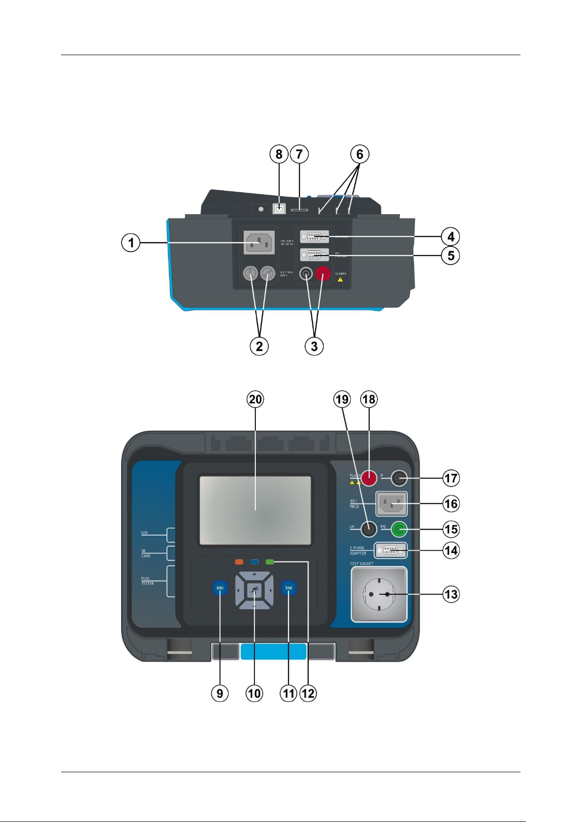
Figure 3.1: Left side panel
Figure 3.2: Front panel
12
Page 13

MI 3360 OmegaPAT XA Instrument description
1
Mains supply connector
2
F1, F2 fuses (T 16 A / 250 V)
3
Clamp inputs
4
Barcode scanner and RFID / NFC reader / writer device serial port
5
PC / Printer serial port
6
Fuse checker
7
MicroSD card slot
8
USB communication port
9
Escape key / reset key
10
Keypad
11
TAB key
12
Shortcut keys
13
Mains test socket
14
Data connection 3 phase adapter
15
PE connector
16
IEC test connector
17
P/S (probe) connector,
P/AP (probe / applied part) connector
18
FLASH output connector
19
LN connector
20
Colour TFT display with touch screen
13
Page 14
MI 3360 OmegaPAT XA Instrument operation
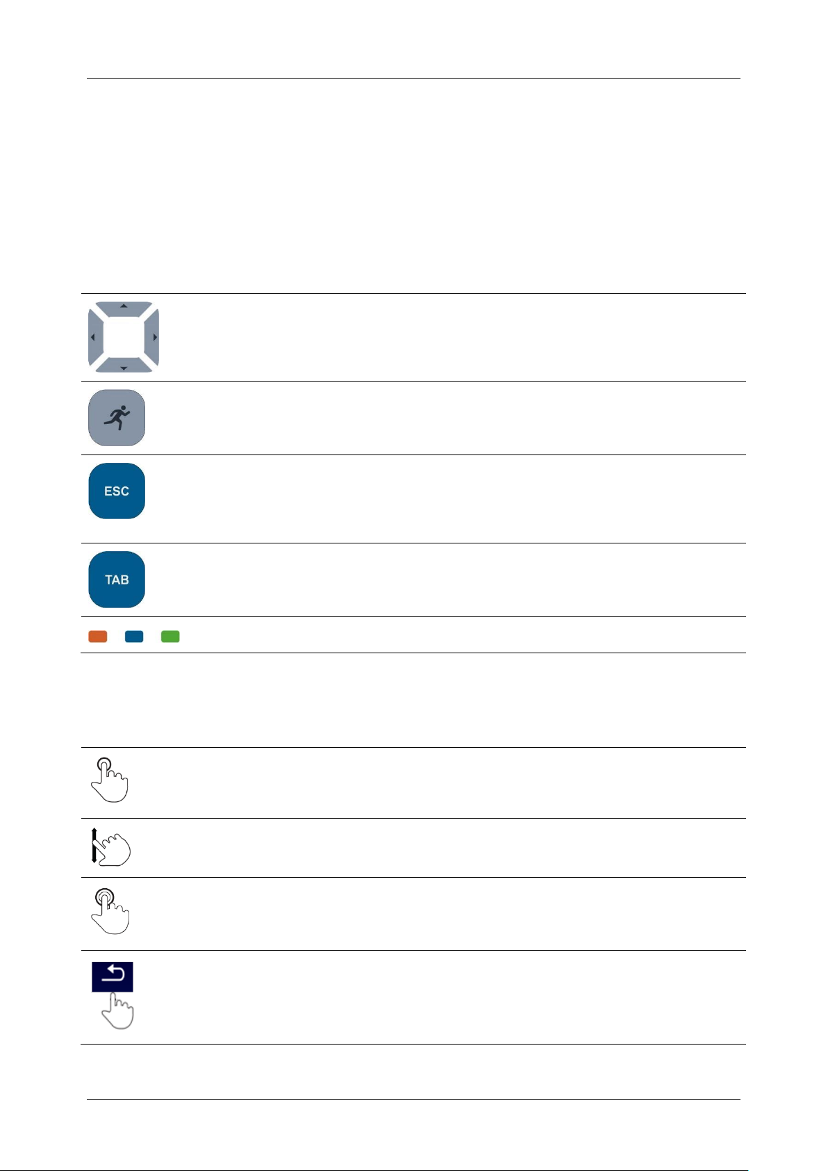
Cursor keys are used to:
- select appropriate option
RUN key is used to:
- confirm selected option
- start and stop measurements
Escape key is used to:
- return to previous menu without changes
- abort measurements
- reset instrument (long press >5 sec)
- switch OFF instrument from standby mode (long press >5 sec)
Option key is used to:
- expand column in control panel
- show detailed view of options
Shortcut keys for immediate access to the Memory Organizer, Auto
Sequences® menu and Single Tests menu.
Tap (briefly touch surface with fingertip) is used to:
- select appropriate option
- confirm selected option
- start and stop measurements
Swipe (press, move, lift) up/ down is used to:
- scroll content in same level
- navigate between views in same level
long
Long press (touch surface with fingertip for at least 1 s) is used to:
- select additional keys (virtual keyboard)
- enter cross selector from single test screens
Tap Escape icon is used to:
- return to previous menu without changes;
- abort / stop measurements
4 Instrument operation
The instrument can be manipulated via a keypad or touch screen.
4.1 General meaning of keys
4.2 General meaning of touch gestures
14
Page 15
MI 3360 OmegaPAT XA Instrument operation
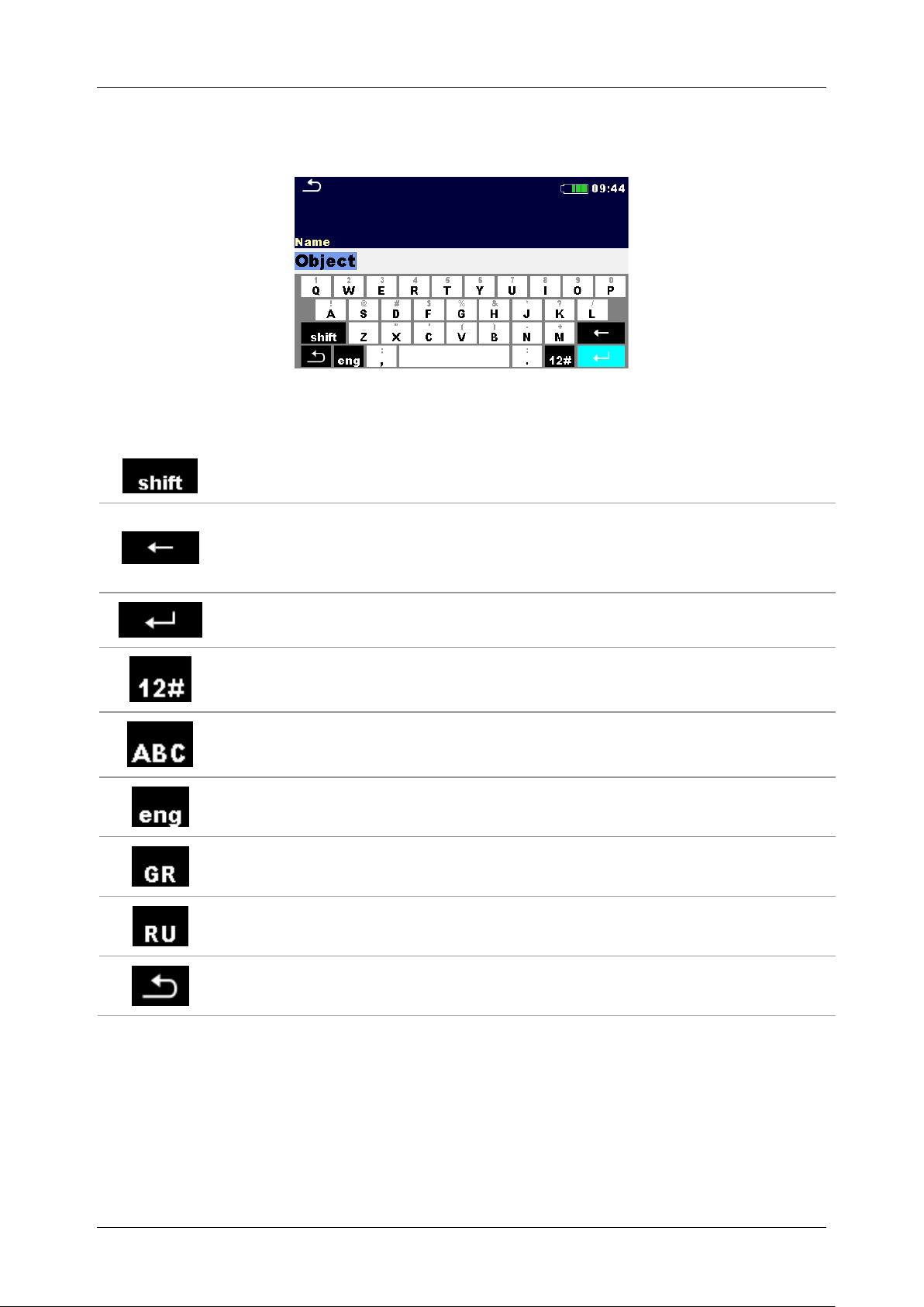
Figure 4.1: Virtual keyboard
Toggle case between lowercase and uppercase.
Active only when alphabetic characters’ keyboard layout selected.
Backspace
Clears last character or all characters if selected.
(If held for 2 s, all characters are selected).
Enter confirms new text.
Activates numeric / symbols layout.
Activates alphabetic characters.
English keyboard layout.
Greek keyboard layout.
Russian keyboard layout.
Returns to the previous menu without changes.
4.3 Virtual keyboard
Options:
4.4 Safety checks
At start up and during operation the instrument performs various safety checks to ensure
safety and to prevent any damage. These safety pre-tests are checking for:
Correct input mains voltage
Presence of input PE connection,
15
Page 16

MI 3360 OmegaPAT XA Instrument operation
Supply voltage warning
Possible causes:
No earth connection.
Instrument is connected to an IT earthing
system. Press YES to continue normally or NO
to continue in a limited mode (measurements are
disabled).
Warning:
The instrument must be earthed properly to work
safely!
Resistance L-N > 30 kΩ
In pre-test a high input resistance was measured.
Possible causes:
Device under test is not connected or switched
on
Input fuse of device under test is blown.
Select YES to proceed with or NO to cancel
measurement.
Resistance L-N < 10 Ω
In pre-test a very low resistance of the device under test
supply input was measured. This can result in a high
current after applying power to the device under test. If
the too high current is only of short duration (caused by
a short inrush current) the test can be performed
otherwise not.
Select YES to proceed with or NO to cancel
measurement
Resistance L-N < 30 Ω
In pre-test a low input resistance of the device under
test was measured. This can result in a high current
after applying power to the device. If the high current is
only of short duration (caused by a short inrush current)
the test can be performed, otherwise not.
Any external voltage against earth on mains test socket
Excessive leakage currents through measuring I/O’s,
Too low resistance between L and N of tested device,
Proper operation of safety relevant internal electronic circuits
If a safety check fails, an appropriate warning message will be displayed and safety
measures will be taken. The warnings and safety measures are described in chapter 4.5
Symbols and messages.
4.5 Symbols and messages
16
Page 17

MI 3360 OmegaPAT XA Instrument operation
Select YES to proceed with or NO to cancel
measurement.
Warning for proper connection in some PRCD
measurements. Connection of PRCD’s plug must be
changed in order to proceed.
Select YES to retry after reconnection with or NO to
cancel measurement.
Warning for improper supply voltage condition. If
pressing OK instrument will continue to work in a limited
mode (measurements are disabled).
In pre-test a too high external voltage was detected
between P and PE terminals. The measurement was
cancelled. Press OK to continue.
In pre-test a too high external voltage was detected
between LN and PE terminals. The measurement was
cancelled. Press OK to continue.
The set Unom differs too much from the measured
mains voltage. Parameter or mains voltage must be
changed.
In pre-test a possible high leakage current was
detected. It is likely that a dangerous leakage current
(higher than 3.5 mA) will flow after applying power to the
device under test.
Select YES to proceed with or NO to cancel
measurement.
The measured leakage (Idiff, Ipe, Itouch) current was
higher than 20 mA. Measurement was aborted. Press
OK to continue.
17
Page 18

MI 3360 OmegaPAT XA Instrument operation
The load current higher than 16 A is detected.
Measurement is aborted. Press OK to continue.
The average load current higher than 10 A over the last
5 min test interval is detected. Measurement is stopped.
Recovery period for cooling is required before
proceeding with tests! Press OK to continue.
The polarity pre-test of the cable / PRCD has failed.
Press OK to continue.
Instrument prohibits the test because 115 V adapter is
connected to the instrument and the instrument is
powered with 230 V.
The instrument is overheated. The measurement can’t
be carried out until the icon disappears. Press OK to
continue.
The device under test should be switched on (to ensure
that the complete circuit is tested).
In case of simultaneously measuring of Riso, Riso-S or
Isub, Isub-S. If the voltage has dropped because of one
measurement the other measurement is also
compromised.
Red dot indicates phase of measurement where higher
leakage was measured. Applicable only if phase
reversal is enabled during the measurement.
Warning!
A high voltage is / will be present on the instrument
output! (Withstanding test voltage, Insulation test
voltage, or mains voltage).
18
Page 19
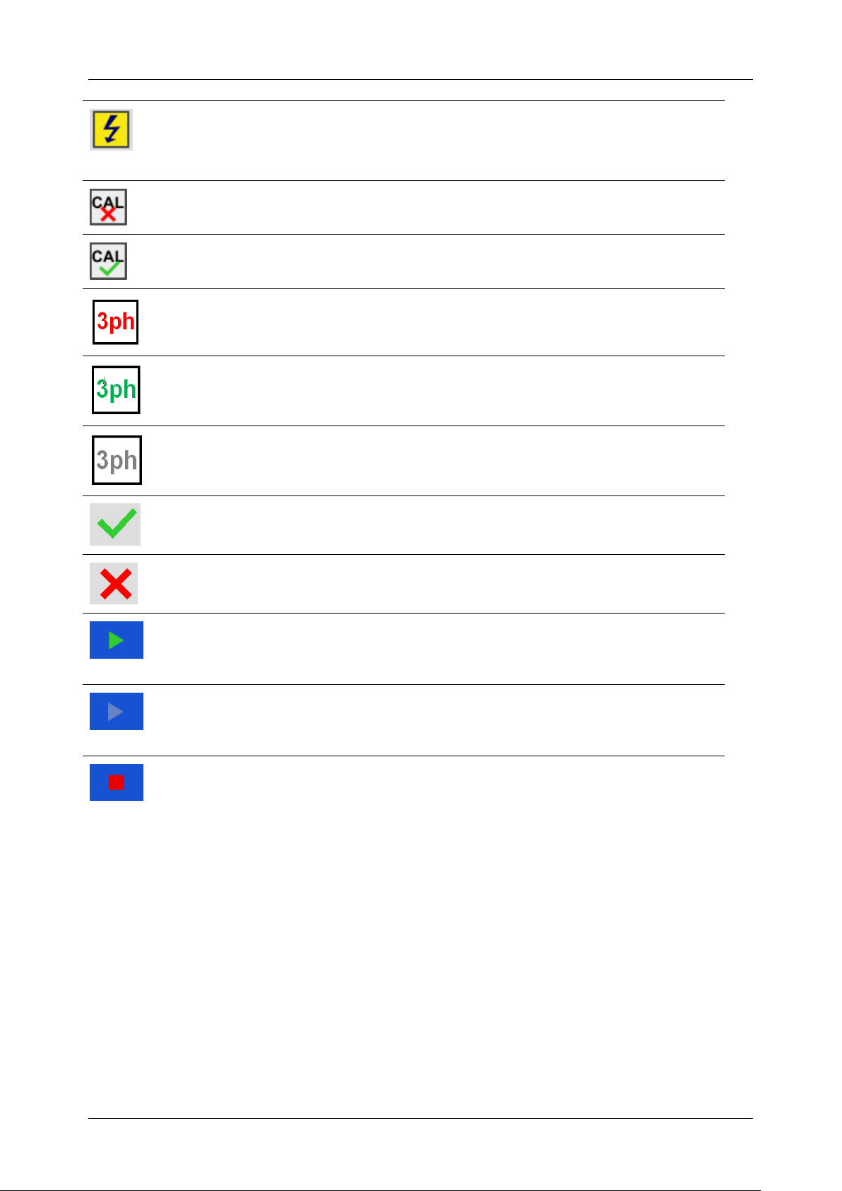
MI 3360 OmegaPAT XA Instrument operation
Warning!
A very high voltage is / will be present on the instrument
output! (Flash test voltage).
Test leads resistance in Continuity / Protective Earth
measurement is not compensated.
Test leads resistance in Continuity / Protective Earth
measurement is compensated.
Measurement can’t be started. 3 phase adapter should
be disconnected from the instrument.
Measurement in combination with appropriate 3 phase
adapter can be carried out.
The measurement can be carried out only in
combination with appropriate 3 phase adapter.
Test passed.
Test failed.
Conditions on the input terminals allow starting the
measurement; consider other displayed warnings and
messages.
Conditions on the input terminals do not allow starting
the measurement, consider displayed warnings and
messages.
Stop the measurement.
19
Page 20

MI 3360 OmegaPAT XA Instrument operation
Figure 4.2: Main menu
Single Tests
Menu with single tests, see chapter 0 Error! Not a valid result for
able..
Auto Sequences®
Menu with customized test sequences, see chapter 7 Auto
Sequences®.
Memory Organizer
Menu for working with and documentation of test data, see chapter 5
Memory Organizer.
General Settings
Menu for setup of the instrument, see chapter 4.7 General settings.
4.6 Instrument main menu
From the instrument Main Menu different main operation menus can be selected.
Options
20
Page 21

MI 3360 OmegaPAT XA Instrument operation
Figure 4.3: Setup menu
Language
Instrument language selection.
Date / Time
Instruments Date and time.
Workspace Manager
Manipulation with project files. Refer to chapter 4.10 Workspace Manager for
more information.
Auto Sequence® groups
Manipulation with lists of Auto Sequences®. Refer to chapter 4.11 Auto
Sequence® groups for more information.
User accounts
User account settings.
Profiles
Selection of available instrument profiles.
Settings
Setting of different system / measuring parameters.
Devices
Setting of external devices.
Initial Settings
Factory settings.
About
Basic instrument data.
4.7 General settings
In the General Settings menu general parameters and settings of the instrument can be viewed
or set.
Options in General Settings menu
21
Page 22

MI 3360 OmegaPAT XA Instrument operation
4.7.1 Language
In this menu the language of the instrument can be set.
Figure 4.4: Select language menu
4.7.2 Date and time
In this menu date and time of the instrument can be set.
Figure 4.5: Setting data and time menu
4.7.3 Profiles
Refer to Chapter 4.9 Instrument profiles for more information.
4.7.4 Workspace Manager
Refer to Chapter 4.10 Workspace Manager for more information.
4.7.5 Auto Sequence® groups
Refer to Chapter 4.11 Auto Sequence® groups for more information.
22
Page 23

MI 3360 OmegaPAT XA Instrument operation
Description
Touch screen
ON – touch screen is active.
OFF – touch screen is deactivated.
Keys & touch sound
ON – sound is active.
OFF – sound is deactivated.
Equipment ID
Increment – offered ID will be incremented +1.
Replicate – offered ID will be the same as last used.
Blank – equipment ID will not be offered.
Equipment name
Replicate – offered name will be the same as last used.
Blank – equipment name will not be offered.
Retest period
Replicate – offered retest period will be the same as last used.
Blank– retest period will not be offered.
Unom
Nominal Line to earth voltage [100 V, 110 V, 120 V, 220 V, 230 V or 240
V] (is used for normalization of leakage current results if testing medical
equipment).
RCD Standard
Selection of appropriate standard for RCD tests.
PRCD Standard
Selection of appropriate standard for PRCD tests.
Ch_1 clamp type
Setting of current clamp type.
Result
In case the measurement consists of multiple measurements taken
successively, the worst or the last result can be displayed at the end.
Worst – the worst result will be displayed at the end of test.
Last – last result will be displayed at the end of test.
Notes:
In general the worst result(s) of the main result is considered.
Sub-result(s) taken at the same time as the worst case of the
main result are displayed.
In the function Leak's & Power the worst case of Idiff and I touch
4.7.6 Settings
Figure 4.6: Settings menu
Setting options:
23
Page 24

MI 3360 OmegaPAT XA Instrument operation
are considered. The Power result measured at the time of worst
Idiff is displayed.
In the function Riso, Riso-S the worst case of Riso and Riso-S
are considered. The Um result measured at the time of worst
Riso is displayed.
For the Power measurement the last result is considered
regardless of the Result setting.
Limit Uc
Conventional touch voltage limit [25 V, 50 V]
Figure 4.7: Initial settings menu
4.7.7 Initial Settings
In this menu internal Bluetooth module can be initialized and the instrument settings,
measurement parameters and limits can be set to initial (factory) values.
Warning!
Following customized settings will be lost when setting the instruments to initial settings:
Measurement limits and parameters
Global parameters, System settings and Devices in General settings menu
Opened Workspace and Auto Sequence® group will be deselected.
User will be signed out.
Note:
Following customized settings will stay:
Profile settings
Data in memory (Data in Memory organizer, Workspaces, Auto Sequence® groups
and Auto Sequences®)
User accounts
4.7.8 About
In this menu instrument data (name, serial number, FW and HW version and date of calibration)
can be viewed.
24
Page 25

MI 3360 OmegaPAT XA Instrument operation
Figure 4.8: Instrument info screen
Note:
Adapter info is also displayed if connected.
4.7.9 User Accounts
The demand to sign in can prevent from unauthorized persons to work with the instrument.
In this menu user accounts can be managed:
Setting if signing in to work with the instrument is required or not.
Adding and deleting new users, setting their user names and passwords.
The user accounts can be managed by the administrator.
Factory set administrator password: ADMIN
It is recommended to change factory set administrator password afer first use. If the custom
password is forgotten the second administrator password can be used. This password always
unlock the Account manager and is delivered with the instrument.
If an user account is set and the user is signed in the user's name will be stored in memory for
each measurement.
Individual users can change their passwords.
4.7.9.1 Signing in
If signing in is demanded the user must enter the password in order to work with the instrument.
Figure 4.9: Sign in menu
25
Page 26

MI 3360 OmegaPAT XA Instrument operation
The user should be selected first. The last used user is
displayed in the first row.
Goes to Password entry menu.
To sign in, the selected user password must be entered and
confirmed.
The user password consist of a up to 4 digit number.
Enters Account manager menu.
The administrator password must be entered and confirmed
first.
Administrator password consists of letters and/or numbers.
Letters are case sensitive.
Signs out the set user.
Options
User signing in
Administrator signing in
4.7.9.2 Changing user password, signing out
Figure 4.10: User profile menu
Options
26
Page 27

MI 3360 OmegaPAT XA Instrument operation
Enters procedure for changing the user’s password.
The actual password must be entered first followed by the
new password.
Enters the Account manager menu.
The Account manager menu is accessed by selecting
Account Manager in Sign in menu or User profile menu. The
administrator password must be entered and confirmed first.
The factory set default administrator password is: ADMIN
Field for setting if signing in is required to work with the
instrument.
Field for setting if signing is required once or at each power
on of the instrument.
Enters procedure for changing the administrator password.
4.7.9.3 Managing accounts
Figure 4.11: Account manager menu
Options
27
Page 28

MI 3360 OmegaPAT XA Instrument operation
The actual password must be entered first followed by the
new password.
Enters menu for editing user accounts.
Opens the window for adding a new user account.
In the Add New window the name and initial password of
the new user account are to be set. ‘Add’ confirms the new
user account.
Changes password of the selected user account.
Deletes all user accounts.
Deletes the selected user account.
Figure 4.12: Edit accounts menu
Options
28
Page 29

MI 3360 OmegaPAT XA Instrument operation
Writing devices
Type
Sets appropriate writing device (Serial printer, Bluetooth printer), RFID
writer).
Port
Sets/views communication port of selected writing device.
Bluetooth device
name
Goes to menu for pairing with selected Bluetooth device.
Bluetooth dongle
Initializes Bluetooth Dongle.
Print labels
Selects label form size. See for details.
Printed date
Selects date printed on label text area, Options: [Test date, Retest
date]. See Appendix C Print labels and write / read RFID / NFC tags for
details.
Auto save
Sets simultaneous saving of finished Auto Sequence when label is
printed or RFID / NFC tag is written. Options: [On print, On write, OFF]
See chapter 7.2.3 Auto Sequence® result screen for details.
Tag format
Sets PAT tag / label format or generic tag /label format. See Appendix
C Print labels and write / read RFID / NFC tags for details.
Reading devices
Type
Sets appropriate reading device (QR or barcode scanner, RFID reader,
android device via aMESM application).
Port
Sets/views communication port of selected reading device.
Bluetooth device
name
Goes to menu for pairing with selected Bluetooth device.
4.8 Devices
In this menu operation with external devices is configured.
Figure 4.13: Devices settings menu
29
Page 30

MI 3360 OmegaPAT XA Instrument operation
Loads the selected profile. The instrument will restart
automatically with new profile loaded.
Enters option for deleting a profile.
Before deleting the selected profile user is asked for
confirmation.
4.9 Instrument profiles
In this menu the instrument profile can be selected from the available ones.
Figure 4.14: Instrument profile menu
The instrument uses different specific system and measuring settings in regard to the scope of
work or country it is used. These specific settings are stored in instrument profiles.
By default each instrument has at least one profile activated. Proper licence keys must be
obtained to add more profiles to the instrument.
If different profiles are available they can be selected in this menu.
Refer to Appendix B Profile Notes for more information about functions specified by profiles.
Options
30
Page 31

MI 3360 OmegaPAT XA Instrument operation
4.10 Workspace Manager
The Workspace Manager is intended to manage with different Workspaces and Exports stored
on the microSD card.
4.10.1 Workspaces and Exports
The works with OmegaPAT XA MI 3360 can be organized with help of Workspaces and
Exports. Exports and Workspaces contain all relevant data (measurements, parameters, limits,
structure objects) of an individual work.
Figure 4.15: Organization of Workspaces and Exports on microSD card
Workspaces are stored on microSD card on directory WORKSPACES, while Exports are stored
on directory EXPORTS. Export files can be read by Metrel applications that run on other
devices. Exports are suitable for making backups of important works or can be used for storage
of works if the removable microSD card is used as a mass storage device. To work on the
instrument an Export should be imported first from the list of Exports and converted to a
Workspace. To be stored as Export data a Workspace should be exported first from the list of
Workspaces and converted to an Export.
4.10.2 Workspace Manager main menu
In Workspace manager Workspaces and Exports are displayed in two separated lists.
Figure 4.16: Workspace manager main menu
31
Page 32

MI 3360 OmegaPAT XA Instrument operation
List of Workspaces.
Displays a list of Exports.
Adds a new Workspace.
Refer to Chapter 4.10.2.3 Adding a new
Workspace for more information.
List of Exports.
Displays a list of Workspaces.
Marks the opened Workspace in Memory Organizer.
Opens the selected Workspace in Memory Organizer.
Refer to chapters 5 Memory Organizer and 4.10.2.4 Opening a Workspace for
more information.
Deletes the selected Workspace.
Refer to chapter 4.10.2.5 Deleting a Workspace / Export for more information.
Adds a new Workspace.
Refer to chapter 4.10.2.3 Adding a new Workspace for more information.
Exports a Workspace to an Export.
Refer to chapter 4.10.2.7 Exporting a Workspace for more information.
Opens options in control panel / expands column.
Options
4.10.2.1 Operations with Workspaces
Only one Workspace can be opened in the instrument at the same time. The Workspace
selected in the Workspace Manager will be opened in the Memory Organizer.
Options
Figure 4.17: Workspaces menu
32
Page 33

MI 3360 OmegaPAT XA Instrument operation
Deletes the selected Export.
Refer to chapter 4.10.2.5 Deleting a Workspace / Export for more information.
Imports a new Workspace from Export.
Refer to chapter 4.10.2.6 Importing a Workspace for more information.
Opens options in control panel / expands column.
New workspaces can be added from the
Workspace manager screen.
Enters option for adding new Workspace.
Keypad for entering name of a new Workspace
is displayed after selecting New.
4.10.2.2 Operations with Exports
Figure 4.18: Workspace manager File menu
Options
4.10.2.3 Adding a new Workspace
33
Page 34

MI 3360 OmegaPAT XA Instrument operation
After confirmation a new Workspace is added in
the list in Main Workspace Manager menu.
Workspace can be selected from a list in
Workspace manager screen.
Opens a Workspace in Workspace manager.
The opened Workspace is marked with a blue
dot. The previously opened Workspace will close
automatically.
Workspace / Export to be deleted should be
selected from the list of Workspaces / Exports.
Opened workspace can’t be deleted.
Enters option for deleting a Workspace / Export.
4.10.2.4 Opening a Workspace
4.10.2.5 Deleting a Workspace / Export
34
Page 35

MI 3360 OmegaPAT XA Instrument operation
Before deleting the selected Workspace / Export
the user is asked for confirmation.
Workspace / Export is removed from the
Workspace / Export list.
Select an Export file to be imported from
Workspace Manager Export list.
Enters option Import.
Before the import of the selected file the user is
asked for confirmation.
The Imported Export file is added to the list of
Workspaces.
Note:
If a Workspace with the same name already exists
the name of the imported Workspace will be
changed (name_001, name_002, name_003…).
4.10.2.6 Importing a Workspace
35
Page 36

MI 3360 OmegaPAT XA Instrument operation
Select a Workspace from Workspace manager
list to be exported to an Export file.
Enters option Export.
Before exporting the selected Workspace, the
user is asked for confirmation.
Workspace is exported to Export file and is
added to the list of Exports.
Note:
If an Export file with the same name already
exists the name of the Export file will be changed
(name_001, name_002, name_003, …).
4.10.2.7 Exporting a Workspace
36
Page 37

MI 3360 OmegaPAT XA Instrument operation
4.11 Auto Sequence® groups
The Auto Sequences® in OmegaPAT XA MI 3360 can be organized by using lists. In a list a
group of similar Auto Sequences® is stored. The Auto Sequence® groups menu is intended to
manage with different lists of Auto Sequences® that are stored on the microSD card.
Figure 4.19: Organization of Auto Sequences® on microSD card
Folders with lists of Auto Sequences® are stored in Root\__MOS__\AT on the microSD card.
4.11.1 Auto Sequence® groups menu
In Auto Sequence® groups menu lists of Auto Sequences® are displayed. Only one list can be
opened in the instrument at the same time. The list selected in the Auto Sequence® groups
menu will be opened in the Auto Sequences® main menu.
Figure 4.20: Auto Sequence® groups menu
37
Page 38

MI 3360 OmegaPAT XA Instrument operation
Opens the selected list of Auto Sequences®. Previously selected list of Auto
Sequences® will be closed automatically.
Refer to chapter 4.11.1.2 Selecting a list of Auto Sequences® for more
information.
Deletes the selected list of Auto Sequences.
Refer to chapter 4.11.1.3 Deleting a list of Auto Sequences® for more
information.
Opens options in control panel / expands column.
A list of Auto Sequences® can be selected
from the Auto Sequence® groups menu.
Enters option for selecting a list.
Selected list of Auto Sequences® is marked
with a blue dot.
Note:
Previously selected list of Auto Sequences®
is closed automatically.
4.11.1.1 Operations in Auto Sequence® groups menu
Options
4.11.1.2 Selecting a list of Auto Sequences®
38
Page 39

MI 3360 OmegaPAT XA Instrument operation
A list of Auto Sequences® to be deleted can
be selected from the Auto Sequence® groups
menu.
Enters option for deleting a list.
+ Before deleting the selected list of Auto
Sequences® the user is asked for
confirmation.
A list of Auto Sequences® is removed.
4.11.1.3 Deleting a list of Auto Sequences®
39
Page 40

MI 3360 OmegaPAT XA Memory Organizer
passed finished single test with test results
failed finished single test with test results
finished single test with test results and no status
empty single test without test results
or
at least one single test in the Auto
sequence passed and no single test
failed
or
at least one single test in the Auto
sequence failed
5 Memory Organizer
Memory Organizer is a tool for storing and working with test data.
5.1 Memory Organizer menu
The data is organized in a tree structure with Structure objects and Measurements. OmegaPAT
XA has a multi-level structure. The hierarchy of Structure objects in the tree is shown on Figure
5.1. In Appendix A Structure objects in
OmegaPAT XA is a list of available structure objects.
Figure 5.1: Tree structure and its hierarchy
5.1.1 Measurement statuses
Each measurement has:
a status (Pass or Fail or no status)
a name
results
limits and parameters
A measurement can be a Single test or an Auto Sequence.
For more information, refer to chapters 6 Single tests and 7 Auto Sequences®.
Statuses of Single tests
Overall statuses of Auto Sequence
40
Page 41

MI 3360 OmegaPAT XA Memory Organizer
or
at least one single test in the Auto
sequence was carried out and there
were no other passed or failed single
tests
or
empty Auto sequence with empty single
tests
There are no measurement result(s)
under selected structure object.
Measurements should be made.
Figure 5.3: Example of status - No
measurement result(s)
5.1.2 Structure Objects
Each Structure object has:
an icon
a name
parameters
Optionally they can have:
an indication of the status of the measurements under the Structure object
a comment or a file attached
Structure objects supported are described in Appendix A Structure objects in
OmegaPAT XA.
Figure 5.2: Structure object in tree menu
5.1.2.1 Measurement status indication under the Structure object
Overall status of measurements under each structure element / sub-element can be seen
without spreading tree menu. This feature is useful for quick evaluation of test status and as
guidance for measurements.
Options
41
Page 42

MI 3360 OmegaPAT XA Memory Organizer
One or more measurement result(s)
under selected structure object has
failed. Not all measurements under
selected structure object have been
made yet.
Figure 5.4: Example of status -
Measurements not completed with fail
result(s)
All measurements under selected
structure object are completed but one
or more measurement result(s) has
failed.
Figure 5.5: Status - Measurements
completed with fail result(s)
Press the active Workspace in Memory Organizer
Menu.
Select List of Workspaces in Control panel.
Note:
There is no status indication if all measurement results under each structure element /
sub-element have passed or if there is an empty structure element / sub-element
(without measurements).
5.1.3 Selecting an active Workspace in Memory Organizer
Memory Organizer and Workspace Manager are interconnected so an active Workspace can be
selected also in the Memory Organizer menu.
Procedure
42
Page 43

MI 3360 OmegaPAT XA Memory Organizer
Choose desired Workspace from a list of
Workspaces.
Use Select button to confirm selection.
New Workspace is selected and displayed on the
screen.
Press the active Workspace in Memory
Organizer Menu.
Select Add New Structure Element in Control
panel.
5.1.4 Adding Nodes in Memory Organizer
Structural Elements (Nodes) are used to ease organization of data in the Memory Organizer.
One Node is a must; others are optional and can be created or deleted freely.
Procedure
43
Page 44

MI 3360 OmegaPAT XA Memory Organizer
Change name of the Node if necessary and
press Add to confirm.
New Structure Element (Node) will be added.
Views results of measurement.
The instrument goes to the measurement memory screen. Refer to chapters
6.1.1.5 Single test memory screen and 7.2.4 Auto Sequence® memory screen
Auto Sequence® memory screen for more information.
5.1.5 Operations in Tree Menu
In the Memory organizer different actions can be taken with help of the control panel at the right
side of the display. Possible actions depend on the selected element in the organizer.
5.1.5.1 Operations on measurements (finished or empty measurements)
The measurement must be selected first. Operation options can be selected from the menu on
the right side of the screen. Menu options are adopted to measurement status, empty, finished,
finished and saved, as presented on Figure 5.6.
Figure 5.6: A measurement is selected in the tree menu
Options
44
Page 45

MI 3360 OmegaPAT XA Memory Organizer
Starts a new measurement.
The instrument goes to the measurement start screen. Refer to chapters
6.1.1.1 Single test start screen and 7.2.1 Auto Sequence® view menu for more
information.
Saves a measurement.
Saving of measurement on a position after the selected (empty or finished)
measurement.
Clones the measurement.
The selected measurement can be copied as an empty measurement under
the same Structure object. Refer to Chapter 5.1.5.7 Clone a measurement for
more information.
Copies & Paste a measurement.
The selected measurement can be copied and pasted as an empty
measurement to any location in structure tree. Multiple “Paste” is allowed.
Refer to Chapter 5.1.5.9 Copy & Paste a measurement for more information.
Adds a new measurement.
The instrument goes to the Menu for adding measurements. Refer to Chapter
5.1.5.5 Add a new measurement for more information.
Views and edit comments.
The instrument displays comment attached to the selected measurement or
opens keypad for entering a new comment.
Deletes a measurement.
Selected Measurement can be deleted. User is asked for confirmation before
the deleting. Refer to Chapter 5.1.5.11 Delete a measurement for more
information.
Starts a new measurement.
First type of measurement (single test or Auto sequence®) should be selected.
After proper type is selected the instrument goes to single test or Auto
5.1.5.2 Operations on Structure objects
The structure object must be selected first.
Figure 5.7: A structure object is selected in the tree menu
Options
45
Page 46

MI 3360 OmegaPAT XA Memory Organizer
Sequence® selection screen. Refer to Chapters 6.1 Selection modes and 7.1
Selection of Auto Sequences® for more information.
Saves a measurement.
Saving of measurement under the selected Structure object.
View / edit parameters and attachments.
Parameters and attachments of the Structure object can be viewed or edited.
Refer to Chapter 5.1.5.3 View / Edit parameters and attachments of a Structure
object for more information.
Adds a new measurement.
The instrument goes to the Menu for adding measurement into structure. Refer
to Chapter 5.1.5.5 Add a new measurement for more information.
Adds a new Structure object.
A new Structure object can be added. Refer to Chapter 5.1.5.4 Add a new
Structure Object for more information.
Attachments.
Name and link of attachment is displayed.
Clones a Structure object.
Selected Structure object can be copied to same level in structure tree (clone).
Refer to Chapter 5.1.5.6 Clone a Structure object for more information.
Copies & Paste a Structure object.
Selected Structure object can be copied and pasted to any allowed location in
structure tree. Multiple “Paste” is allowed. Refer to Chapter 5.1.5.8 Copy & Paste
a Structure object for more information.
Views and edit comments.
The instrument displays comment attached to the selected Structure object or
opens keypad for entering a new comment.
Deletes a Structure object.
Selected Structure object and sub-elements can be deleted. User is asked for
confirmation before the deleting. Refer to Chapter 5.1.5.10 Delete a Structure
object for more information.
Renames a Structure object.
Selected Structure object can be renamed via keypad. Refer to Chapter 5.1.5.12
Rename a Structure object for more information.
46
Page 47

MI 3360 OmegaPAT XA Memory Organizer
Parameters
Figure 5.8: Example of View / Edit parameters menu
Select structure object to be edited.
Select Parameters in Control panel.
Example of Parameters menu.
In menu for editing parameters the parameter’s
value can be selected from a dropdown list or
entered via keypad. Refer to chapter 4 Instrument
operation for more information about keypad
operation.
5.1.5.3 View / Edit parameters and attachments of a Structure object
The parameters and their content are displayed in this menu. To edit the selected parameter tap
on it or press RUN key to enter menu for editing parameters.
Procedure and options
47
Page 48

MI 3360 OmegaPAT XA Memory Organizer
a
Select Attachments in Control panel.
a
Attachments
The name of attachment can be seen. Operation
with attachments is not supported in the
instrument.
b
Select Comments in Control panel.
b
View or edit comments
Complete comment (if exists) attached to the
structure object can be seen on this screen.
Press RUN key or tap on screen to open keypad
for entering a new comment.
48
Page 49

MI 3360 OmegaPAT XA Memory Organizer
Add Structure
Figure 5.9: Add a new Structure Object menu
Default initial structure.
Select Add Structure in Control panel.
Add a new structure object menu.
a
The type of structure object to be added can be
selected first from dropdown menu.
Only structure objects that can be used in the
same level or next sub-level are offered.
b
The name of structure object can be edited.
5.1.5.4 Add a new Structure Object
This menu is intended to add new structure objects in the tree menu. A new structure object can
be selected and then added in the tree menu.
Procedure and options
49
Page 50

MI 3360 OmegaPAT XA Memory Organizer
c
Parameters of the Structure object can be edited.
Adds the selected structure object in the tree
menu.
Returns to the tree menu without changes.
New object added.
50
Page 51

MI 3360 OmegaPAT XA Memory Organizer
Add Measurement
Figure 5.10: Add a new measurement menu
Select level in structure where measurement will
be added.
Select Add measurement in Control panel.
Add new measurement menu.
a
Type of test can be selected from this field.
Options: (Single Tests, Auto Sequences)
Tap on field or press the RUN key to modify.
b
Last added measurement is offered by default.
To select another measurement tap on filed or
press the RUN to open menu for selecting
measurements. Refer to Chapters 6.1 Selection
modes and 7.1 Selection of Auto Sequences for
more information.
5.1.5.5 Add a new measurement
In this menu new empty measurements can be set and then added in the structure tree. The
type of measurement, measurement function and its parameters are first selected and then
added under the selected Structure object.
Procedure and options
51
Page 52

MI 3360 OmegaPAT XA Memory Organizer
c
Select parameter and modify it as described
earlier.
Refer to Chapter 6.1.1.2 Setting parameters and
limits of single tests for more information.
Adds the measurement under the selected
Structure object in the tree menu.
Returns to the structure tree menu without
changes.
New empty measurement is added under the
selected Structure object.
52
Page 53

MI 3360 OmegaPAT XA Memory Organizer
Clone
Figure 5.11: Clone Structure Object menu
Select the structure object to be cloned.
Clone
Select Clone option from control panel.
The Clone Structure object menu is displayed.
Sub-elements of the selected structure object
can be marked or un-marked for cloning.
Refer to Chapter 5.1.5.8 Copy & Paste a
Structure object for more information.
a
Selected structure object is copied (cloned) to
same level in the structure tree.
b
Cloning is cancelled. No changes in the
Structure tree.
The new structure object is displayed.
5.1.5.6 Clone a Structure object
In this menu selected structure object can be copied (cloned) to same level in the structure tree.
Cloned structure object have same name as original.
Procedure and options
53
Page 54

MI 3360 OmegaPAT XA Memory Organizer
Select the measurement to be cloned.
Clone
Select Clone option from control panel.
The new empty measurement is displayed.
Select the structure object to be copied.
Copy
Select Copy option from control panel.
Select location where structure element
should be copied.
5.1.5.7 Clone a measurement
By using this function a selected empty or finished measurement can be copied (cloned) as an
empty measurement to the same level in the structure tree.
Procedure and options
5.1.5.8 Copy & Paste a Structure object
In this menu selected Structure object can be copied and pasted to any allowed location in the
structure tree.
Procedure and options
54
Page 55

MI 3360 OmegaPAT XA Memory Organizer
Paste
Select Paste option from control panel.
The Paste structure object menu is
displayed. Before copying it can be set which
sub-elements of the selected structure object
will be copied too. For more details see
options below.
a
The selected structure object and elements
are copied (pasted) to selected position in
the tree structure.
b
Returns to the tree menu without changes.
The new structure object is displayed.
Note:
The Paste command can be executed one or
more times.
Parameters of selected structure object will
be copied too.
Attachments of selected structure object will
be copied too.
Structure objects in sub-levels of selected
structure object will be copied too.
Measurements in selected structure object
and sub-levels will be copied too.
Options
55
Page 56

MI 3360 OmegaPAT XA Memory Organizer
Select the measurement to be copied.
Copy
Select Copy option from control panel.
Select location where measurement should be
pasted.
Paste
Select Paste option from control panel.
The new (empty) measurement is displayed in
selected Structure object.
Note:
The Paste command can be executed one or
more times.
5.1.5.9 Copy & Paste a measurement
In this menu selected measurement can be copied to any allowed location in the structure tree.
Procedure
56
Page 57

MI 3360 OmegaPAT XA Memory Organizer
Select the structure object to be deleted.
Delete
Select Delete option from control panel.
A confirmation window will appear.
a
Selected structure object and its sub-elements
are deleted.
b
Returns to the tree menu without changes.
Select a measurement to be deleted.
5.1.5.10 Delete a Structure object
In this menu selected Structure object can be deleted.
Procedure
5.1.5.11 Delete a measurement
In this menu selected measurement can be deleted.
Procedure
57
Page 58

MI 3360 OmegaPAT XA Memory Organizer
Delete
Select Delete option from control panel.
A confirmation window will appear.
a
Selected measurement is deleted.
b
Returns to the tree menu without changes.
Select the structure object to be renamed.
Rename
Select Rename option from control panel.
Virtual keypad will appear on screen. Enter new
text and confirm.
5.1.5.12 Rename a Structure object
In this menu selected Structure object can be renamed.
Procedure
58
Page 59

MI 3360 OmegaPAT XA Memory Organizer
Select the measurement to be recalled.
Recall results
Select Recall results in control panel.
Measurement is recalled.
Parameters and limits can be viewed but
cannot be edited.
Retest
Select Retest in control panel.
Measurement retest starting screen is
displayed.
a
Parameters and limits can be viewed and
edited.
Start Test
Select Run in control panel to retest the
measurement.
5.1.5.13 Recall and Retest selected measurement
Procedure
59
Page 60

MI 3360 OmegaPAT XA Memory Organizer
Results / sub-results after re-run of recalled
measurement.
Save results
Select Save results in control panel.
Retested measurement is saved under same
structure item as original one.
Refreshed memory structure with the new
performed measurement is displayed.
Search function is available from the active
workspace directory line.
Search
Select Search in control panel to open Search
setup menu.
The parameters that can be searched for are
displayed in the Search setup menu.
Name and status are referred to all structure
objects. If searching by status, instrument will
display all structure objects that include one or
more measurements with searched status.
Equipment ID, Test date, Retest date refer only to
the following structure objects: Appliance,
Appliance FD, Medical equipment, Medical
equipment FD, Welding equipment and Welding
equipment FD.
5.1.6 Searching in Memory Organizer
In Memory organizer it is possible to search for different structure objects and parameters.
Procedure
60
Page 61

MI 3360 OmegaPAT XA Memory Organizer
a
The search can be narrowed by entering a text in
the Name and Equipment ID fields.
Strings can be entered using the on-screen
keyboard.
Note:
The Search function on Equipment ID is case
sensitive.
b
The search can be narrowed on base of statuses.
c
The search can be narrowed on base of test dates
/ retest dates (from / to).
d
Clear filters
Clears all filters. Sets filters to default value.
Search
Searches through the Memory Organizer for
objects according to the set filters.
The results are shown in the Search results screen
presented on Figure 5.12 and Figure 5.13.
Figure 5.12: Search results screen – Page view
61
Page 62

MI 3360 OmegaPAT XA Memory Organizer
Next page.
Previous page.
Goes to location in Memory Organizer.
View / edit parameters and attachments.
Parameters and attachments of the Structure object can be viewed or edited.
Refer to Chapter 5.1.5.3 View / Edit parameters and attachments of a
Structure object for more information.
Attachments.
Name and link of attachment is displayed.
Views comment.
The instrument displays comment attached to the selected Structure object.
Renames the selected Structure object.
Refer to Chapter 5.1.5.12 Rename a Structure object for more information.
Options
Note:
Search result page consist of up to 50 results.
Options
Figure 5.13: Search results screen with structure object selected
62
Page 63

MI 3360 OmegaPAT XA Single tests
Area Group
With help of area groups it is possible to limit
the offered single tests. The instrument has
three area groups:
Portable appliances
Medical equipment
Welding equipment
Group All combine all single tests.
Last used
Up to last 9 different executed single tests
within selected Area group are displayed.
Groups
The single tests are divided into groups of
similar tests within selected Area group.
6 Single tests
Single tests can be selected in the Main single test menu or in Memory Organizer’s main and
submenus.
6.1 Selection modes
In Single tests main menu Area group and two different modes for selecting single tests are
available.
Options
63
Page 64

MI 3360 OmegaPAT XA Single tests
For the selected group a submenu with all
single tests that belongs to the selected group
and Area group is displayed.
Name of function
Main result
Subresult
Parameters (white) and
limits (red)
Statuses, info, warnings
Options
6.1.1 Single test screens
In the Single test screens measuring results, sub-results, limits and parameters of the
measurement are displayed. In addition on-line statuses, warnings and other information are
displayed.
Figure 6.1: Single test screen organisation
64
Page 65

MI 3360 OmegaPAT XA Single tests
Starts the measurement.
Opens help screens. Refer to chapter 6.1.3 Help
screens for more information.
on
Opens menu for changing parameters and limits.
Refer to chapter 6.1.1.2 Setting parameters and
limits of single tests for more information.
6.1.1.1 Single test start screen
Single test start screen can be opened from Memory organizer or from Single test main menu.
Figure 6.2: Single test start screen
Options
65
Page 66

MI 3360 OmegaPAT XA Single tests
Selects parameter (white) or limit (red).
Selects value of parameter or limit.
In case of many (multiple pages of) parameters or limits:
- The scroll bar on the right side of screen can be
used
- With right / left keys it can be jumped page up /
page down
Enters custom value of parameter or limit.
Custom values can be entered by using the on-screen
keyboard.
6.1.1.2 Setting parameters and limits of single tests
Figure 6.3: Screens in menu for setting Single test parameters and limits
Options
66
Page 67

MI 3360 OmegaPAT XA Single tests
Stops the single test measurement.
Proceeds to the next step of the measurement (if measurement consists of more
steps).
Aborts measurement.
6.1.1.3 Single test screen during test
Options (during test)
Figure 6.4: Single test screen (during measurement)
67
Page 68

MI 3360 OmegaPAT XA Single tests
Starts a new measurement.
Saves the result.
A new measurement was selected and started from a Structure object in the
structure tree:
- The measurement will be saved under the selected Structure object.
A new measurement was started from the Single test main menu:
- Saving under the last selected Structure object will be offered by default.
The user can select another Structure object or create a new Structure
object. By pressing the key in Memory organizer menu the
measurement is saved under selected location.
An empty measurement was selected from structure tree and started:
- The result(s) will be added to the measurement. The measurement will
change its status from ‘empty’ to ‘finished’.
An already carried out measurement was selected from structure tree, viewed
and then restarted:
- A new measurement will be saved under the selected Structure object.
Adds comment to the measurement. The instrument opens keypad for entering
a comment.
Opens help screens. Refer to chapter 6.1.3 Help
screens for more information.
6.1.1.4 Single test result screen
Figure 6.5: Single test result screen
Options (after measurement is finished)
68
Page 69

MI 3360 OmegaPAT XA Single tests
on
Opens screen for changing parameters and limits.
Refer to chapter 6.1.1.2 Setting parameters and
limits of single tests for more information.
long on
Enters cross selector. Refer to chapter 6.1
Selection modes for more information.
on
Opens menu for viewing parameters and limits.
Refer to chapter 6.1.1.2 Setting parameters and
limits of single tests for more information.
Retest
Enters screen with “empty” measurement.
6.1.1.5 Single test memory screen
Options
Figure 6.6: Single test memory screen
69
Page 70

MI 3360 OmegaPAT XA Single tests
Starts the inspection.
6.1.2 Single test (inspection) screens
Visual and Functional inspections can be treated as a special class of tests. Items to be visually
or functionally checked are displayed. In addition on-line statuses and other information are
displayed.
Figure 6.7: Inspection screen organisation
6.1.2.1 Single test (inspection) start screen
Figure 6.8: Inspection start screen
Options (inspection screen was opened in Memory organizer or from Single test main menu)
70
Page 71

MI 3360 OmegaPAT XA Single tests
Opens help screens. Refer to chapter 6.1.3 Help screens for more
information.
Selects item.
Applies a pass to the selected item or group of items.
Applies a fail to the selected item or group of items.
Clears status in selected item or group of items.
Applies a status that item or group of items was
checked.
on
A status can be applied.
Multiple taps toggles between statuses.
Toggle between statuses.
Power is applied to the mains test socket to power up
the tested equipment during a functional inspection.
The instrument displays and starts the Power
measurement, refer to Chapter 6.2.9 Power.
Stops Power measurement.
Stops the inspection.
6.1.2.2 Single test (Inspection) screen during test
Figure 6.9: Inspection screen (during inspection)
Options (during test)
71
Page 72

MI 3360 OmegaPAT XA Single tests
Stops the inspection.
Goes to the result screen.
Starts a new inspection.
Saves the result.
A new inspection was selected and started from a Structure object in the
structure tree:
- The inspection will be saved under the selected Structure object.
Rules for automatic applying of statuses:
The parent item(s) can automatically get a status on base of statuses in child items.
- the fail status has highest priority. A fail status for any item will result in a fail status in all
parent items and an overall fail result.
- if there is no fail status in child items the parent item will get a status only if all child items
have a status.
- Pass status has priority over checked status.
The child item(s) will automatically get a status on base of status in the parent item
- All child items will get the same status as applied to the parent item.
Note
Inspections and even inspection items inside one inspection can have can have different
status types. For example some basic inspections don’t have the ‘checked’ status.
Only inspections with overall statuses can be saved.
6.1.2.3 Single test (Inspection) result screen
Figure 6.10: Inspection result screen
Options (after inspection is finished)
72
Page 73

MI 3360 OmegaPAT XA Single tests
A new inspection was started from the Single test main menu:
- Saving under the last selected Structure object will be offered by
default. The user can select another Structure object or create a
new Structure object. By pressing the key in Memory
organizer menu the inspection is saved under selected location.
An empty inspection was selected in structure tree and started:
- The result(s) will be added to the inspection. The inspection will
change its status from ‘empty’ to ‘finished’.
An already carried out inspection was selected in structure tree, viewed
and then restarted:
- A new measurement will be saved under the selected Structure
object.
Adds comment to the measurement. The instrument opens keypad for
entering a comment.
Opens help screens. Refer to chapter 6.1.3 Help screens for more
information.
Retest
Starts inspection with cleared statuses.
Enters view mode.
6.1.2.4 Single test (inspection) memory screen
Figure 6.11: Inspection memory screen
Options
73
Page 74

MI 3360 OmegaPAT XA Single tests
Opens help screen.
on
Goes to previous / next help screen.
6.1.3 Help screens
Help screens contain diagrams for proper connection of the instrument.
Figure 6.12: Examples of help screens
Options:
74
Page 75

MI 3360 OmegaPAT XA Single tests
Figure 6.13: Visual inspection menu
Figure 6.14: Visual inspection test circuit
Select the appropriate Visual function.
Start the inspection.
Perform the visual inspection of the appliance / equipment.
Apply appropriate ticker(s) to items of inspection.
End inspection.
Save results (optional).
6.2 Single test measurements
6.2.1 Visual inspection
Test circuit
Visual inspection procedure
Figure 6.15: Examples of Visual inspection results
75
Page 76

MI 3360 OmegaPAT XA Single tests
Figure 6.16: Continuity test // Protective earth resistance menu
Output (Continuity)
Output: [P/S – PE, MS_PE – IEC_PE]
Output (Protective earth resistance)
Output: [P/S – PE]
Test current
I out: [0.2 A, 10 A, 25 A]
Duration
Duration: [Off, 2 s … 180 s]
Limit (R) (Continuity)
H Limit(R): [Off, 0.01 Ω … 9 Ω, Custom]
Limit (R) (Protective earth resistance)
Limit(R): [Off, 0.1 Ω … 0.5 Ω]
Figure 6.17: Continuity MS PE – IEC PE
6.2.2 Continuity // Protective earth resistance
Test results / sub-results
R ................ Resistance
Test parameters
Test limits
Test circuits
76
Page 77

MI 3360 OmegaPAT XA Single tests
Figure 6.18: Continuity P/S – PE
Figure 6.19: Protective Earth Resistance
Select the Continuity // Protective Earth Resistance function.
Set test parameters / limits.
Connect device under test to the instrument (see test circuits above).
Start measurement.
Measurement can be stopped manually or by timer.
Save results (optional).
Continuity // Protective earth resistance measurement procedure
77
Page 78

MI 3360 OmegaPAT XA Single tests
Select the Continuity // Protective Earth Resistance function.
Set parameters (Output, Test current).
Connect test lead to the instrument between P/S terminal and PE terminal on test socket or
connect IEC test cable between IEC connector and test socket, depending on settings, see
Figure 6.21.
Touch the key to compensate test lead / IEC test cable resistance.
Symbol is displayed if the compensation was carried out successfully.
Figure 6.20: Example of Continuity and Protective Earth Resistance measurement results
6.2.2.1 Compensation of test lead / IEC test cable resistance
This chapter describes how to compensate the test leads resistance in Continuity (Output =
P/S – PE) and Protective Earth Resistance (Output = P/S – PE) functions, and how to
compensate IEC test cable resistance in Continuity (Output = MS_PE – IEC_PE) and PE
conductor (PRCD) functions. Compensation can be carried out to eliminate the influence of
test lead / IEC test cable resistance and the internal resistances of the instrument and adapters
on the measured resistance.
Connection for compensating the resistance of test lead / IEC test cable
Figure 6.21: Shorted test lead / IEC test cable
Compensation of test lead / IEC test cable resistance procedure
78
Page 79

MI 3360 OmegaPAT XA Single tests
Figure 6.23: Flash test menu
Output test voltage
U test: [1500 V, 3000 V)
Duration
Duration: [Off, 2 s … 180 s]
Limit (I)
Limit(I): [0.50 mA … 2.25 mA ]
Figure 6.22: Result with old and new calibration values
Note:
The calibration value is correct only for the output (P/S terminal – PE terminal on test socket)
at which the calibration was carried out.
6.2.3 Flash test
Test results / sub-results
I ................. measured a.c. test current
Test parameters
Test limits
79
Page 80

MI 3360 OmegaPAT XA Single tests
Figure 6.24: Flash test 1500 V
Figure 6.25: Flash test 3000 V
Select the Flash function.
Set test parameters / limits.
Connect device under test to the instrument (see test circuits above).
Start measurement.
Measurement can be stopped manually or by timer.
Save results (optional).
Figure 6.26: Examples of Flash measurement results
Test circuits
Flash measurement procedure
80
Page 81

MI 3360 OmegaPAT XA Single tests
Type of test
Type [Riso, Riso-S, (Riso, Riso-S)]
Nominal test voltage
Uiso [250 V, 500 V]
Duration
Duration [Off, 2 s … 180 s]
Limit (Riso)
L Limit(Riso) [Off, 0.01 MΩ … 10.0 MΩ ]
Limit (Riso-S)
L Limit(Riso-S) [Off, 0.10 MΩ … 10.0 MΩ ]
Figure 6.28: Insulation resistance Riso (socket)
Figure 6.29: Insulation resistance Riso (LN – PE)
6.2.4 Insulation resistance (Riso, Riso-S)
Figure 6.27: Insulation resistance test menus
Test results / sub-results
Riso ........... Insulation resistance
Riso-S ....... Insulation resistance-S
Um............. Test voltage
Test parameters
Test limits
Test circuits
81
Page 82

MI 3360 OmegaPAT XA Single tests
Figure 6.30: Insulation resistance measurement with probe Riso-S (socket – P/S)
Select the R iso function.
Set test parameters / limits.
Connect device under test to the instrument (see test circuits above).
Start measurement.
Measurement can be stopped manually or by timer.
Save results (optional).
Figure 6.31: Examples of Insulation resistance measurement results
Insulation resistance measurement procedure
Note:
The current through the P/S probe is also considered in the Riso result.
6.2.5 Sub-leakage (Isub, Isub-S)
Figure 6.32: Sub Leakage test menus
Test results / sub-results
Isub ........... Sub-leakage current
Isub-S ........ Sub-leakage current-S
82
Page 83

MI 3360 OmegaPAT XA Single tests
Type of test
Type [Isub, Isub-S, (Isub, Isub-S)]
Output voltage
Output [230 V]ac
Duration
Duration [Off, 2 s … 180 s]
Limit (Isub)
H Limit(Isub) [Off, 0.25 mA … 15.0 mA, Custom]
Limit (Isub-S)
H Limit(Isub-S) [Off, 0.25 mA … 15.0 mA]
Figure 6.33: Sub-leakage Isub (socket)
Figure 6.34: Sub-leakage Isub (LN – PE)
Figure 6.35: Sub-leakage measurement with probe Isub-S (socket – P/S)
Test parameters
Test limits
Test circuits
83
Page 84

MI 3360 OmegaPAT XA Single tests
Select the Sub-leakage function.
Set test parameters / limits.
Connect device under test to the instrument (see test circuits above).
Start measurement.
Measurement can be stopped manually or by timer.
Save results (optional).
Figure 6.36: Examples of Sub-leakage measurement results
Sub-leakage measurement procedure
Note:
When P/S probe is connected during the Sub-leakage measurement, then the current
through it is also considered.
6.2.6 Differential Leakage
Figure 6.37: Differential Leakage test menu
Test results / sub-results
Idiff ............ Differential Leakage current
P ................ Power
84
Page 85

MI 3360 OmegaPAT XA Single tests
Duration
Duration [Off, 2 s … 180 s]
Change status
Change [YES, NO]
YES: The instrument measures leakage current in two sequential
steps with delay* in between. The phase voltage is firstly
applied to the right live output of the mains test socket and
secondly to the left live output of the mains test socket.
NO: The phase voltage is applied only to the right live output of the
mains test socket.
*Delay time
Delay [0.2 s … 5 s]
Limit (Idiff)
H limit [Off, 0.25 mA … 15.0 mA, Custom]
Select the Differential Leakage function.
Set test parameters / limits.
Connect device under test to the instrument (see test circuits above).
Start measurement.
Measurement can be stopped manually or by timer.
Save results (optional).
Test parameters
Test limits
Test circuit
Figure 6.38: Differential leakage
Differential Leakage measurement procedure
Figure 6.39: Examples of Differential Leakage measurement results
85
Page 86

MI 3360 OmegaPAT XA Single tests
Duration
Duration [Off, 2 s … 180 s]
Change status
Change [YES, NO]
YES: The instrument measures leakage current in two sequential steps
with delay* in between. The phase voltage is firstly applied to the
right live output of the mains test socket and secondly to the left
live output of the mains test socket.
NO: The phase voltage is applied only to the right live output of the
mains test socket.
*Delay time
Delay [0.2 s … 5 s]
Limit (Ipe)
H Limit(Ipe) [Off, 0.25 mA … 15.0 mA, Custom]
Select the Ipe Leakage function.
Set test parameters / limits.
Connect device under test to the instrument (see test circuit above).
Start measurement.
Measurement can be stopped manually or by timer.
6.2.7 Ipe Leakage
Figure 6.40: Ipe Leakage test menu
Test results / sub-results
Ipe ............. PE current
P ................ Power
Test parameters
Test limits
Test circuit
Figure 6.41: Ipe leakage
Ipe Leakage measurement procedure
86
Page 87

MI 3360 OmegaPAT XA Single tests
Save results (optional).
Duration
Duration [Off, 2 s … 180 s]
Change status
Change [YES, NO]
YES: The instrument measures leakage current in two sequential steps
with delay* in between. The phase voltage is firstly applied to the
right live output of the mains test socket and secondly to the left
live output of the mains test socket.
NO: The phase voltage is applied only to the right live output of the
mains test socket.
*Delay time
Delay [0.2 s … 5 s]
Limit (Itou)
H limit(Itou) [Off, 0.25 mA … 15.0 mA]
Figure 6.42: Examples of Ipe Leakage measurement results
6.2.8 Touch Leakage
Figure 6.43: Touch Leakage test menu
Test results / sub-results
Itou ............ Touch Leakage current
P ................ Power
Test parameters
Test limits
87
Page 88

MI 3360 OmegaPAT XA Single tests
Select the Touch Leakage function.
Set test parameters / limits.
Connect device under test to the instrument (see test circuit above).
Start measurement.
Measurement can be stopped manually or by timer.
Save results (optional).
Test circuit
Figure 6.44: Touch Leakage
Touch Leakage measurement procedure
Figure 6.45: Examples of Touch Leakage measurement results
88
Page 89

MI 3360 OmegaPAT XA Single tests
Duration
Duration [Off, 2 s … 180 s]
High Limit (P)
H limit(P) [Off, 10 W … 3.50 kW, Custom]
Low Limit (P)
L limit(P) [Off, 10 W … 3.50 kW, Custom]
Select the Power function.
Set test parameters / limits.
Connect device under test to the instrument (see test circuit above).
Start measurement.
Measurement can be stopped manually or by timer.
6.2.9 Power
Figure 6.46: Power measurement menu
Test results / sub-results
P ................ Active power
S ................ Apparent power
Q ............... Reactive power
PF .............. Power factor
THDu ......... Total harmonic distortion – voltage
THDi .......... Total harmonic distortion – current
Cos Φ ........ cosinus Φ
I ................. Load current
U ................ Voltage
Test parameters
Test limits
Test circuit
Power measurement procedure
Figure 6.47: Power
89
Page 90

MI 3360 OmegaPAT XA Single tests
Save results (optional).
Duration
Duration [Off, 2 s … 180 s]
Change status
Change [YES, NO]
YES: The instrument measures leakage current in two sequential steps
with delay* in between. The phase voltage is firstly applied to the
right live output of the mains test socket and secondly to the left
live output of the mains test socket.
NO: The phase voltage is applied only to the right live output of the
mains test socket.
*Delay time
Delay [0.2 s … 5 s]
Figure 6.48: Examples of Power measurement results
6.2.10 Leak's & Power
Figure 6.49: Leak’s & Power measurement menu
Test results / sub-results
P ................ Active power
Itou ............ Touch Leakage current
Idiff ............ Differential Leakage current
S ................ Apparent power
Q ............... Reactive power
PF .............. Power factor
THDu ......... Total harmonic distortion – voltage
THDi .......... Total harmonic distortion – current
Cos Φ ........ cosinus Φ
I ................. Load current
U ................ Voltage
Test parameters
90
Page 91

MI 3360 OmegaPAT XA Single tests
High Limit (P)
H Limit(P) [Off, 10 W … 3.50 kW, Custom]
Low Limit (P)
L Limit(P) [Off, 10 W … 3.50 kW, Custom]
High Limit (Idiff)
H Limit(Idiff) [Off, 0.25 mA … 15.0 mA, Custom]
High Limit (Itou)
H Limit(Itou) [Off, 0.25 mA … 15.0 mA]
Select the Leak’s & Power function.
Set test parameters / limits.
Connect device under test to the instrument (see test circuit above).
Start measurement.
Measurement can be stopped manually or by timer.
Save results (optional).
Test limits
Test circuit
Figure 6.50: Leak’s and Power
Leak’s & Power measurement procedure
Figure 6.51: Examples of Leak’s & Power measurement results
6.2.11 PRCD test
Figure 6.52: PRCD measurement menu
91
Page 92

MI 3360 OmegaPAT XA Single tests
t ∆N
……trip out time
t I∆N x1, (+)
……trip-out time (I=IN, (+) positive polarity)
t I∆N x1, (-)
……trip-out time (I=IN, (-) negative polarity)
t I∆N x5, (+)
……trip-out time (I=5IN, (+) positive polarity)
t I∆N x5, (-)
……trip-out time (I=5IN, (-) negative polarity)
t I∆N x0.5, (+)
……trip-out time (I=½IN, (+) positive polarity)
t I∆N x0.5, (-)
……trip-out time (I=½IN, (-) negative polarity)
Id
……trip out current
Id (+)
……trip-out current ((+) positive polarity)
Id (-)
……trip-out current ((-) negative polarity)
PRCD Type
Type [AC, A, B, B+, F]
Nominal current
IΔN [10 mA, 15 mA, 30 mA, 100 mA*, 300 mA*]
Test mode
Mode [single, auto]
Multiplication factor IΔN
Multiplier [0.5, 1, 5]
Starting polarity in
single mode
Phase [+, -, (+,-)]
Design type
Design [2 pole, 3 pole, K/Di (varistor), S (3 pole)]
PRCD Standard
PRCD standard [General, AS/NZS 3017]
Select the PRCD function.
Set test parameters / limits.
Connect the PRCD to the instrument (see test circuit above).
Start measurement.
Switch ON the PRCD within 5 s when prompted on the display.
Reactivate PRCD within 5 s when prompted on the display.
Save results (optional).
Test results / sub-results
Test parameters
* in combination with 3 – phase adapters
Test limits
Test limits for Pass / Fail statuses are set automatically, depending on set parameters.
Test circuit
Figure 6.53: PRCD test
PRCD measurement procedure
92
Page 93

MI 3360 OmegaPAT XA Single tests
t ∆N
……trip out time
t I∆N x1, (+)
……trip-out time (I=IN, (+) positive polarity)
t I∆N x1, (-)
……trip-out time (I=IN, (-) negative polarity)
t I∆N x5, (+)
……trip-out time (I=5IN, (+) positive polarity)
t I∆N x5, (-)
……trip-out time (I=5IN, (-) negative polarity)
t I∆N x0.5, (+)
……trip-out time (I=½IN, (+) positive polarity)
t I∆N x0.5, (-)
……trip-out time (I=½IN, (-) negative polarity)
Id
……trip out current
Id (+)
……trip-out current ((+) positive polarity)
Id (-)
……trip-out current ((-) negative polarity)
Uc
Contact voltage
RCD type
Type [AC, A, B, B+, F]
Nominal current
IΔN [10 mA, 15 mA, 30 mA]
Test mode
Mode [single, auto]
Multiplication factor IΔN
Multiplier [0.5, 1, 5]
Phase Starting polarity
in single mode
Phase [+, -, (+,-)]
RCD Standard
RCD standard [EN 61008 / EN 61009, AS/NZS 3017]
Random phase
Random phase [No, Yes]
Figure 6.54: Examples of PRCD measurement results
6.2.12 RCD test
Test results / sub-results
Test parameters
Figure 6.55: RCD measurement menu
93
Page 94

MI 3360 OmegaPAT XA Single tests
Connect the instrument to the circuit with RCD (see test circuit above).
Switch ON the RCD.
Select the RCD function.
Set test parameters / limits.
Start measurement.
Reactivate RCD within 5 s when prompted on the display.
Save results (optional).
Test limits
Test limits for Pass / Fail statuses are set automatically, depending on set parameters.
Test circuit
Figure 6.56: RCD test
RCD measurement procedure
Figure 6.57: Examples of RCD measurement results
94
Page 95

MI 3360 OmegaPAT XA Single tests
Figure 6.58: PE conductor (PRCD) test menu
Type of PRCD
Design [2 pole, 3 pole, K/Di (varistor), S (3 pole)]
Duration
Duration [Off, 2 s … 180 s]
Nominal current
IΔN [10 mA, 15 mA, 30 mA, 100 mA, 300 mA]
Nominal current (K/Di varistor)
IΔN [10 mA, 30 mA]
Limit
H Limit(R) [Off, 0.01 Ω … 9 Ω, Custom]
Figure 6.59: PE conductor (PRCD) test
Select the PE conductor (PRCD) function.
Set test parameters / limits.
Compensate IEC plug adapter (optional).
Connect device under test to the instrument (see test circuit above).
Start measurement.
Switch ON the PRCD within 5 s when prompted on the display. Measurement can be
stopped manually or by timer.
6.2.13 PE conductor (PRCD)
Test results / sub-results
R ................ Resistance
Result…….Indication that the protection of the varistor in PE connection works properly
Test parameters
Test limits
Test circuit
PE conductor (PRCD) measurement procedure
95
Page 96

MI 3360 OmegaPAT XA Single tests
Save results (optional).
L open
Result for open L conductor [Pass, Fail]
N open
Result for open N conductor [Pass, Fail]
PE open
Result for open PE conductor [Pass, Fail]
Conductor opened by the instrument
Open [L, N, PE, (auto L,N), (auto L,N,PE)]
Type of PRCD
Design [2 pole, 3 pole, K/Di (varistor), S (3 pole)]
Figure 6.60: Examples of PE conductor (PRCD) results
Note:
Mains voltage is applied to the PRCD during the test.
The instrument uses different test methods in regard to the set PRCD type. For 2 pole, 3
pole and S (3 pole) PRCDs the resistance of PE conductor is measured. For K/Di
PRCDs the operation of the varistor in the PE connection is tested.
L and N conductors are not allowed to be crossed in this test. Reconnect the PRCD’s
plug if necessary.
PE resistance of IEC plug adapter can be compensated. See chapter 6.2.2.1
Compensation of test lead / IEC test cable resistance for details.
6.2.14 Open conductor (PRCD)
In this test the instrument disconnects individual conductors on the supply side and the
response of the PRCD is checked.
Figure 6.61: Open conductor measurement menu
Test results / sub-results
Test parameters / limit
96
Page 97

MI 3360 OmegaPAT XA Single tests
Select the Open Conductor (PRCD) function.
Set test parameters.
Connect the PRCD to the instrument (see test circuit above).
Start measurement.
Switch ON the PRCD within 5 s when prompted on the display.
Reactivate PRCD within 5 s when prompted on the display.
Save results (optional).
Figure 6.64: PRCD PE probe test menu
Test circuit
Figure 6.62: Open conductor (PRCD) test
Open conductor (PRCD) measurement procedure
Figure 6.63: Examples of PRCD measurement results
6.2.15 PRCD PE probe test
97
Page 98

MI 3360 OmegaPAT XA Single tests
Test mode
Test [manual, auto]
Type of PRCD
Design [2 pole, 3 pole, K/Di (varistor), S (3 pole)]
Select the PRCD PE probe test function.
Set test parameters (Test = manual)
Connect the PRCD to be tested to the instrument (see test circuits above).
Start measurement.
The instrument applies power to the mains test socket for 10 s (timer is displayed).
Switch ON the PRCD and with test probe touch the On button of the PRCD (see test circuit
above), while power is on. If the PRCD has built in detection for high voltage on PE it will
trip.
Manually apply test result status and end the test.
Save results (optional).
Test results / sub-results
Result…….Indication of the test [Pass, Fail]
Test parameters / limits
Test circuits
Figure 6.65: PRCD PE probe test (manual)
Figure 6.66: PRCD PE probe test (auto)
PRCD PE probe test measurement procedure (Test = manual)
98
Page 99

MI 3360 OmegaPAT XA Single tests
Select the PRCD PE probe test function.
Set test parameters (Test = auto)
Connect the PRCD to be tested to the instrument (see test circuits above).
Start measurement.
Switch ON the PRCD within 5 s when prompted on the display.
Reactivate PRCD within 5 s when prompted on the display.
The instrument applies power to the mains test socket for 10 s (timer is displayed).
With test probe touch the On button of the PRCD (see test circuit above). If the PRCD has
built in detection for high voltage on PE it will trip.
Test result status is automatically applied and test is ended.
Save results (optional).
Figure 6.67: Examples of PRCD PE probe test
Test mode
Mode [normal, active]
Test status
Status [On, Off] (disable test status within Auto Sequence® for K/Di PRCD)
PRCD PE probe test measurement procedure (Test = auto)
Notes:
A safe but high voltage is applied to the test lead during the test. Do not touch the exposed
tip at the end of the test lead. Risk of not dangerous but unpleasant electric shock!
6.2.16 Polarity
Figure 6.68: Polarity test menus
Test results / sub-results
Result……. Indication of the test [Pass, Description of the fault]
Test parameters / limits
99
Page 100

MI 3360 OmegaPAT XA Single tests
Select the Polarity function.
Set test parameters (Mode = normal).
Connect the cable to be tested to the instrument (see test circuits above).
Start measurement.
Save results (optional).
Select the Polarity function.
Set test parameters (Mode = active).
Connect the (PRCD) cable to be tested to the instrument (see test circuits above).
Start measurement.
Switch ON the switch / PRCD within 5 s when prompted on the display.
Save results (optional).
Test circuits
Figure 6.69: Polarity test (manual)
Figure 6.70: Polarity test (auto)
Polarity measurement procedure (Mode = normal)
Polarity measurement procedure (Mode = active)
100
 Loading...