

Page 1

Portable Appliance Testers
OmegaPAT MI 2140
BetaPAT MI 2141
User Manual
Ver. 1.2. Code No. 20 750 684
Page 2
2
Distributor:
Producer:
METREL d.d.
Ljubljanska 77
SI-1354 Horjul
E-mail: metrel@metrel.si
http://www.metrel.si
Mark on your equipment certifies that this equipment meets the requirements of the EU
(European Union) concerning safety and interference causing equipment regulations
© 2002…2007 Metrel
No part of this publication may be reproduced or utilized in any form or by any means
without permission in writing from METREL.
Page 3

MI 2140 MI 2140 Omega &BetaPAT Table of contents
3
1. 1. General presentation------------------------------------------------------------------------------5
1.1. Safety in use -----------------------------------------------------------------------------------------5
1.2. Features ----------------------------------------------------------------------------------------------- 6
1.3. Connection-------------------------------------------------------------------------------------------- 7
1.4. Applied standards-----------------------------------------------------------------------------------7
2. 2. Instrument description----------------------------------------------------------------------------8
2.1 Front panel description -----------------------------------------------------------------------------8
2.2. Instrument messages ----------------------------------------------------------------------------- 9
3. 3. Technical specification ------------------------------------------------------------------------- 11
3.1 Earth bond test ------------------------------------------------------------------------------------- 11
3.2 Insulation test --------------------------------------------------------------------------------------- 11
3.2 Substitute leakage test --------------------------------------------------------------------------- 12
3.3 Flash test (MI2140 only)-------------------------------------------------------------------------- 12
3.4 Leakage current and Power test --------------------------------------------------------------- 12
3.5 Touch leakage current---------------------------------------------------------------------------- 13
3.6.Polarity test ------------------------------------------------------------------------------------------ 13
4. Measurements ---------------------------------------------------------------------------------------- 14
4.1. Presentation of results --------------------------------------------------------------------------- 14
4.1.1. PASS / PASS * / FAIL result -------------------------------------------------------------- 14
4.2. Manipulation---------------------------------------------------------------------------------------- 14
4.2.1. Help option ------------------------------------------------------------------------------------ 14
4.3. Single mode ---------------------------------------------------------------------------------------- 15
4.3.1. Earth bond test ------------------------------------------------------------------------------- 16
4.3.2. Insulation test --------------------------------------------------------------------------------- 18
4.3.3. Substitute leakage test --------------------------------------------------------------------- 21
4.3.4. Flash test (MI2140 only) ------------------------------------------------------------------- 23
4.3.5. Leakage current and Power test --------------------------------------------------------- 26
4.3.6. Touch leakage current---------------------------------------------------------------------- 28
4.3.7. Polarity test------------------------------------------------------------------------------------ 30
4.4. Autotest---------------------------------------------------------------------------------------------- 31
4.5. Autotest - shortcut -------------------------------------------------------------------------------- 31
4.6. Autotest – custom--------------------------------------------------------------------------------- 34
4.7. Performing of autotests-------------------------------------------------------------------------- 36
4.8. Storing autotest results -------------------------------------------------------------------------- 43
5. Instrument operation ------------------------------------------------------------------------------- 45
5.1. Setup ------------------------------------------------------------------------------------------------- 45
5.1.1. Set date and time ---------------------------------------------------------------------------- 45
5.1.2. Set language---------------------------------------------------------------------------------- 45
5.1.3. Set print header ------------------------------------------------------------------------------ 46
5.1.4. Instrument data------------------------------------------------------------------------------- 46
5.1.5. Set Contrast----------------------------------------------------------------------------------- 46
5.1.6. Original settings ------------------------------------------------------------------------------ 47
5.1.7. Password -------------------------------------------------------------------------------------- 48
5.2. Autotests controlled by test code (use of barcode reader)------------------------------ 49
5.3. Edit users ------------------------------------------------------------------------------------------- 49
5.4. Recall / Delete / Send memory ---------------------------------------------------------------- 50
6. Maintenance ------------------------------------------------------------------------------------------- 55
Page 4

MI 2140 MI 2140 Omega &BetaPAT General presentation
4
6.1. Inspection ------------------------------------------------------------------------------------------- 55
6.2. After sales service -------------------------------------------------------------------------------- 55
6.3. Replacing the fuses------------------------------------------------------------------------------- 55
6.4. Cleaning --------------------------------------------------------------------------------------------- 55
7. General information--------------------------------------------------------------------------------- 56
8. Sets and Accessories ------------------------------------------------------------------------------ 57
9. Appendix 1 --------------------------------------------------------------------------------------------- 58
Page 5
MI 2140 MI 2140 Omega &BetaPAT General presentation
5
1. 1. General presentation
1.1. Safety in use
• If the test equipment is used in manner not specified in this user manual the
protection provided by the equipment may be impaired!
• Read this instruction manual carefully, or use of the instrument may be dangerous
for the operator, for the instrument or for the equipment under test!
• Use only earthed mains outlets to supply the instrument!
• Do not use any damaged instrument, mains outlet, measurement leads or
damaged mains connection cable!
• A competent authorized person must carry out service, adjustment, or calibration
procedure!
• Only a competent person, familiar with hazardous voltage operations, should use
OmegaPAT and BetaPAT testers!
• During the measurements the appliance under test or the test leads should NOT
be touched – possible hazardous voltage.
• In case of abnormal behavior disconnect the instrument and return it to
manufacturer / distributor for service.
• Always handle the instrument as if the test sockets and leads have hazardous
voltages present.
• In some countries the leakage and touch leakage current measurements shall be
executed for normal connection of tested equipment and also for the connection
with changed L and N. It is advised to prepare appropriate test set-up for the test
with the changed lines. Consider local regulations.
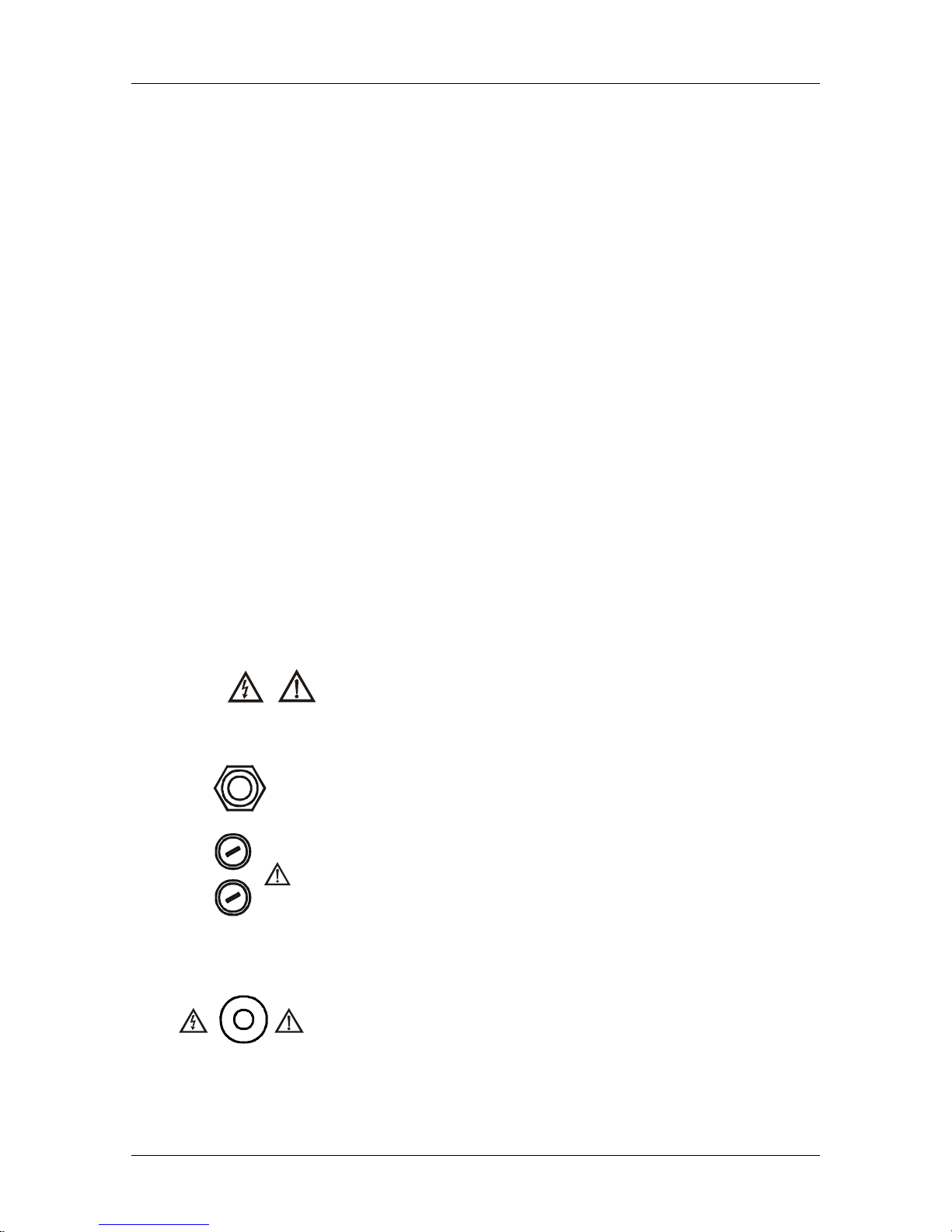
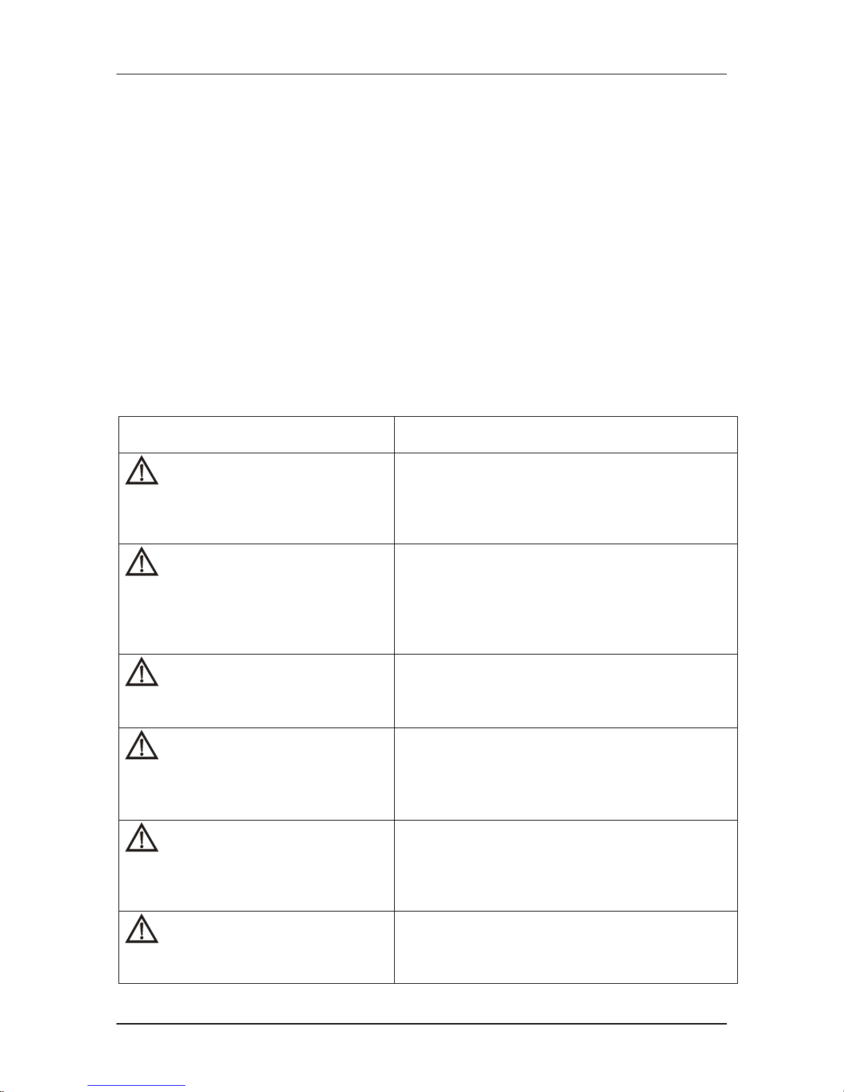
Meaning of , signs on front panel:
Input section ............................................ Sw itch off the instrument and disconnect all
test cables and mains cord before replacing
the fuses or opening the instrument
Flash terminal (MI2140 only)................... Dangerous voltage may be present.
Always handle as if the test leads are
energized.
FLASH
T16A/250V
T16A/250V
F1
F2
230V
50/60 Hz
16A
115V~/ ~
Page 6
MI 2140 MI 2140 Omega &BetaPAT General presentation
6
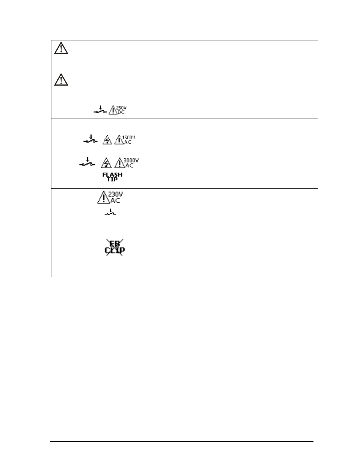
Other terminals........................................Disconnect all equipment from the
instrument during the test except for the
equipment under test.
IEC cord connector is for test purposes only;
do not connect it to mains supply!
Dangerous voltage is present on the test
sockets during the measurement.
Measurements should only be carried out on
de-energized appliances.
Test sockets are intended only for
connection of tested appliance!
Maximum output current of any of two test
sockets (230 V / 115 V) is 16 A.
1.2. Features
Portable appliance testers MI2140 and MI2141 are instruments intended for testing the
safety of portable electrical equipment.
General functions of MI2140 and MI2141:
- Visual test.
- Earth bond test.
- Insulation test.
- Substitute leakage test.
- Flash test (MI2140 only).
- Leakage test.
- Touch leakage test.
- Functional (power) test.
- IEC cord test.
Benefits of MI2140 and MI2141:
- Fast and reliable performance of all tests necessary for testing the safety
of portable appliances.
- Large graphic LCD display with resolution of 240 x 128 dots, with back-
light.
- Over 4000 memory locations in data flash memory.
- Two RS232C communication ports for communication with PC, bar code
reader or printer.
- Soft touch keyboard with cursor keys.
- Built in real time clock.
The instrument is supplied with all necessary accessories for carrying out the tests.
EARTH BONDIEC CORD
Page 7

MI 2140 MI 2140 Omega &BetaPAT General presentation
7
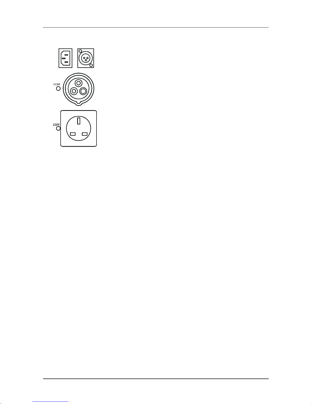
1.3. Connection
The tester may be powered with 115 V or 230 V supply voltage, and will test appliances
for both voltages (depending on supply voltage). LED indicator adjacent to the test
socket denotes which test socket is active.
The supply must include an earth connection.
1.4. Applied standards
Instrument operation:
- British standards BS 89,
- German standards VDE 0701 and VDE 0702.
Safety and electromagnetic compatibility (EMC):
- EN 61010 -1,
- IEC 61326.
Page 8
MI 2140 MI 2140 Omega &BetaPAT Instrument description
8
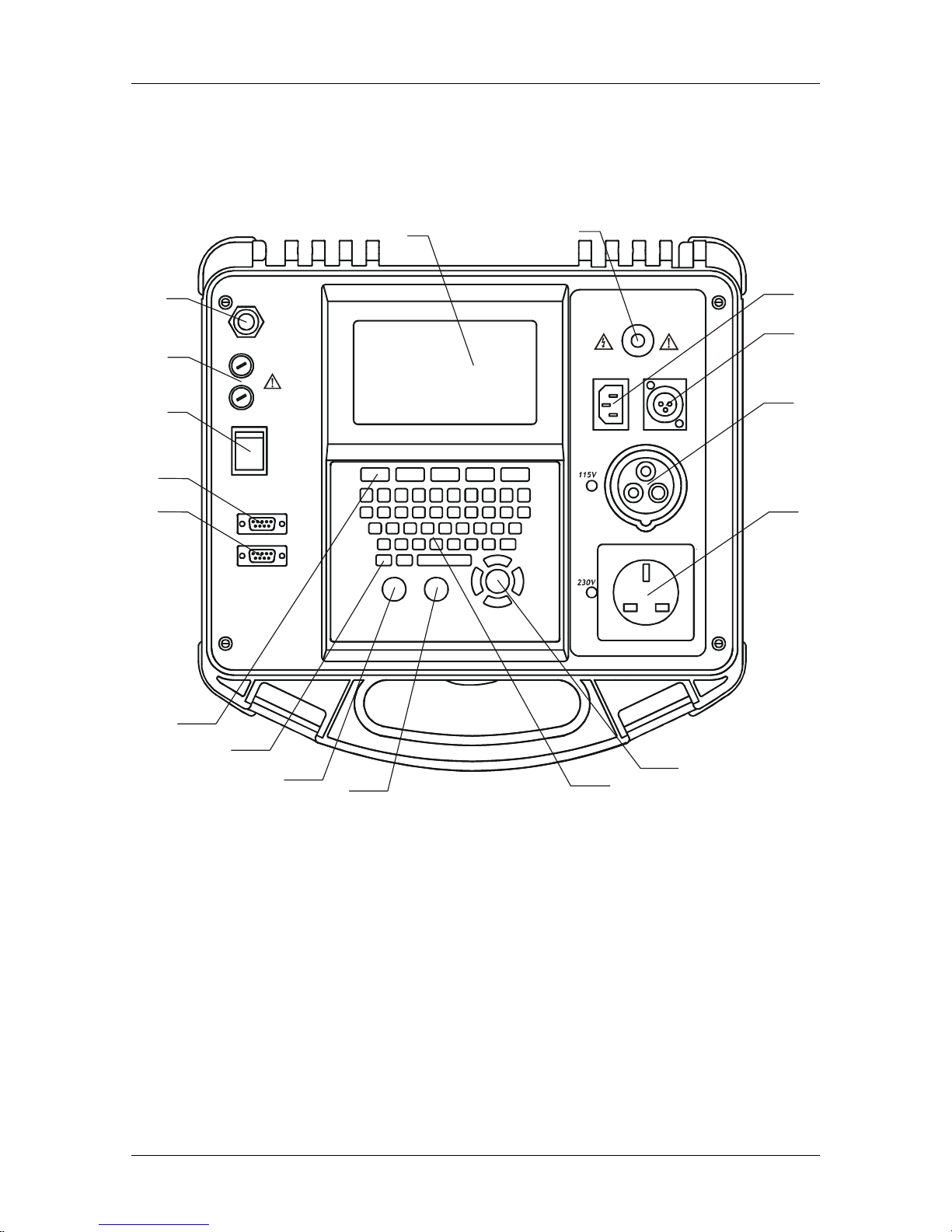
2. 2. Instrument description
2.1 Front panel description
T16A/250V
T16A/250V
F1
F2
230V
50/60 Hz
16A
115V~/ ~
RS232C
BARCODE / PRINTER
EARTH BONDIEC CORD
FLASH
1
2
3
4
5
6
7
8
9
10
11
12
13
17
16
14
15
Fig. 2.1 Front panel layout
Legend:
1. Power ON/OFF switch with indication lamp.
2. T 16A 250V fuses protect instrument power supply.
3. Mains supply.
4. Graphic LCD, 240 x 128 dots, with backlight.
5. Flash test terminal (MI2140 only).
6. IEC lead connector.
7. EARTH BOND connector, also used as touch leakage input for some Class II tests.
8. 115 V socket
9. 230 V socket
Page 9
MI 2140 MI 2140 Omega &BetaPAT Instrument description
9
10. Cursor keys:
• UP / DOWN key, to increase / decrease edited value,
• LEFT / RIGHT key, to move between edited values,
• ENTER key, to confirm selection in menu.
11. Keyboard.
12. STOP key.
13. START key.
14. ESC key, to return to previous page in menu.
15. Function keys, to set various parameters in each function. The purpose of a
specific key in each function is marked on display.
16. RS 232 connector for communication with a PC.
17. Barcode reader / printer connector.
2.2. Instrument messages
Description of displayed messages:
L and N are CROSSED.
Press Start to continue
Check the wiring of supply.
Mains voltage is not correct
or PE not connected.
Check Mains voltage and PE
connection!
Check for incorrect wiring of supply – there is no
earth connection or mains voltage is incorrect.
L-N RESISTANCE TOO HIGH
(>30 kΩ)
CHECK SWITCH OR FUSE
Do you wish to PROCEED
(Y/N)?
Resistance between L and N of appliance under
test is higher than 30 kΩ – check the appliance
power switch or fuse.
L-N SHORTED (< 3.0 Ω)
Do you wish to PROCEED
(Y/N)?
Resistance between L and N of appliance under
test is lower than 3 Ω - possible short-circuit or
high inrush current – check the appliance.
L-N RESISTANCE TOO LOW
( 8.0 Ω)
Do you wish to PROCEED
(Y/N)?
Resistance between L and N of appliance under
test is lower than 20 Ω - current may be higher
than 16 A – check the appliance.
LEAKAGE TOO HIGH
( >20.0mA)
Do you wish to PROCEED
(Y/N)?
Leakage current in pre-test is too high –
potential danger to operator and damage to
appliance if test is continued.
NAME OF TEST
Test was skipped for SAFETY
Potential hazardous tests were skipped because
one or more results were out of limit in
measurements of earth bond, insulation or
substitute leakage.
Page 10
MI 2140 MI 2140 Omega &BetaPAT Instrument description
10
VOLTAGE ON
SOCKET FROM APPLIANCE
Measurement is ABORTED
An external voltage is present on test socket –
check measurement circuit.
OVERHEATED
Measurement is ABORTED
The instrument was overheated during the
measurement of earth bond – allow the
instrument to cool down before proceeding with
the measurements.
High DC voltage between L-N and PE on test
socket (during insulation test).
(MI2140 only)
Presence of dangerous HV voltage during Flash
test.
1500V between L-N and PE on test socket
3000V between Flash terminal and L-N on test
socket.
Dangerous mains voltage on test socket (during
Leakage/Power and Touch Leakage tests).
Device under test must be switched on during
test
EB
CLIP
Use Earth Bond clip in this test.
Ensure that the Earth Bond clip is not connected
to any part of the appliance that may heat up or
rotate when switched on.
IEC
PLUG
Connect the lead to be tested to the IEC plug.
Note:
• The ‘L-N resistance too high’ message is shown if the L-N circuit pretest fails.
In this case it is recommended to check whether the power switch is switched on
and/or the mains fuse is not broken.
This pretest is performed:
- Before the first Insulation, SubLeakage, Leakage, Touch Leakage test in the
SINGLE TEST menu.
- Before the one test of Insulation, SubLeakage, Leakage, Touch Leakage (whichever
is selected first) in AUTOTEST – SHORTCUT and AUTOTEST – CUSTOM menus.
This pretest is skipped for Polarity test.
Page 11
MI 2140 MI 2140 Omega &BetaPAT Instrument description
11
3. 3. Technical specification
3.1 Earth bond test
Earth bond resistance (4 A, 10 A, 25 A)
Range R Resolution Accuracy (after calibration)
0.00 –1.99 Ω 0.01 Ω ±(5 % of reading + 3 digit)
2.00 –19.99 Ω 0.01 Ω ±10 % of reading
Earth bond resistance (100 mA)
Range R Resolution Accuracy (after calibration)
0.00 –1.99 Ω 0.01 Ω ±(5 % of reading + 3 digit)
Indication range: 2.00 –19.9 Ω
Test currents: 100 mA, 4 A, 10 A, 25 A into 100 mΩ at mains voltage of 240 VAC
Open circuit voltage: <6 VAC, (2.2 VAC at 100 mA) at U
mains
= 240 VAC
Limits: 0.01 - 0.09 Ω, 0.10 - 0.90 Ω, 1.00 - 9.00 Ω
Timer: 2 s, 3 s, 5 s, 10 s, 30 s
Output: EARTH BOND clip, 115 V or 230 V socket
3.2 Insulation test
Insulation resistance readout
Range Resolution Accuracy
0.000 – 0.500 MΩ 0.001 MΩ ±(10 % of reading + 5 digit)
0.500 –1.999 MΩ 0.001 MΩ
2.00 –19.99 MΩ 0.01 MΩ ±(5 % of reading + 3 digit)
20.0 – 199.9 MΩ 0.1 MΩ
Nominal voltage: 250 VDC, 500 VDC (-0 % / +10 %)
Nominal current: 1 mA @ 250 kΩ (250 V)
1 mA @ 500 kΩ (500 V)
Short circuit current: 2 mA max.
Limits: 0.50 MΩ, 1.00 MΩ, 2.00 MΩ, 4.00 MΩ, 7.00 MΩ, 10.0 MΩ, 50.0 MΩ
Auto discharging after test
Timer: 2 s, 3 s, 5 s, 10 s, 30 s
Output: 115 V or 230 V socket
Page 12
MI 2140 MI 2140 Omega &BetaPAT Instrument description
12
3.2 Substitute leakage test
Substitute leakage current readout
Range Resolution Accuracy
0.00 – 19.99 mA 0.01 mA
±(10 % of reading + 5 digit)
Short circuit current: < 30 mA
Open circuit voltage: 40 V AC
Displayed substitute current is calculated to 115 V, 230 V, depending on mains
voltage
Limits: 0.25 mA, 0.50 mA, 0.75 mA, 2.50 mA, 3.50 mA, 7.00 mA, 9.90 mA, 15.00 mA
Timer: 2 s, 3 s, 5 s, 10 s, 30 s
Output: 115 V or 230 V socket
3.3 Flash test (MI2140 only)
Flash current readout
Range Resolution Accuracy
0.00 - 2.50 mA 0.01 mA
±(5 % of reading + 5 digit)
Test voltage: 1500 VAC, 3000 VAC
Output resistance: 480 kΩ@1500 V, 960 kΩ@3000 V
Limits: 1 mA, 1.5 mA, 2.0 mA, 2.25 mA
Timer: 2 s, 3 s, 5 s, 10 s, 30 s
Output: For Class I appliance 115 V or 230 V sockets
For Class II appliance 115 V or 230 V sockets and Flash terminal
3.4 Leakage current and Power test
Differential leakage current readout
Range Resolution Accuracy
0.00 – 10.00 mA 0.01 mA
±(5 % of reading + 5 digit)
Threshold limits: 0.25 mA, 0.50 mA, 0.75 mA, 1.00 mA, 1.50 mA, 2.25 mA, 2.50 mA,
3.00 mA, 3.50 mA, 9.90 mA
Timer: 2 s, 3 s, 5 s, 10 s, 30 s, 60 s, 120 s, 180 s
Output: 115 V or 230 V socket
Page 13
MI 2140 MI 2140 Omega &BetaPAT Instrument description
13
Power readout
Range Resolution Accuracy
0.00 – 4.00 kVA 0.01 kVA
±(5 % of reading + 3 digit)
Timer: 2 s, 3 s, 5 s, 10 s, 30 s, 60 s, 120 s, 180 s
Output: 115 V or 230 V socket
3.5 Touch leakage current
Touch leakage current readout
Range Resolution Accuracy
0.00 – 1.99 mA 0.01 mA
±(10 % of reading + 5 digit)
Threshold values: 0.25 mA, 0.50 mA, 1.00 mA
Timer: 2 s, 3 s, 5 s, 10 s, 30 s, 60 s, 120 s, 180 s
Output: 115 V or 230 V socket
R
A-meter
: 2 kΩ
3.6.Polarity test
Test voltage: < 50 V
Output: 230 V / 115 V socket and IEC cord
Results: PASS, L-PE short, N-PE short, L-N short, L open, N open, PE open, N -PE
crossed, L-PE crossed, L-N crossed, MULTIPLE FAULT
Page 14
MI 2140 MI 2140 Omega &BetaPAT Instrument description
14
4. Measurements
4.1. Presentation of results
4.1.1. PASS / PASS * / FAIL result
Depending on the limit set in the selected test, the result is marked either with a PASS
or FAIL message. Limits are shown in the upper right corner of the display.
The message is always displayed as well as the actual measured result (except in
visual test).
A conditional PASS (PASS*) message is shown if one or more tests in the set Autotest
routine are skipped or aborted. In this case all performed tests must PASS. Otherwise,
FAIL is shown.
4.2. Manipulation
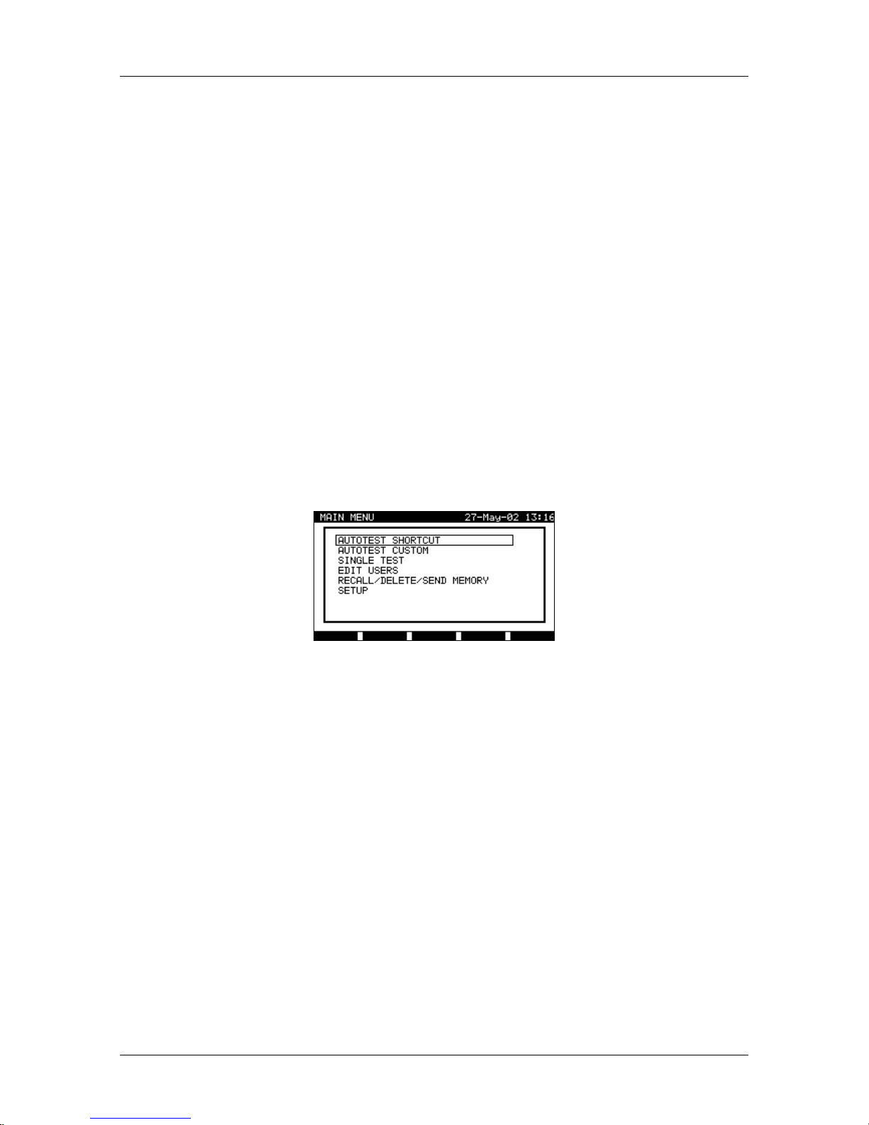
After start–up of the instrument, the MAIN MENU is displayed:
Fig. 4.1 Main menu
To select an option from the menu, use UP and DOWN keys. The selected option will
be highlighted. The selection is confirmed with the ENTER key. To return into MAIN
MENU from any sub-menu, press the ESC key.
4.2.1. Help option
In all measurements a help menu is available with connection diagram and instructions
on how to perform the test. Where there are two options (Class I or Class II appliance),
descriptions for both are available. The last page (or two) of the help menu provides
guidance on why a test may fail (e.g. connection problems). An example help menu for
earth bond measurement is presented in the following figures.
Page 15
MI 2140 MI 2140 Omega &BetaPAT Instrument description
15
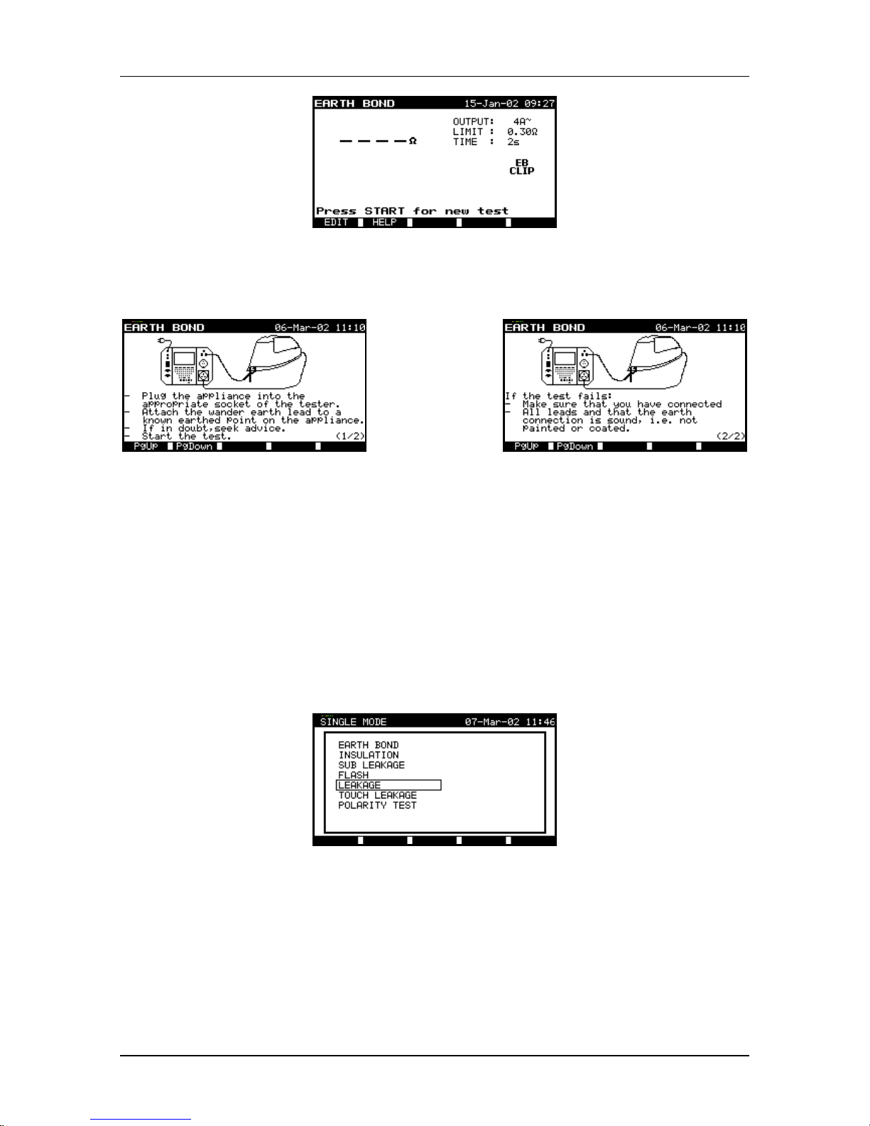
Fig. 4.2 Earth bond display example
→Press key F2 (HELP)→
Fig. 4.3 Help example for earth
bond test connection
→
Press
PgUp →
Fig. 4.4 Help for reasons of failed
earth bond test
4.3. Single mode
In single mode individual tests can be performed. This is suitable in cases when the
appliance fails in one or more tests. After repairing the appliance it is wise to retest that
particular function. In this mode it is not possible to save the result, because it is only
intended to check the effectiveness of the repair. After the successful repair the
complete appliance test has to be performed.
In single mode the SINGLE MODE menu is displayed:
Fig. 4.5 Single mode menu
To select an option from the menu, use the UP and DOWN keys. The selected option
will be highlighted. The selection is confirmed with the ENTER key. To return to the
previous menu, press the ESC key.
In every test it is possible to set measurement parameters. If the limits are saved, they
will be used for all future measurements in the single mode function. If they are not
saved and the measurement is started with the START key, the settings are used until
exit from the single mode function, then they are returned to the previous settings.
Page 16
MI 2140 MI 2140 Omega &BetaPAT Instrument description
16
4.3.1. Earth bond test
The purpose of this test is to ensure that the resistance of connections between the
earth wire in the mains supply plug and the grounded metal parts of an appliance is
below allowed limits. The resistance limit, duration of measurement, output current and
the number of measurements are selectable according to the requirements. Before
testing, check that the test will not cause any damage to the appliance. Test with a
maximum current of 100 mA is applied when higher current can cause damage. This is
often necessary when computers or other information technology appliances are
checked.
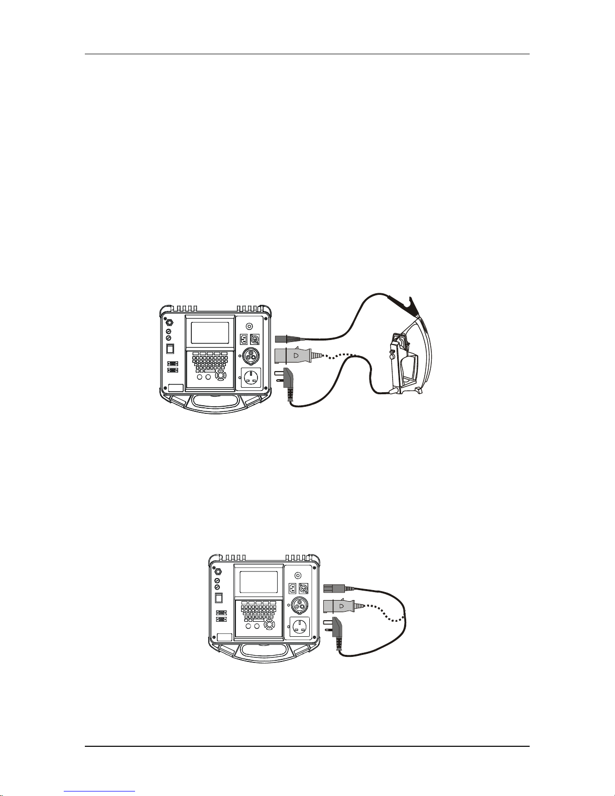
Earth bond test of Class I appliances
For Class I appliances the test voltage is applied between PE terminal (L and N line are
of no importance) and Earth Bond clip.
OR
A
PPLIANCE
UNDER
TEST
Fig. 4.6 Connection for Class I appliance
Earth Bond test of IEC leads
When testing IEC leads, the lead end should be connected to the IEC CORD terminal.
This is convenient when performing a complete IEC CORD test (no need for
reconnection during test, no need for adapters).
IEC CORD
UNDER
TEST
Fig. 4.7 Earth bond test of IEC cord
Page 17
MI 2140 MI 2140 Omega &BetaPAT Instrument description
17
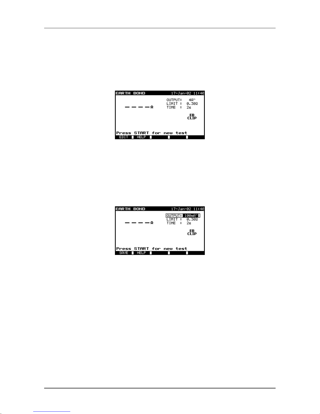
How to carry out single Earth Bond resistance measurement:
STEP 1. In the MAIN MENU window select SINGLE TEST and confirm with the
ENTER key.
STEP 2. In the SINGLE TEST window select EARTH BOND and confirm with the
ENTER key.
Fig. 4.8 Earth bond test initial display
STEP 3. The parameters of the measurement are detailed in the upper right corner of
the display. To change these parameters, first press the F1 (EDIT) key and
then use cursor keys to set relevant parameters. The selected limit is
changed with the UP and DOWN keys, movement between parameters is
possible with the LEFT and RIGHT keys. To save new limits press the F1
(SAVE) key. The test can now be performed.
Fig. 4.9 Selection of test current
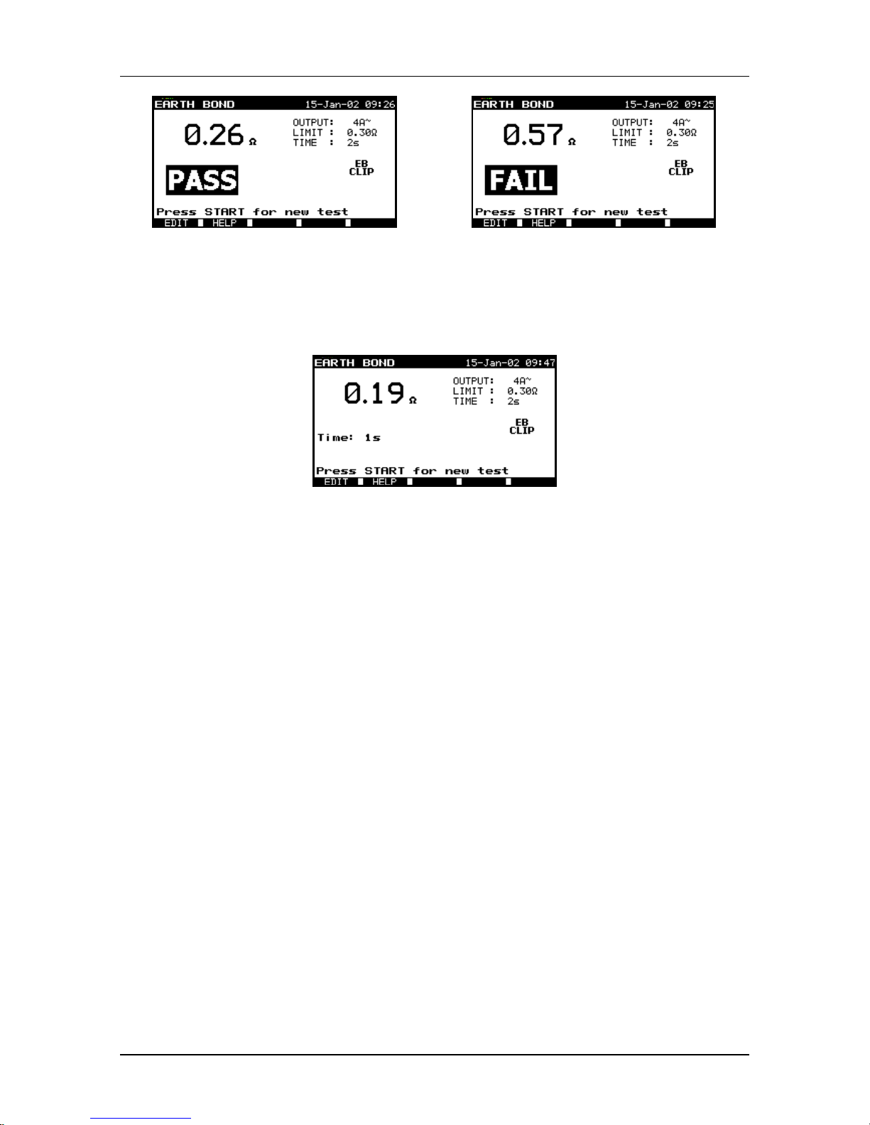
STEP 4. Press START key to perform the test.
STEP 5. PASS/FAIL result is shown on the display. Repeat the test with the START
key or return to SINGLE MODE main screen with the ESC key.
Page 18
MI 2140 MI 2140 Omega &BetaPAT Instrument description
18
Fig. 4.10 Good result example
Fig. 4.11 Bad result example
The test can be aborted with the STOP key at any time, but in such case there is no
PASS / FAIL decision.
Fig. 4.12 Indication of aborted measurement
Note:
• Consider any warning on the display (see Chapter 2.2) before starting
measurement.
4.3.2. Insulation test
The purpose of this test is to ensure that the insulation resistance between the live
conductors and the earth or metal parts of an appliance is within allowed limits. The test
voltage, resistance limit, duration of measurement and number of measurements are
selectable according to requirements.
Check to ensure that the appliance under test does not contain any over voltage
protection device, otherwise incorrect results could be obtained.
Insulation test of Class I appliances
For Class I appliances the test voltage is applied between the live pins (L and N are
shorted together in the tester) and the earth pin in an appliance mains plug.
Page 19

MI 2140 MI 2140 Omega &BetaPAT Instrument description
19
OR
CLASS
A
PPLIANCE
UNDER
TEST
I
Fig. 4.13 Connection of Class I appliance
Insulation test of Class II appliances
For Class II appliances (and non-earthed parts of Class I appliances), the test voltage is
applied between the live pins (L and N lines are shorted together in the tester) and the
earth bond test clip that is attached to the metal parts of the appliance.
Before testing, check that the test will not cause any damage to the appliance.
OR
CLASS
A
PPLIANCE
UNDER
TEST
II
Fig. 4.14 Connection of Class II appliance
Insulation test of IEC leads
When testing IEC leads, the lead’s end can be connected to the IEC CORD terminal.
This is recommended when performing a complete IEC CORD test (no need for
reconnection during test).
IEC CORD
UNDER
TEST
Fig. 4.15 Insulation test of IEC cord
Page 20

MI 2140 MI 2140 Omega &BetaPAT Instrument description
20
How to carry out single Insulation resistance measurement:
STEP 1. In MAIN MENU window select SINGLE TEST and confirm with the ENTER
key.
STEP 2. In the SINGLE TEST window select INSULATION and confirm with the
ENTER key.
STEP 3. The parameters of the measurement are detailed in the upper right corner of
the display. To change these parameters first press the F1 (EDIT) key and
then use cursor keys to set required parameters. The highlighted limit is
changed with the UP and DOWN keys, movement between parameters is
possible with the LEFT and RIGHT keys. To save new limits press the F1
(SAVE) key. The test can now be performed.
Fig. 4.16 Insulation test initial display
STEP 4. Press the START key to perform test.
STEP 5. PASS/FAIL result is shown on the display. Repeat the test with the START
key or return to SINGLE MODE main screen with the ESC key.
Fig. 4.17 Good result of insulation test
Fig. 4.18 Bad result of insulation test
The test can be aborted with the STOP key at any time, but in such case there is no
PASS / FAIL decision.
Page 21

MI 2140 MI 2140 Omega &BetaPAT Instrument description
21
Fig. 4.19 Indication of aborted measurement
Notes:
• The appliance under test should be de-energized before the test.
• Consider any warning on the display (see Chapter 2.2) before starting
measurement.
• Do not touch the equipment under test during the test or before it is fully
discharged. The message “Discharging” is on display whilst the voltage on
equipment under test is higher than 30 V.
• Do not disconnect the equipment under test from the instrument during the
measurement or before it is automatically discharged.
4.3.3. Substitute leakage test
The purpose of this test is to predict the leakage current at nominal mains voltage and
to avoid danger for both the operator and the appliance under test where there is a
faulty insulation or a connection between PE and mains. Substitute leakage current is
measured at a nominal voltage of 40 VAC and is scaled to a nominal mains voltage
(115 VAC or 230 VAC).
In some cases, when large suppression capacitors are connected between L and PE
line, substitute leakage current can differ from conventional leakage current.
Substitute leakage current test of Class I appliances
For Class I appliances, test voltage is applied between mains lines (L and N lines are
shorted together in the tester) and ground line.
OR
CLASS
A
PPLIANCE
UNDER
TEST
I
Fig. 4.20 Substitute leakage current test connection for Class I appliance
Page 22

MI 2140 MI 2140 Omega &BetaPAT Instrument description
22
Substitute leakage current test of Class II appliances
For Class II appliances earth bond test clip is used as a substitute for PE. Ensure that
the connected metal part is not in contact with external ground connection (see picture).
OR
CLASS
A
PPLIANCE
UNDER
TEST
II
Fig. 4.21 Substitute leakage current test connection for Class II appliance
How to carry out single Substitute leakage current measurement:
STEP 1. In the MAIN MENU window select SINGLE TEST and confirm with the
ENTER key.
STEP 2. In the SINGLE TEST window select SUB LEAKAGE and confirm with the
ENTER key.
STEP 3. The parameters of the measurement are detailed in the upper right corner of
the display. To change these parameters first press the F1 (EDIT) key and
then use cursor keys to select the required parameter. The highlighted limit is
changed with the UP and DOWN keys, movement between parameters is
possible with the LEFT and RIGHT keys. To save new limits press the F1
(SAVE) key. The test can now be performed.
Fig. 4.22 Substitute leakage current initial diaplay
STEP 4. Press the START key to perform test.
STEP 5. PASS / FAIL result is shown on the display. Repeat the test with the START
key or return to SINGLE MODE main screen with the ESC key.
Page 23

MI 2140 MI 2140 Omega &BetaPAT Instrument description
23
Fig. 4.23 Good result of substitute leakage
current test
Fig. 4.24 Bed result of substitute leakage
current test
The test can be aborted with the STOP key at any time, but in such case there is no
PASS / FAIL decision.
Fig. 4.25 Display of aborted substitute leakage current test
Note:
• Consider any warning on the display (see Chapter 2.2) before starting
measurement.
4.3.4. Flash test (MI2140 only)
The purpose of this test is to ensure that the insulation strength is high enough to
prevent breakdown. Insulation strength becomes significant when high transient
voltages are present on the mains supply.
Before applying the test, check that the components in the appliance can withstand test
voltage. IT appliances are especially sensitive.
Before testing, check that the test will not cause any damage to the appliance.
Flash test of Class I appliances
For Class I appliances the test voltage (1.5 kV
AC
) is applied between the live pins (L and
N are shorted together in the tester) and the PE pin in an appliance mains plug.
Page 24

MI 2140 MI 2140 Omega &BetaPAT Instrument description
24
OR
CLASS
A
PPLIANCE
UNDER
TEST
I
Fig. 4.26 Flash test connection for Class I appliance
Flash test of Class II appliances
For Class II appliances the test voltage (3 kVAC) is applied between mains pins (L and N
are shorted together in the tester) and the flash probe tip.
OR
CLASS
A
PPLIANCE
UNDER
TEST
II
Fig. 4.27 Flash test connection for Class II appliance
How to carry out single Flash measurement:
STEP 1. In the MAIN MENU window select SINGLE TEST and confirm with the
ENTER key.
STEP 2. In the SINGLE TEST window select FLASH and confirm with the ENTER
key.
STEP 3. The parameters of the measurement are detailed in the upper right corner of
the display. To change these parameters first press the F1 (EDIT) key and
then use cursor keys to select the required parameter. The highlighted limit is
changed with the UP and DOWN keys, movement between parameters is
possible with the LEFT and RIGHT keys. To save new limits press the F1
(SAVE) key. The test can now be performed.
Page 25

MI 2140 MI 2140 Omega &BetaPAT Instrument description
25
Fig. 4.28 Flash test initial display
STEP 4. Press the START key to perform test. A trip out occurs if the current exceeds
the set limit, followed by a 3 seconds buzzer warning.
STEP 5. PASS / FAIL decision is shown on the display. Repeat the test with the
START key or return to SINGLE MODE main screen with the ESC key.
Fig. 4.29 Flash test good result example
Fig. 4.30 Flash test bad result example
The test can be aborted with the STOP key at any time, but there is no PASS / FAIL
decision.
Fig. 4.31 Display of aborted flash test
Notes:
• Consider any warning on the display (see Chapter 2.2) before starting
measurement.
• Do not touch the equipment under test or the test leads during the test –
dangerous voltage is present.
Page 26

MI 2140 MI 2140 Omega &BetaPAT Instrument description
26
4.3.5. Leakage current and Power test
The purpose of this test is to determine the loss of L to N current into PE. Leakage
current is the difference between the current in L and N mains lines.
Regardless of whether the current leaks into the earth lead or an extra ground point, the
leakage test will show the true leakage current.
Also the Power consumption of the appliance is shown.
Leakage current and Power test of Class I appliances
OR
CLASS
A
PPLIANCE
UNDER
TEST
I
Fig. 4.32 Connection of Class I appliance for leakage current and power test
Leakage current and Power test of Class II appliances
OR
Fig. 4.33 Connection of Class II appliance for leakage current and power test
How to carry out single Leakage current and Power measurements:
STEP 1. In the MAIN MENU window select SINGLE TEST and confirm with the
ENTER key.
STEP 2. In the SINGLE TEST window select LEAKAGE and confirm with the ENTER
key.
STEP 3. The parameters of the measurement are detailed in the upper right corner of
the display. To change these parameters first press the F1 (EDIT) key and
then use cursor keys to set the required parameter. The highlighted limit is
changed with the UP and DOWN keys, movement between parameters is
possible with the LEFT and RIGHT keys. To save new limits press the F1
(SAVE) key. The test can now be performed.
Page 27

MI 2140 MI 2140 Omega &BetaPAT Instrument description
27
Fig. 4.34 Leakage current and power test initial display
STEP 4. Press the START key to perform test.
STEP 5. PASS/FAIL result is shown on the display. Repeat the test with the START
key or return to SINGLE MODE main screen with the ESC key.
Fig. 4.35 Good result example for leakage
current and power test
Fig. 4.36 Bad result example for leakage
current and power test
The test can be aborted with the STOP key at any time, but in such case there is no
PASS / FAIL decision.
Fig. 4.37 Display of aborted leakage current and power test
Notes:
• The appliance is connected to mains – hazardous voltage. Make sure that if
the tested appliance has any moving parts it is safely mounted or protected
to prevent possible danger to operator or damage to the appliance.
• Consider any warning on the display (see Chapter 2.2) before starting
measurement.
• Before performing the full test a pre-test is carried out using a low voltage
to ensure that the appliance can be safely powered up. These tests check
for any possible leakage current and resistance between L and N. If the
potential current (into PE or between L and N) is too high, a warning sign
as shown in chapter 2.2. is displayed.
EDIT
for new test
Page 28

MI 2140 MI 2140 Omega &BetaPAT Instrument description
28
4.3.6. Touch leakage current
The purpose of this test is to check what level of current would flow to ground if a
person touches a metal part of an appliance. The human body is simulated with a 2 kΩ
resistor.
The Earth Bond clip is used as the test probe.
Touch leakage current test of Class I appliances
OR
CLASS
A
PPLIANCE
UNDER
TEST
I
Fig. 4.38 Connection for touch leakage test of Class I appliance
Touch leakage current test of Class II appliances
OR
CLASS
A
PPLIANCE
UNDER
TEST
II
Fig. 4.39 Connection for touch leakage test of Class II appliance
How to carry out single Touch leakage current measurements:
STEP 1. In the MAIN MENU window select SINGLE TEST and confirm with the
ENTER key.
STEP 2. In the SINGLE TEST window select TOUCH LEAKAGE and confirm with the
ENTER key.
STEP 3. The parameters of the measurement are detailed in the upper right corner of
the display. To change these parameters first press the F1 (EDIT) key and
then use cursor keys to select the required parameter. The highlighted limit is
changed with UP and DOWN keys, movement between parameters is
possible with LEFT and RIGHT keys. To save the new limits press the F1
(SAVE) key. The test can now be performed.
Page 29

MI 2140 MI 2140 Omega &BetaPAT Instrument description
29
Fig. 4.40 Touch leakage test initial display
STEP 4. Press the START key to perform test.
STEP 5. PASS / FAIL result is shown on the display. Repeat the test with the START
key or return to SINGLE MODE main screen with the ESC key.
Fig. 4.41 Good result example of touch
leakage test
Fig. 4.42 Bad result example of touch
leakage test
The test can be aborted with STOP key at any time, but in such case there is no PASS /
FAIL decision.
Fig. 4.43 Display of aborted touch leakage current test
Notes:
• The appliance is connected to mains – hazardous voltage. Make sure that if
the tested appliance has any moving parts it is safely mounted or protected
to prevent possible danger to operator or damage to the appliance.
• Consider any warning on the display (see Chapter 2.2) before starting
measurement.
• Before performing the full test a pre-test is carried out using a low voltage
to ensure that the appliance can be safely powered up. These tests check
for any possible leakage current and resistance between L and N. If the
potential current (into PE or between L and N) is too high, a warning sign
as shown in chapter 2.2. is displayed.
Page 30

MI 2140 MI 2140 Omega &BetaPAT Instrument description
30
4.3.7. Polarity test
The purpose of this test is to check the continuity and polarity of the mains supply cable.
Following faults are detected: L-PE shorted, N-PE shorted, L-N shorted, L open, N
open, PE open, N-PE crossed, L-PE crossed, L-N crossed, multiple fault.
IEC CORD
UNDER
TEST
Fig. 4.44 Connection of IEC cord for polarity test
How to carry out Polarity test:
STEP 1. In the MAIN MENU window select SINGLE TEST and confirm with the
ENTER key.
STEP 2. In the SINGLE TEST window select POLARITY and confirm with the ENTER
key.
Fig. 4.45 Polarity test initial display
STEP 3. Press the START key to perform test.
STEP 4. PASS / FAIL result is shown on the display. In case of a FAIL result
explanation is displayed under the decision. Repeat the test with the START
key or return to SINGLE MODE main screen with the ESC key.
Page 31

MI 2140 MI 2140 Omega &BetaPAT Instrument description
31
Fig. 4.46 Good result of polarity test
Fig. 4.47 Bad result of polarity test
Note:
• Consider any warning on the display (see Chapter 2.2) before starting
measurement.
4.4. Autotest
Autotest is the fastest and easiest way to test and certify appliances. A pre-programmed
sequence leads the user through the tests needed for verifying the appliance. Different
pre-programmed test procedures can be selected in each of the two autotest menus.
4.5. Autotest - shortcut
In this menu the user can choose between over 120 types of preselected test
procedures. The preprogrammed sequences covers practically all in-service tests,
regardless of appliance type, class, supply cord length, fuse size, etc.
All limits and tests are in accordance with currently valid standards and regulations. In
case of any changes new firmware (with new standards and limits) is available on-line
at your distributor or from Metrel directly.
Fig. 4.48 Example for Autotest of
appliance
Fig. 4.49 Example for Autotest of
extension cord
The AUTOTEST SHORTCUT can be easily selected:
- by setting the few displayed parameters,
- by entering the three number autotest code,
- by using the barcode reader,
and then started with the START key.
Page 32

MI 2140 MI 2140 Omega &BetaPAT Instrument description
32
Two autotest shortcut examples are shown in the pictures above.
The complete list of measurements and codes can be found in Appendix 1 at the end of
this manual.
For operation of a barcode reader see chapter 5.2.
APPLIANCE TYPE
Portable or Handheld Appliances
IT (Information Technology) equipment (EN60950)
Heating and Cooking Appliances
Other appliances
Extension leads
Most electrical appliances belong to one of these types. The tests and limits differ
slightly depending on the specific regulation.
In general the following tests have to be performed during an in service test:
Class I equipment: VISUAL CHECK, EARTH BOND TEST, INSULATION TEST,
FUNCTIONAL TEST.
Class II equipment: VISUAL CHECK, INSULATION TEST, FUNCTIONAL TEST.
Notes:
• For portable and handheld appliances the Leakage (or Touch Leakage) limits are
stricter than for other types.
• For IT equipment the Earth Bond test is performed with low current (100 mA) in
order to avoid any damage to earth connections for EMC (screening) purposes.
• For cooking and heating appliances the Leakage limit is set higher because
some of leakage typically occurs in the heating elements. Therefore the
substitute leakage test is performed instead of insulation test.
• Only three conductor extension leads are considered and they are tested as a
Class I appliance. When testing them the Functional test and the Polarity test are
performed.
• The IT equipment must conform to the EN60950 regulation. Otherwise the
equipment may be damaged during the insulation test!
APPLIANCE CLASS
Class I
Class II
SUPPLY CORD
Short
Middle (or low c.s.a)
Long
Notes:
• The Earth Bond limit depends significantly on the supply cord length and its PE
wire cross-section.
• SHORT should be set for appliances with a cord not longer than 5 m.
• MEDIUM can be used when the appliance's supply cord is longer than 5 m or the
cord's wire has a small cross-section.
Page 33

MI 2140 MI 2140 Omega &BetaPAT Instrument description
33
• LONG can be used if the appliance has a very long supply cord (for instance, for
vacuum cleaners the cord is longer than 15 m).
APPLIANCE FUSE
3 A (750 VA), 6 A (1.5 kVA), 10 A (2.5 kVA), 13 A (3.2 kVA)
Notes:
• The Earth Bond test current depends on the set fuse rating of appliance. The
current is always at least 1.5 times higher than the fuse ratting.
• The power (in brackets) means the maximum power that can be delivered in
combination with the set fuse. Some users are more familiar with the nominal
power than the fuse size.
• Substitute Leakage and Leakage current limits (in Heating and cooking) are set
according to the set power.
FUNCTIONAL TEST / PROTECTIVE EARTH TEST
YES, NO
Notes:
• A functional test should be performed at the end of the test sequence to assure
that the appliance works properly. This test can also be performed without the
measuring instrument.
• However it is a good practice to perform this test with the OmegaPAT or
BetaPAT, because it makes more tests simultaneously: the functional check, the
Protective Earth test and Load test.
Extension leads test only:
LENGTH
<5 m, 7.5 m, 10 m, 12 m, 15 m, 20 m, 30 m, 40 m, 50 m
CROSS-SECTION AREA (c.s.a.)
0.5 mm
2
, 0.75 mm2, 1.0 mm2, 1.25 mm2, 1.5 mm2, unknown
MAXIMUM CURRENT CAPABILITY, POWER (Imax / Power)
3 A / 750 VA, 6 A / 1.5 kVA, 10 A / 2.5 kVA, 3 A / 3.2 kVA, 15 A / 3.75 kVA,
unknown
Notes:
• If the cross-section area is unknown the most conservative (as for 1.5mm2) limit
is set.
• The Imax / Power is only informative. It provides the maximal current capability
and power depending on the lead’s c.s.a.
Page 34

MI 2140 MI 2140 Omega &BetaPAT Instrument description
34
CODE
Each of the possible test combinations has its own three-number code. By entering the
three-digit code the appropriate test will be set.
The parameters of the selected autotest (enabled tests, limits, and duration) can be
viewed by pressing the F1 (VIEW) key.
Fig. 4.50 Autotest parameter verification
By pressing the UP and DOWN keys the settings (function enabled/disabled, duration,
limit) for individual functions can be seen in a frame in the right part of the display.
Unlike in the AUTOTEST CUSTOM menu the settings cannot be saved or altered.
Refer to chapter 4.6 for more information.
When pressing the F3 (SAVE AS) key it is possible to copy the settings (parameters) in
the AUTOTEST CUSTOM menu where the test data can be changed and renamed
(refer to chapter 4.6 for further information).
When pressing the F1 key (BACK) the instrument returns to the main AUTOTEST
SHORTCUT menu.
The autotest can be started directly from both described menus.
Note:
• It could happen that none of the offered autotests in this menu corresponds (for
instance when testing against stricter limits in end of production line testing or
after repair testing, if performing flash tests etc). In this case it is recommended
to use the AUTOTEST – CUSTOM menu. From this menu, any autotest
combination can be set (see chapter 4.6).
4.6. Autotest – custom
In the autotest – custom the user can set his own test procedures, store and name them
in a list.
When setting this option the AUTOTEST – CUSTOM main menu will be displayed.
If more than one procedure is stored they can be selected with the UP and DOWN keys.
The selected procedure will be shown in a frame. The selection is confirmed with the
ENTER key.
Page 35

MI 2140 MI 2140 Omega &BetaPAT Instrument description
35
Fig. 4.51 Example of preparing custom test
The parameters of the selected procedure (enabled tests, limits, and duration) can be
viewed by pressing the F1 (VIEW) key.
By pressing the UP and DOWN keys individual measurement settings (function
enabled/disabled, duration, limit) can be seen in the right of the display.
Viewing / changing of custom test procedures:
Pressing the F4 (EDIT) key enables changing of parameters:
MODE
Disabled, Single, Continuous
In Disabled is set the function will be skipped in autotest.
In Single (Enabled in Visual Test) the test will be performed once in the autotest.
If Continuous is set more than one of the selected tests can be performed. During the
autotest the user will be asked whether to make a new test (of the same measurement)
or proceed to the next function.
OUTPUT
Test voltages and currents can be set here, depending on the selected
measurement.
LIMIT
Test limits can be set here, depending on the selected measurement.
TIME
Test durations can be set here, depending on the selected measurement.
New settings can be confirmed with the F1 (CONFIRM) key. If not saved the changes
will stay only for one (next) autotest. Setup can be exited without any change by using
the ESC key.
Page 36

MI 2140 MI 2140 Omega &BetaPAT Instrument description
36
Fig. 4.52 Parameter modification example
of selected autotest
Fig. 4.53 Confirmed parameters
Adding a new custom test procedure to the list
By pressing the F3 (SAVE AS) key it is possible to save the selected settings
(parameters) and adding them to the end of the list in autotest – custom main menu.
The instrument will ask for the name. The entered name is confirmed with the F1
(SAVE) key. The old name can be recalled with the F2 (UNDO) key.
Changing / renaming of existing custom test procedures
When pressing the F2 (SAVE) key it is possible to save the selected settings
(parameters). The instrument will ask for the name. The existing name can be left or
changed. The entered name is confirmed with the F1 (SAVE) key. The old name can be
recalled with the F2 (UNDO) key.
Deleting of existing custom test procedures
When pressing the F3 (DELETE) key in the main autotest – custom menu the selected
test procedure will be deleted. The instrument will ask for confirmation.
Notes:
• The test in the first line of the list cannot be deleted.
• The autotest can be started directly from both described menus (Main and
Parameters-View).
4.7. Performing of autotests
The following actions can be taken during any measurement:
F5 (END) key: end appliance test
F4 (SKIP) key: skip (do not perform) the selected test
START key: entering the autotest or
proceed with next function* or
perform a new test
F3 (REPEAT) key: repeat the measurement (except in visual check)
STOP key: abort the measurement
ENTER key: proceed with next function**
*) if single mode is selected
**) if continuous mode is selected
Page 37

MI 2140 MI 2140 Omega &BetaPAT Instrument description
37
If the measurement is skipped (before the measurement, after aborting it or after
completion) it will be internally treated as a FAIL result (to assure safety for the user).
If a FAIL result is given (due to a FAIL or skipped Earth Bond/Insulation/Substitute
Leakage test) the Flash/Leakage/Touch leakage measurements will be skipped to
ensure safety. The Polarity test will be performed in any case.
Visual check
The purpose of a visual check is to identify any visual damage to the case or cable of an
appliance. The external casing of the appliance must be carefully checked. Check also
that the mains fuse is the correct rating for the appliance.
APPLIANCE
UNDER
TEST
Fig. 4.54 Appliance inspection
Fig. 4.55 Items of appliance inspection
Check the required points and confirm correct result with function keys F1 to F5.
If everything is in good order the user can confirm all items with F2 (PASSall) key.
Earth bond measurement
Check the connections and consider the warnings on the display (EB CLIP, appliance
switched on). If testing an IEC lead connect the lead end to the IEC terminal.
Fig. 4.56 Earth bond test waiting for right connection
After performing the measurement one of the following displays will be shown indicating
the result.
Page 38

MI 2140 MI 2140 Omega &BetaPAT Instrument description
38
Fig. 4.57 Good result
Fig. 4.58 Bad result
Fig. 4.59 Aborted test
If the test passes, the instrument automatically proceeds with the Insulation test or
Substitute Leakage test (if applied and if in single mode).
Pressing the START key will move to the next function (single mode) or a new earth
bond test (continuous mode).
Pressing the F2 (HELP) key will display the HELP menu.
Pressing the F3 (REPEAT) key will repeat the test
Pressing the F4 (SKIP) key will skip the test and move to the next test.
Pressing the F5 (END) key will end (abort) the test.
Insulation measurement
Consider any displayed warnings (output voltage, appliance switched on). If testing a
Class II appliance use the earth bond clip as the second measurement probe.
If testing an IEC lead, connect the lead end to the IEC lead terminal.
Fig. 4.60 Insulation test waiting for right connection
After performing the measurement one of the following displays will be shown indicating
the result.
Fig. 4.61 Good result
Fig. 4.62 Bad result
Fig. 4.63 Aborted test
If the test passes, the instrument automatically proceeds with Substitute Leakage test (if
applied and if in single mode).
Page 39

MI 2140 MI 2140 Omega &BetaPAT Instrument description
39
Pressing the START key will move to the next function (single mode) or a new
insulation test (continuous mode).
Pressing the F2 key will display the HELP menu.
Pressing the F3 key will repeat the test.
Pressing the F4 key will skip the test and move to the next test.
Pressing the F5 key will end (abort) the test.
Substitute leakage test
Consider any displayed warnings (switch appliance on). If testing a Class II appliance
use the earth bond clip for the second measurement probe.
Fig. 4.64 Substitute leakage current test waiting for right connection
After performing the measurement one of the following displays will be shown indicating
the result.
Fig. 4.65 Good result Fig. 4.66 Bad result Fig. 4.67 Aborted test
Pressing the START key will move to the next function (single mode) or a new
subleakage test (continuous mode).
Pressing the F2 key will display the HELP menu.
Pressing the F3 key will repeat the test.
Pressing the F4 key will skip the test and move to the next test.
Pressing the F5 key will end (abort) the test.
Flash test (MI2140 only)
This test is only allowed if the previous measurements (Insulation / Earth Bond /
Substitute Leakage) have passed. If any one of them has failed or been skipped the
measurement is skipped.
Consider any displayed warnings (Dangerous - HIGH output voltage, switch appliance
on).
If testing a Class II appliance use the Flash probe as the second measurement probe.
Page 40

MI 2140 MI 2140 Omega &BetaPAT Instrument description
40
Fig. 4.68 Flash test waiting for right connection
After performing the measurement one of the following displays will be shown indicating
the result.
Fig. 4.69 Good result Fig. 4.70 Bad result Fig. 4.71 Aborted test
The test can only proceed if the Flash test has passed. If not the appliance test is
finished.
Pressing the START key will move to the next function (single mode) or a new flash test
(continuous mode).
Pressing the F2 key will display the HELP menu.
Pressing the F3 key will repeat the test.
Pressing the F4 key will skip the test and move to the next test.
Pressing the F5 key will end (abort) the test.
Leakage current and power test
This test is only allowed if previous measurements (Insulation / Earth Bond / Substitute
Leakage/Flash) have passed. If any one of them has failed or been skipped the
measurement is skipped.
Consider any displayed warnings (mains output voltage, switch appliance on, remove
EB CLIP’).
Fig. 4.72 Leakage current test waiting for right connection
After performing the measurement one of the following displays will be shown indicating
the result.
Page 41

MI 2140 MI 2140 Omega &BetaPAT Instrument description
41
Fig. 4.73 Good result Fig. 4.74 Bad result Fig. 4.75 Aborted test
The test can only proceed if the Leakage/Power test has passed. If not the appliance
test is ended.
Pressing the START key will move to the next function (single mode) or a new leakage
test (continuous mode).
Pressing the F2 key will display the HELP menu.
Pressing the F3 key will repeat the test.
Pressing the F4 key will skip the test and move to the next test.
Pressing the F5 key will end (abort) the test.
Touch leakage current
The test can only proceed if the previous measurements (Insulation / Earth Bond /
Substitute Leakage/Flash/Leakage) have passed. If at least one of them has failed or
been skipped the measurement is skipped.
Consider any displayed warnings (mains output voltage, appliance switched on, use EB
CLIP).
Fig. 4.76 Touch leakage current test waiting for right connection
After performing the measurement one of the following displays will be shown indicating
the result.
Fig. 4.77 Good result Fig. 4.78 Bad result Fig. 4.79 Aborted test
Pressing the START key will move to the next function (single mode) or a new touch
leakage test (continuous mode).
Pressing the F2 key will display the HELP menu.
Page 42

MI 2140 MI 2140 Omega &BetaPAT Instrument description
42
Pressing the F3 key will repeat the test.
Pressing the F4 key will skip the test and move to the next test.
Pressing the F5 key will end (abort) the test.
Continuation is allowed only if the Touch Leakage test has passed. If not the appliance
test is ended.
Polarity
Fig. 4.80 Waiting for cord connection
After performing the measurement one of the following displays will be shown indicating
the result.
Fig. 4.81 Good result
Fig. 4.82 Bad result
Pressing the START key will end the test.
Pressing the F2 key will display the HELP menu.
Pressing the F3 key will repeat the test.
Pressing the F5 key will end (abort) the test.
Page 43

MI 2140 MI 2140 Omega &BetaPAT Instrument description
43
4.8. Storing autotest results
After completing the appliance test the SAVE RESULT display will appear.
Fig. 4.83 Save result menu
By using the keyboard the user can enter all relevant details, such as number and name
of appliance, building, room, repair code and desired comments (the user is predefined
in the EDIT USERS menu – see chapter 5.3). To select the required line, use the UP
and DOWN keys.
Pressing the F2 (UNDO) key will return the previous content in the selected data line.
By pressing the F5 (LIST) key the user can choose a name from predefined name lists.
APPLIANCE NUMBER
Appliance number: any alphanumeric character can be used in this field. Appliance
number can be read directly with a Bar Code Reader. This data is obligatory for storing
any appliance test.
BUILDING
Any alphanumeric character can be used in this field.
It is possible to choose building data from a pre-set list of buildings – SELECT
BUILDING menu. Up to 60 predefined names can be pre-set in this menu.
ROOM
Any alphanumeric character can be used in this field.
It is possible to choose data from a pre-set list of rooms – SELECT ROOM menu. Up to
60 predefined names can be pre-set in this menu.
USER
The user is predefined in EDIT USERS menu – (see chapter 5.3).
APPLIANCE NAME
Any alphanumeric character can be set in this line.
It is possible to choose the appliance data from a pre-set list of names – SELECT
APPLIANCE menu. Up to 60 predefined names can be prepared in this menu.
RETEST PERIOD
In retest period a predefined period for retesting of appliances can be entered.
REPAIRING CODE
Repair code is a short, predefined code used in connection with some PC SW
packages.
Page 44

MI 2140 MI 2140 Omega &BetaPAT Instrument description
44
COMMENT
Any desired comments can be added in this field.
Pressing the F1 (SAVE) will save the measurements into memory. After saving the
results the instrument returns to the PERFORM APPLIANCE TEST display.
Pressing the F3 (SEND): the instrument goes into SEND RESULTS menu. From this
menu, the appliance test results can be printed out or downloaded to PC. Refer to
chapter Recall/Delete/Send memory for more information.
Pressing the F4 (VIEW) key will display all results and data in the same format, as they
will be stored.
Pressing the ESC key will return to the PERFORM APPLIANCE TEST display without
saving the results.
How to choose a name from the pre-set building/room/appliance list:
An example of how to use pre-set appliance names is shown below. The procedure is
identical for both buildings and rooms.
Press the F5 (LIST) key and select the name. Press the F1 (EDIT) key to change the
set name. The new name is confirmed with the SAVE or cancelled with the UNDO key.
Fig. 4.84 Predefined appliance names
Fig. 4.85 Custom appliance name
Page 45

MI 2140 MI 2140 Omega &BetaPAT Instrument operation
45
5. Instrument operation
5.1. Setup
It is advisable to create some settings before starting to use the instrument. This is done
in the SETUP function.
Fig. 5.1 Set-up menu
From the MAIN MENU window select SETUP and confirm with the ENTER key.
5.1.1. Set date and time
Date and time are attached to the results in the memory.
Select DATE/TIME with the ENTER key. Date is highlighted and can be changed with
the UP and DOWN keys, moving between the parameters is possible using the LEFT
and RIGHT keys. To save the new limits, press the F1 (SAVE) key, with the F2 (UNDO)
key it is possible to reset the previous value (in the case of a wrong entry) and using the
ESC key leaves these settings unchanged.
Fig. 5.2 Date / time setting
5.1.2. Set language
Select LANGUAGE with the ENTER key and select the desired language with the UP
and DOWN keys. To save the new language press the ENTER key, to leave these
setting without any changes press the ESC key.
Page 46

MI 2140 MI 2140 Omega &BetaPAT Instrument operation
46
Fig. 5.3 Language selection
5.1.3. Set print header
Select PRINT HEADER with the ENTER key and change it by pressing the F1 (EDIT)
key. Use the alphanumeric keyboard to enter all the desired data. Pressing the F1
(SAVE) key will save the data, by pressing the F2 (UNDO) key it is possible to reset the
previous values and using the ESC key leaves these settings unchanged.
Fig. 5.4 Set-up of printing header
Fig. 5.5 Editing of printing header
5.1.4. Instrument data
In this menu the instrument data is shown. No changes are possible.
Fig. 5.6 Information of the instrument
5.1.5. Set Contrast
Select CONTRAST using the ENTER key. Percentage number is highlighted and by
using the UP and DOWN keys the optimal contrast on the display can be set. To save
new value press the F1 (SAVE) key. By pressing the F2 (UNDO) key it is possible to
reset the previous value and using the ESC key leaves these settings without any
changes.
Page 47

MI 2140 MI 2140 Omega &BetaPAT Instrument operation
47
Fig. 5.7 Contrast modification
5.1.6. Original settings
In this menu the configuration can be reset to the values set when the tester was first
purchased.
Select ORIGINAL SETTINGS with the ENTER key. By pressing the Y key the reset is
confirmed, by pressing the N or ESC key the reset is cancelled.
Fig. 5.8 Restoring original settings
Instrument settings and measurement parameters and limits are set to their initial
values as follows:
Menu
Sub-menu
Default setting(s)
SINGLE TEST
Earth bond…………………………………………
Output: 25 A
AC
Limit: 0.30 Ω
Time: 5 s
Insulation…………………………………………... Output: 250 VDC
Limit: 10.00 MΩ
Time: 5 s
Sub
leakage…………………………….………….
Limit: 0.25 mA
Time: 5 s
Flash……………………………………………….. Limit: 1.00 mA
Time: 5 s
Leakage……………………………………………. Limit: 0.25 mA
Time: 5 s
Touch
leakage………………………….………….
Limit: 0.50 mA
Time: 10 s
AUTOTEST CUSTOM
TEST1-TEST8, all measurements disabled
EDIT USERS
USER1-USER15
Page 48

MI 2140 MI 2140 Omega &BetaPAT Instrument operation
48
5.1.7. Password
In password protected actions it is necessary to insert the password before deleting or
editing the protected data. The instrument requires a password and it will not allow
changes unless the correct password is entered.
Select PASSWORD with the ENTER key.
The typed password is entered with the ENTER key and pressing the ESC key will
leave these setting unchanged.
Please take a note of this password and keep it in a safe place.
Fig. 5.9 Entering a new password
→
Fig. 5.10 Confirmation of the new
password
If there is no password protection the instrument will request that you enter a new
password twice, once for confirmation.
If the instrument is already password protected, then the instrument will request the old
password before entering the new one twice, once for confirmation.
Fig. 5.11 Disabling existing password
To disable the password protection, instead of entering a new password just press the
ENTER key when asked for a new password and confirmation and the password will be
disabled.
If you forget the password, contact your dealer.
Password protected actions:
- Entering EDIT USER menu
- Entering EDIT MEASUREMENTS menu
- Deleting stored results
- Entering ORIGINAL SETTINGS menu
Page 49

MI 2140 MI 2140 Omega &BetaPAT Instrument operation
49
5.2. Autotests controlled by test code (use of barcode reader)
In the Autotest – Shortcut menu it is possible to set the testing procedure by test code.
By using the keyboard or a barcode reader it is possible to set the three number test
sequence for an appliance test.
To select a desired code select CODE and use the LEFT and RIGHT keys. When
pressing the ENTER key the code number can be entered directly with the keyboard.
In both cases the settings are displayed on-line.
No confirmation is needed to adopt the setting.
It is also possible to enter the code with an approved barcode reader (connected to
BARCODE / PRINTER connector).
BARCODE
READER
Fig. 5.12 Bar code reader connection
If the test code is accepted the instrument confirms the editing by changing the test
code and emitting two short ‘beeps’. If the test code is not correct the instrument does
not change the test code and warns the user with a long ‘beep’.
Start the measurement with the START key.
See the meaning of test code numbers in appendix 1.
5.3. Edit users
If more than one user uses the instrument, you can pre-set each users name to
distinguish the saved records by the each users name.
Fig. 5.13 User name selection
In the menu SET USERS it is possible to set 15 different users. By pressing the F1
(EDIT) key each user name can be set. The typed user name is confirmed by pressing
the F1 (SAVE) key.
Page 50

MI 2140 MI 2140 Omega &BetaPAT Instrument operation
50
Fig. 5.14 User name modification
By pressing the F2 (UNDO) key it is possible to reset the previous values and using the
ESC key leaves these settings unchanged. After saving the name(s) of the user(s),
select the temporary user by highlighting the appropriate name and confirming it by the
ENTER key.
5.4. Recall / Delete / Send memory
Searching and recalling memory
After entering RECALL/DELETE/SEND MEMORY menu, the SEARCH MEMORY menu
will be displayed.
Fig. 5.15 Memory search menu
It is possible to search all saved results, some of them or just one by means of five
special filters. Each of them can be set to search results according to appliance,
building, room, date and user. Individual filters can be enabled or disabled.
Operation of filters
All filters of the same type are combined together.
Example 1:
Fig. 5.16 Date filters
Page 51

MI 2140 MI 2140 Omega &BetaPAT Instrument operation
51
All results obtained in year 2001 and 2003 will be found.
All filters of different type will narrow search results.
Example 2:
Fig. 5.17 Adding user filter
All results of User 1, obtained in year 2001 and 2003 will be found. Other users won’t be
considered.
Setting of filter type
After pressing the F3 (TYPE) key the filter type will be highlighted. It can be set or
switched off with the LEFT and RIGHT keys. With the UP and DOWN keys other filters
can be selected.
Filter types are:
APPLIANCE, BUILDING, ROOM, DATE, USER
The ‘----‘ sign means that the filter is disabled.
Fig. 5.18 Example of main filters
Setting of filter content
By pressing the F5 (LIST) key the user can choose a name from the predefined name
lists (see chapter 4.8 for more information). For inserting appropriate data, use
keyboard. To find all results just enter “*” instead of names. Start searching by pressing
the F1 (FIND) key.
Page 52

MI 2140 MI 2140 Omega &BetaPAT Instrument operation
52
Fig. 5.19 Additional content filter
After completion of the search the RECALL MEMORY menu is shown, where it is
possible to see the overall result for each measurement. To see test results for the
selected appliance press the ENTER key and return back with the ESC key.
For listing other results, press the UP / DOWN keys or the F1, F2 (PgUp, PgDown) keys
Fig. 5.20 Find result codes for predefined filters
After pressing the ENTER key the selected result is shown in full detail. Use the F1
(PgUp), F2 (PgDown), F5 (MORE) or F5 (RESULT) keys to see complete result data.
Fig. 5.21 Stored result of
particular appliance code
→ F5 →
Fig. 5.22 Appliance Information
with particular code
Note: ‘S’ means STATUS, ’P’ means PASS, ‘F’ means FAIL
Page 53

MI 2140 MI 2140 Omega &BetaPAT Instrument operation
53
Deleting memory
By pressing the F5 (DELETE) key in the RECALL MEMORY menu it is possible to
delete a selected measurement, all selected measurements, or all saved
measurements. By using the DOWN key select the desired option and press the F5
(DELETE) key again. The instrument now asks for confirmation of deleting (see picture)
and a final decision can be made with the Y or N key.
Fig. 5.23 Delete menu
If there is no result found in the instrument the display will show “No records found” and
returns to the MAIN MENU.
Downloading of results
Two options are available when downloading test results:
By pressing the F3 (SEND) key the instrument goes into SEND RESULTS menu. From
this menu, the selected appliance test result can be printed out or downloaded to PC.
By pressing the F4 (SENDall) key the instrument goes into SEND RESULTS menu.
From this menu, all found appliance test results could be printed out or downloaded to
PC.
Fig. 5.24 Selection of destination for filtered results
When PC is selected the current baud rate is displayed. When pressing the F1 (BAUD)
key the baud rate can be changed.
When working with a printer the baud rate is set by default to 9600.
By pressing the F5 (FORMAT) key the PC downloading format can be changed.
Page 54

MI 2140 MI 2140 Omega &BetaPAT Instrument operation
54
Fig. 5.25 Serial interface speed selection
Fig. 5.26 Output format selection
Fig. 5.27 Sending results information
Take care to use the correct RS232 port!
RS232C
Fig. 5.28 Connection of interface cable between the instrument and PC
If the instrument fails to connect with the external device, a communication error
warning is displayed.
Fig. 5.29 No detected communication destination
Note:
• Take care to use the correct RS232 port!
Page 55

MI 2140 MI 2140 Omega &BetaPAT Maintenance
55
6. Maintenance
6.1. Inspection
It is essential that all measuring instruments be regularly calibrated. For occasional daily
use, we recommend to carry out annual calibration. When the instrument is used
continuously every day, we recommend the calibration for every 6 months.
6.2. After sales service
Repairs under or out of guarantee: please return the products to your distributor.
6.3. Replacing the fuses
The instrument contains two user replaceable fuses (F1 and F2) in input section. They
should be replaced with only the same type as defined:
F1, F2 fuse: 16 A T / 250 V; size: 6.3 mm x 32 mm
....... Disconnect all test cables and mains lead before changing the fuses.
If there is any instrument malfunction, send the instrument to an appropriate service
center for all fuses to be checked.
....... Disconnect all test cables and mains lead before opening the instrument.
....... Hazardous voltage may be present inside the instrument.
Only properly trained and competent personnel should carry out operation.
6.4. Cleaning
Use a soft cloth slightly moistened with soapy water to clean the surface and leave the
instrument to dry totally after cleaning.
Do not use liquids based on alcohol, petrol or hydrocarbons!
Do not spill cleaning fluid over the instrument!
Page 56

MI 2140 MI 2140 Omega &BetaPAT General information
56
7. General information
Mains voltage – 230 V system:....... 230 V (± 10 %) / 50 or 60 Hz
Mains voltage – 115 V system:....... 115 V (± 10 %) / 50 or 60 Hz
Max. power consumption................ 150 VA (without load on TEST SOCKETS)
Display............................................ Graphic, 240 X 128 dots
RS232 interfaces ........................... 1 start bit, 8 data bits, 1 stop bit,
Baud rate 115200
Memories........................................ 4000 memory locations
Measurement protection:
F1 T 16 A / 250 V, 6.3 × 32 mm (test socket protection)
F2 T 16 A / 250 V, 6.3 × 32 mm (test socket protection)
Case ............................................... shock proof plastic / portable
Dimensions (mm) (w × h × d).......... 335 x 160 x 335
Mass (with standard accessories):..
OmegaPAT MI 2140.................. 9.5 kg
BetaPAT MI 2141 ...................... 8.4 kg
Pollution degree.............................. 2
Degree of protection ...................... IP 50 (closed and locked cover)
Overvoltage category...................... Cat II / 300 V
Protection classification .................. I
Working temp. range ...................... - 10 ÷ + 50 °C
Ref. temp. range............................. 5 ÷ 35 °C
Ref. humidity range......................... 35 ÷ 65 % RH
Storage temp. range ....................... -10 ÷ + 60 °C
Max. working humidity .................... 85 % RH (0 ÷ 40 °C), non-condensing
Max. storage humidity..................... 90 % RH (-10 ÷ 40 °C)
80 % RH (40 ÷ 60 °C)
Protection tests against (before test):
External AC or DC voltage on test sockets between L and N: yes
External AC or DC voltage between test sockets L and PE: yes
External AC or DC voltage between PE and Earth Bond clip: yes
Excessive Leakage between L and PE before applying
mains voltage to test socket: yes
Short circuit or too low resistance between L and N before
applying mains voltage to test socket: yes
Connectivity (fuse) pre-test:
Appliance not switched on or too high resistance between L and N before
performing Insulation, Subleakage, Flash, Leakage,Touch Leakage tests
(limit is ca 30 kΩ). yes
Page 57

MI 2140 MI 2140 Omega &BetaPAT Sets and Accessories
57
8. Sets and Accessories
Standard set
Instrument OmegaPAT Tester MI 2140 or BetaPAT Tester MI 2141
Additional bag for accessories inside carrying case
Earth Bond / Touch Leakage Clip
HV Flash Test Cable (MI 2140 only)
Users Manual
PC SW package PATLink with RS 232 cable
Production Verification Data
List of conformity
Options Order No.
- Printer A 1103
- 110 V / 220 V adapter A 1104
- Barcode Reader A 1105
- Bar code Labels, 200 pcs A 1106
- PAT Link A 1117
- PC SW package Simply PATs A 1118
Page 58

MI 2140 MI 2140 Omega &BetaPAT Appendix 1
58
9. Appendix 1
Test Codes List
Appliance type:
Other
Portable or Handheld
Heating and Cooking
IT equipment (EN 60950)
Extension Leads
Class: I, II
Fuse: 3 A (750 VA), 6 A (1.5 kVA), 10 A (2.5 kVA), 13 A (3.2 kVA), unknown
Supply cord: short, middle (or low c.s.a.), long
Functional / Protective conductor Test: yes, no
Length: ≤ 5 m, 7.5 m, 10 m, 12 m, 15 m, 20 m, 30 m, 40 m, 50 m
Conductor Crosssection: 0.5 mm
2
, 0.75 mm2, 1.0 mm2, 1.25 mm2, 1.5 mm2, unknown
Max. current capacity: 3 A (<750 VA), 6A (1.5 kVA), 10 A (2.5 kVA), 13 A (3.2 kVA),
15 A (3.75 kVA)
Type
Class Fuse Cord Earth Bond
Limit Out
Insulation
Limit Out
S. Leakage
Limit
Leakage
Limit
T. Leakage
Limit
Code
Portable or
Handheld
I 3 A short 0.10 Ω 10 A 1.00 MΩ 500 V - 0.75 mA - 001
I 6 A short 0.10 Ω 10 A 1.00 MΩ 500 V - 0.75 mA - 002
I 10 A short 0.10 Ω 25 A 1.00 MΩ 500 V - 0.75 mA - 003
I 13 A short 0.10 Ω 25 A 1.00 MΩ 500 V - 0.75 mA - 004
I 3 A short 0.10 Ω 10 A 1.00 MΩ 500 V - - - 005
I 6 A short 0.10 Ω 10 A 1.00 MΩ 500 V - - - 006
I 10 A short 0.10 Ω 25 A 1.00 MΩ 500 V - - - 007
I 13 A short 0.10 Ω 25 A 1.00 MΩ 500 V - - - 008
I 3 A midd 0.30 Ω 10 A 1.00 MΩ 500 V - 0.75 mA - 009
I 6 A midd 0.30 Ω 10 A 1.00 MΩ 500 V - 0.75 mA - 010
I 10 A midd 0.30 Ω 25 A 1.00 MΩ 500 V - 0.75 mA - 011
I 13 A midd 0.30 Ω 25 A 1.00 MΩ 500 V - 0.75 mA - 012
I 3 A midd 0.30 Ω 10 A 1.00 MΩ 500 V - - - 013
I 6 A midd 0.30 Ω 10 A 1.00 MΩ 500 V - - - 014
I 10 A midd 0.30 Ω 25 A 1.00 MΩ 500 V - - - 015
I 13 A midd 0.30 Ω 25 A 1.00 MΩ 500 V - - - 016
I 3 A long 0.50 Ω 10 A 1.00 MΩ 500 V - 0.75 mA - 017
I 6 A long 0.50 Ω 10 A 1.00 MΩ 500 V - 0.75 mA - 018
I 10 A long 0.50 Ω 25 A 1.00 MΩ 500 V - 0.75 mA - 019
I 13A long 0.50 Ω 25 A 1.00 MΩ 500 V - 0.75 mA - 020
I 3 A long 0.50 Ω 10 A 1.00 MΩ 500 V - - - 021
I 6 A long 0.50 Ω 10 A 1.00 MΩ 500 V - - - 022
I 10 A long 0.50 Ω 25 A 1.00 MΩ 500 V - - - 023
I 13 A long 0.50 Ω 25 A 1.00 MΩ 500 V - - - 024
II - - - - 2.00 MΩ 500 V - 0.25 mA - 025
II - - - - 2.00 MΩ 500 V - - - 026
Page 59

MI 2140 MI 2140 Omega &BetaPAT Appendix 1
59
Type
Class Fuse Cord Earth Bond
Limit Out
Insulation
Limit Out
S. Leakage
Limit
Leakage
Limit
T. Leakage
Limit
Code
Heating and
Cooking
I 3 A short 0.10Ω 10 A - - - 0.75 mA - 027
I 6 A short 0.10 Ω 10 A - - - 0.75 mA - 028
I 10 A short 0.10 Ω 25 A - - - 1.00 mA - 029
I 13 A short 0.10 Ω 25 A - - - 1.50 mA - 030
I 3 short 0.10 Ω 10 A - - 0.75 mA - - 031
I 6 A short 0.10 Ω 10 A - - 0.75 mA - - 032
I 10 A short 0.10 Ω 25 A - - 1.00 mA - - 033
I 13 A short 0.10 Ω 25 A - - 1.5 mA - - 034
II - - - - 2.00 MΩ 500 V - 0.25 mA - 035
II - - - - 2.00 MΩ 500 V - - - 036
IT equipment
EN 60950
I - short 0.10 Ω 100
mA
1.00 MΩ 500 V 3.5 mA - - 037
I - midd 0.30 Ω 100
mA
1.00 MΩ 500 V 3.5 mA - - 038
I - long 0.50 Ω 100
mA
1.00 MΩ 500 V 3.5 mA - - 039
IT equipment
EN 60950 –
250V
I - long 0.50 Ω 100
mA
1.00 MΩ 250 V 3.5 mA - - 040
OTHER
I 3 A short 0.10 Ω 10 A 1.00 MΩ 500 V - 3.50 mA - 041
I 6 A short 0.10 Ω 10 A 1.00 MΩ 500 V - 3.50 mA - 042
I 10 A short 0.10 Ω 25A 1.00 MΩ 500 V - 3.50 mA - 043
I 13 A short 0.10 Ω 25 A 1.00 MΩ 500 V - 3.50 mA - 044
-
I 3 A short 0.10 Ω 10 A 1.00 MΩ 500 V - - 045
I 6 A short 0.10 Ω 10 A 1.00 MΩ 500 V - - - 046
I 10 A short 0.10 Ω 25 A 1.00 MΩ 500 V - - - 047
I 13 A short 0.10 Ω 25 A 1.00 MΩ 500 V - - - 048
I 3 A midd 0.30 Ω 10 A 1.00 MΩ 500 V - 3.50 mA - 049
I 6 A midd 0.30 Ω 10 A 1.00 MΩ 500 V - 3.50 mA - 050
I 10 A midd 0.30 Ω 25 A 1.00 MΩ 500 V - 3.50 mA - 051
I 13 A midd 0.30 Ω 25 A 1.00 MΩ 500 V - 3.50 mA - 052
I 3 A midd 0.30 Ω 10 A 1.00 MΩ 500 V - - - 053
I 6 A midd 0.30 Ω 10 A 1.00 MΩ 500 V - - - 054
I 10 A midd 0.30 Ω 25 A 1.00 MΩ 500 V - - - 055
I 13 A midd 0.30 Ω 25 A 1.00 MΩ 500 V - - - 056
I 3 A long 0.50 Ω 10 A 1.00 MΩ 500 V - 3.50 mA - 057
I 6 A long 0.50 Ω 10 A 1.00 MΩ 500 V - 3.50 mA - 058
I 10 A long 0.50 Ω 25 A 1.00 MΩ 500 V - 3.50 mA - 059
I 13 A long 0.50 Ω 25 A 1.00 MΩ 500 V - 3.50 mA - 060
I 3 A long 0.50 Ω 10 A 1.00 MΩ 500 V - - - 061
I 6 A long 0.50 Ω 10 A 1.00 MΩ 500 V - - - 062
I 10 A long 0.50 Ω 25 A 1.00 MΩ 500 V - - - 063
I 13 A long 0.50 Ω 25 A 1.00 MΩ 500 V - - - 064
II - - - - 2.00 MΩ 500 V - 0.25 mA - 065
II - - - - 2.00 MΩ 500 V - - 066
Page 60

MI 2140 MI 2140 Omega &BetaPAT Appendix 1
60
Length Earth Bond
Limit Out
Insulation
Limit Out
Polarity Code
IEC leads
0.5mm2 / 3A
<=5 m 0.30 Ω 10 A 1.00 MΩ 500 V
9
067
7.5 m 0.40 Ω 10 A 1.00 MΩ 500 V
9
068
10 m 0.50 Ω 10 A 1.00 MΩ 500 V
9
069
12 m 0.60 Ω 10 A 1.00 MΩ 500 V
9
070
15 m 0.70 Ω 10 A 1.00 MΩ 500 V
9
071
20 m 0.80 Ω 10 A 1.00 MΩ 500 V
9
072
30 m 1.00 Ω 10 A 1.00 MΩ 500 V
9
073
40 m 2.00 Ω 10 A 1.00 MΩ 500 V
9
074
50 m 2.00 Ω 10 A 1.00 MΩ 500 V
9
075
0.75mm2 / 6 A
<=5 m 0.20 Ω 10 A 1.00 MΩ 500 V
9
076
7.5 m 0.30 Ω 10 A 1.00 MΩ 500 V
9
077
10 m 0.40 Ω 10 A 1.00 MΩ 500 V
9
078
12 m 0.40 Ω 10 A 1.00 MΩ 500 V
9
079
15 m 0.50 Ω 10 A 1.00 MΩ 500 V
9
080
20 m 0.60 Ω 10 A 1.00 MΩ 500 V
9
081
30 m 0.90 Ω 10 A 1.00 MΩ 500 V
9
082
40 m 1.00 Ω 10 A 1.00 MΩ 500 V
9
083
50 m 1.00 Ω 10 A 1.00 MΩ 500 V
9
084
1 mm2/ 10 A
<=5 m 0.20 Ω 25 A 1.00 MΩ 500 V
9
085
7.5 m 0.20 Ω 25 A 1.00 MΩ 500 V
9
086
10 m 0.30 Ω 25 A 1.00 MΩ 500 V
9
087
12 m 0.30 Ω 25 A 1.00 MΩ 500 V
9
088
15 m 0.40 Ω 25 A 1.00 MΩ 500 V
9
089
20 m 0.50 Ω 25 A 1.00 MΩ 500 V
9
090
30 m 0.70 Ω 25 A 1.00 MΩ 500 V
9
091
40 m 0.90 Ω 25 A 1.00 MΩ 500 V
9
092
50 m 4.00 Ω 25 A 1.00 MΩ 500 V
9
093
1.25mm2/ 13A
<=5 m 0.20 Ω 25 A 1.00 MΩ 500 V
9
094
7.5 m 0.20 Ω 25 A 1.00 MΩ 500 V
9
095
10 m 0.30 Ω 25 A 1.00 MΩ 500 V
9
096
12 m 0.30 Ω 25 A 1.00 MΩ 500 V
9
097
15 m 0.30 Ω 25 A 1.00 MΩ 500 V
9
098
20 m 0.40 Ω 25 A 1.00 MΩ 500 V
9
099
30 m 0.60 Ω 25 A 1.00 MΩ 500 V
9
100
40 m 0.80 Ω 25 A 1.00 MΩ 500 V
9
101
50 m 0.90 Ω 25 A 1.00 MΩ 500 V
9
102
1.5mm2/ 15 A
<=5 m 0.20 Ω 25 A 1.00 MΩ 500 V
9
103
7.5 m 0.20 Ω 25 A 1.00 MΩ 500 V
9
104
10 m 0.20 Ω 25 A 1.00 MΩ 500 V
9
105
12 m 0.30 Ω 25 A 1.00 MΩ 500 V
9
106
15 m 0.30 Ω 25 A 1.00 MΩ 500 V
9
107
20 m 0.40 Ω 25 A 1.00 MΩ 500 V
9
108
30 m 0.50 Ω 25 A 1.00 MΩ 500 V
9
109
40 m 0.60 Ω 25 A 1.00 MΩ 500 V
9
110
50 m 0.80 Ω 25 A 1.00 MΩ 500 V
9
111
UNKNOWN
<=5 m 0.20 Ω 25 A 1.00 MΩ 500 V
9
112
7.5 m 0.20 Ω 25 A 1.00 MΩ 500 V
9
113
10 m 0.20 Ω 25 A 1.00 MΩ 500 V
9
114
12 m 0.30 Ω 25 A 1.00 MΩ 500 V
9
115
15 m 0.30 Ω 25 A 1.00 MΩ 500 V
9
116
20 m 0.40 Ω 25 A 1.00 MΩ 500 V
9
117
30 m 0.50 Ω 25 A 1.00 MΩ 500 V
9
118
40 m 0.60 Ω 25 A 1.00 MΩ 500 V
9
119
50 m 0.80 Ω 25 A 1.00 MΩ 500 V
9
120
 Loading...