

Page 1

Power Simulator
MI 2891
Instruction manual
Version 1.1.1, Code No. 20 752 463
Page 2

Distributor:
Mark on your equipment certifies that it meets European Union requirements for EMC,
LVD, ROHS regulations.
Manufacturer:
METREL d.d.
Ljubljanska cesta 77
1354 Horjul
Slovenia
web site: http://www.metrel.si
e-mail: metrel@metrel.si
© 2016 METREL
No part of this publication may be reproduced or utilized in any form or by any means
without permission in writing from METREL.
2
Page 3

MI 2891 Power Simulator Table of contents
1 Introduction ........................................................................................................... 5
1.1 Main Features .................................................................................................. 5
1.2 Safety considerations ....................................................................................... 6
1.3 Applicable standards ........................................................................................ 6
1.4 Abbreviations ................................................................................................... 7
2 Description ................................................................................................ ............ 8
2.1 Front panel ....................................................................................................... 8
2.2 Connector panel ............................................................................................... 9
2.3 Bottom view ................................................................................................... 10
2.4 Accessories .................................................................................................... 10
2.4.1 Standard accessories .............................................................................. 10
2.4.2 Optional accessories ............................................................................... 10
3 Operating the instrument ................................................................................... 11
3.1 Instrument status bar ..................................................................................... 12
3.2 Instrument keys .............................................................................................. 13
3.3 Instrument Main Menu.................................................................................... 14
3.3.1 Fundamental voltage ............................................................................... 15
3.3.2 Fundamental current ............................................................................... 15
3.3.3 Network character ................................................................................... 15
3.3.4 Network type ........................................................................................... 16
3.3.5 Voltage harmonics .................................................................................. 16
3.3.6 Current harmonics................................................................................... 16
3.3.7 Flicker ..................................................................................................... 17
3.3.8 Voltage unbalance .................................................................................. 17
3.3.9 Current unbalance................................................................................... 17
3.3.10 Frequency ............................................................................................... 17
3.3.11 Event type ............................................................................................... 17
3.3.12 Event occurrence .................................................................................... 18
3.3.13 Swap channels ........................................................................................ 18
3.3.14 Factory reset ........................................................................................... 19
3.4 Keyboard shortcuts ................................ ........................................................ 19
3.5 Scope screen ................................................................................................. 20
3.6 Phase Diagram .............................................................................................. 21
3.6.1 Phase diagram ........................................................................................ 21
3.6.2 Unbalance diagram ................................................................................. 22
3.7 Harmonics ...................................................................................................... 23
3.7.1 Harmonics settings screen ................................ ...................................... 24
3.7.2 Histogram (Bar) ....................................................................................... 25
3.8 Flickers .......................................................................................................... 26
3.9 Edit menu ....................................................................................................... 27
3.10 Events ............................................................................................................ 29
3.10.1 Dip .......................................................................................................... 30
3.10.2 Swell ....................................................................................................... 31
3.10.3 Interrupt .................................................................................................. 32
3.10.4 Inrush ...................................................................................................... 33
3.10.5 Signalling ................................................................................................ 35
3.10.6 Transient ................................................................................................. 36
3.11 Swap connection terminals ............................................................................ 37
4 General Setup ...................................................................................................... 38
4.1.1 Instrument info ................................................................ ........................ 39
3
Page 4

MI 2891 Power Simulator Table of contents
4.1.2 Colour model ........................................................................................... 39
5 Instrument Connection ....................................................................................... 41
5.1 Wiring Power Simulator MI2981 to Power Master 2982.................................. 41
5.2 Simulation campaign ...................................................................................... 41
6 Technical specifications ..................................................................................... 44
6.1 General specifications .................................................................................... 44
6.2 Signal generator ............................................................................................. 44
6.2.1 General description ................................................................................. 44
6.2.2 Voltages .................................................................................................. 44
6.2.3 Current ................................ ................................................................ .... 45
6.2.4 Frequency ............................................................................................... 45
6.2.5 Flickers ................................................................................................... 45
6.2.6 Voltage harmonics .................................................................................. 45
6.2.7 Current harmonics and THD ................................................................... 45
6.2.8 Unbalance ............................................................................................... 45
6.2.9 Time and duration uncertainty ................................................................. 45
7 Maintenance ........................................................................................................ 47
7.1 Inserting batteries into the instrument ............................................................. 47
7.2 Batteries ......................................................................................................... 48
7.3 Firmware upgrade ................................ .......................................................... 49
7.3.1 Requirements .......................................................................................... 49
7.3.2 Upgrade procedure ................................................................................. 50
7.4 Power supply considerations .......................................................................... 53
7.5 Cleaning ......................................................................................................... 53
7.6 Periodic calibration ......................................................................................... 54
7.7 Service ........................................................................................................... 54
7.8 Troubleshooting ............................................................................................. 54
4
Page 5

MI 2891 Power Simulator Introduction
1 Introduction
Power Simulator is handheld multifunction four-phase instrument for simulation of
typical voltages and current shapes and situations on electrical network.
Figure 1.1: Power Simulator instrument
1.1 Main Features
Simple and powerful waveform generator with various settings.
4 voltage channels with wide simulation range: up to 350 Vrms.
4 current channels with current clamps simulation ratio 1 V / 1000 A.
5
Page 6

MI 2891 Power Simulator Introduction
The instrument has been designed to ensure maximum operator safety. Usage in
a way other than specified in this manual may increase the risk of harm to the
operator!
Do not use the instrument and/or accessories if any visible damage is noticed!
The instrument contains no user serviceable parts. Only an authorized dealer
can carry out service or adjustment!
Only use approved accessories which are available from your distributor!
Instrument contains rechargeable NiMH batteries. The batteries should only be
replaced with the same type as defined on the battery placement label or in this
manual. Do not use standard batteries while power supply adapter/charger is
connected, otherwise they may explode!
Hazardous voltages exist inside the instrument. Disconnect all test leads,
remove the power supply cable and switch off the instrument before removing
battery compartment cover.
Maximum voltage between any phase and neutral output is 350 V
RMS
. Maximum
nominal voltage between phases is 700 V
RMS
.
Check Power Simulator wiring before turning on, in order to prevent misuse and
electrical shock.
Electromagnetic compatibility(EMC)
EN 61326-2-2: 2013
Electrical equipment for measurement, control
and laboratory use – EMC requirements –
Part 2-2: Particular requirements - Test
configurations, operational conditions and
Simultaneous voltage and current generation with eight 16-bit DA converters for
accurate signal generation.
Various event simulation: dip, swell, interrupt, inrush, transient and signalling.
Voltage and current harmonics waveform simulation.
Unbalanced voltage and current waveform simulation.
Square flicker simulation.
Various character load/character type combination simulation.
4.3’’ (10.9 cm) TFT colour display.
1.2 Safety considerations
To ensure operator safety while using the Power Simulator instruments and to minimize
the risk of damage to the instrument, please note the following general warnings:
1.3 Applicable standards
The Power Master are designed and tested in accordance with the following standards:
6
Page 7

MI 2891 Power Simulator Introduction
performance criteria for portable test, measuring
and monitoring equipment used in low-voltage
distribution systems
Emission: Class A equipment (for industrial
purposes)
Immunity for equipment intended for use in
industrial locations
Safety (LVD)
EN 61010-1: 2010
Safety requirements for electrical equipment for
measurement, control and laboratory use –
Part 1: General requirements
EN 61010-2-030: 2010
Safety requirements for electrical equipment for
measurement, control and laboratory use –
Part 2-030: Particular requirements for testing and
measuring circuits
EN 61010-031: 2015
Safety requirements for electrical equipment for
measurement, control and laboratory use –
Part 031: Safety requirements for hand-held
probe assemblies for electrical measurement and
test
EN 61010-2-032: 2012
Safety requirements for electrical equipment for
measurement, control and laboratory use
Part 031: Safety requirements for hand-held
probe assemblies for electrical measurement and
test
U
Nom
Nominal voltage
Ix
Current output
N, GND, Lx
Voltage output
Ufundn
Fundamental voltage
Ifundn
Fundamental current
Uhn
N-th harmonic voltage
Ihn
N-th harmonic current
V
RMS
RMS voltage
A
RMS
RMS current
THDU
Voltage THD
THDI
Current THD
Note about EN and IEC standards:
Text of this manual contains references to European standards. All standards of EN
6XXXX (e.g. EN 61010) series are equivalent to IEC standards with the same number
(e.g. IEC 61010) and differ only in amended parts required by European harmonization
procedure.
1.4 Abbreviations
In this document following symbols and abbreviations are used:
7
Page 8

MI 2891 Power Simulator Description
1. LCD
Colour TFT display, 4.3 inch (10.9 cm), 480 x 272 pixels.
2. F1 – F4
Function keys.
3. ARROW keys
Moves cursor and selects parameters.
4. ENTER key
Step into submenu.
5. ESC key
Exits any procedure, confirms new settings.
6. SHORTCUT keys
Quick access to main instrument functions.
7. LIGHT key
(BEEP OFF)
Adjust LCD backlight intensity: high/low//off
If the LIGHT key is pressed for more than 1.5 seconds,
beeper will be disabled. Press & hold again to enable it.
8. ON-OFF key
Turns on/off the instrument.
1
2
3
4 5 9 7 8
6
2 Description
2.1 Front panel
Figure 2.1: Front panel
Front panel layout:
8
Page 9

MI 2891 Power Simulator Description
1
23
N
Warnings!
Use safety test leads only!
Max. short-term voltage of external power
supply adapter is 14 V!
Always turn off Power Simulator before
plugging in or plugging out test leads.
Always connect leads on Power Simulator
first to avoid electric shock hazard.
1
2
3
4
2.2 Connector panel
Figure 2.2: Front connector panel
Front connector panel layout:
1 Clamp-on current transformers (I1, I2, I3, IN ) output terminals.
2 Voltage (L1, L2, L3, N, GND) output terminals.
3 12 V external power socket.
Figure 2.3: Upper connector panel
Upper connector panel layout:
1 Not applicable.
2 Not applicable.
3 Ethernet connector (Not applicable).
4 USB connector (used for upgrading FW).
9
Page 10

MI 2891 Power Simulator Description
1
2
3
Description
Pieces
Flexible shielded current leads
4
Colour coded voltage measurement leads
5
USB cable
1
12 V / 3A Power supply adapter
1
NiMH rechargeable battery, type HR 6 (AA)
6
Soft carrying bag
1
Compact disc (CD) with manual
1
2.3 Bottom view
Figure 2.4: Bottom view
Bottom view layout:
1. Battery compartment cover.
2. Battery compartment screw (unscrew to replace the batteries).
3. Serial number label.
2.4 Accessories
2.4.1 Standard accessories
Table 2.1: Power Master standard accessories
2.4.2 Optional accessories
See the attached sheet for a list of optional accessories that are available on request
from your distributor.
10
Page 11

MI 2891 Power Simulator Operating the instrument
Escape
Function keys
Cursor keys,
Enter
Press & Hold to
disable beeper
Power On/Off
Backlight On/Off
Shortcut keys
Status bar
Dip
Swell
3 Operating the instrument
This section describes how to operate the instrument. The instrument front panel
consists of a colour LCD display and keypad. Generated waveforms and instrument
status are shown on the display. Basic display symbols and keys description are shown
on figure below.
Figure 3.1: Display symbols and keys description
During simulation campaign, SCOPE screen can be observed as shown on figure
below.
11
Page 12

MI 2891 Power Simulator Operating the instrument
Status Bar
Y-axsis scale
Screen Name
X-axsis
scale (time)
Options for
function keys
(F1 – F4)
Status bar
Indicates battery charge level.
Indicates that charger is connected to the instrument. Batteries will be
charged automatically when charger is present.
Indicates that instrument is overheated and does not provide requested
output signals.
Instrument simulates pure resistive generator network.
Instrument simulates inductive generator network.
Instrument simulates capacitive generator network.
Instrument simulates pure resistive load network.
Instrument simulates capacitive load network.
Instrument simulates inductive load network.
Figure 3.2: Common display symbols and labels on SCOPE screen
3.1 Instrument status bar
Instruments status bar is placed on the top of the screen. It indicates different
instrument states. Icon descriptions are shown in table below.
Figure 3.3: Instrument status bar
Table 3.1: Instrument status bar description
12
Page 13

MI 2891 Power Simulator Operating the instrument
Harmonics on current outputs are generated.
Harmonics on voltage outputs are generated.
Harmonics on both current and voltage outputs are generated.
Unbalance is presented on current outputs (I1≠ I2 ≠ I3).
Unbalance is presented on voltage outputs (U
1
≠ U
2
≠ U3).
Unbalance is presented on both current and voltage outputs.
Instrument simulates wrong connection.
Flicker simulation with squared distribution.
F1
F2 F3
F4
Dip
Generate single and poly-phase dip event.
Swell
Generate swell and transient events.
Set voltage and current harmonics.
Set load type and load character.
Shows General Setup screen from Main menu.
Set backlight intensity (high/low/off).
Hold key for 1.5 second to disable/enable beeper sound signal.
Switch On/off the instrument.
Note: Hold key for 5 seconds in order to reset instrument, in case of
failure.
3.2 Instrument keys
Instrument keyboard is divided into four subgroups:
Function keys
Shortcut keys
Menu/zoom manipulation keys: Cursors, Enter, Escape
Other keys: Light and Power on/off keys
Function keys
are multifunctional. Their current
function is shown at the bottom of the screen and depends on selected instrument
function.
Quick setup and function shortcut keys are shown in tables below. They provide quick
access to the most common instrument functions.
Table 3.2: Shortcut keys
For more details, read section 3.4 Keyboard shortcuts.
Table 3.3: Function keys
13
Page 14

MI 2891 Power Simulator Operating the instrument
Fundamental voltage
Select system fundamental nominal voltage.
Fundamental current
Select system fundamental nominal current.
Network character
Select between resistive, inductive and capacitive load type and
determine the angle.
Network type
Select between load (export) and generated (import) system.
Voltage harmonics
Select between disabled, predefined low, high and manually adjusted
harmonics on voltage.
Current harmonics
Select between disabled, predefined low, high and manually adjusted
harmonics on current.
Flicker
Disable or enable flicker and adjust its parameters.
Voltage unbalance
Select between disabled, predefined low, high and manually adjusted
unbalance on voltage.
Current unbalance
Select between disabled, predefined low, high and manually adjusted
unbalance on current.
Frequency
Select between predefined system frequencies.
Event type
Select various network events: dip, swell, interrupt, inrush, signalling,
transient and adjust its parameters.
Event occurrence
Select event trigger (keys, time delay between selected events): Keys
only, 10 s, random, manual.
Sequence
Redefine output voltage and current sequence.
Factory reset
Resets system to factory defaults.
Cursor, Enter and Escape keys are used for moving through instrument menu structure,
entering various parameters. Additionally, cursor keys are used for zooming graphs and
moving graph cursors.
3.3 Instrument Main Menu
After powering on the instrument the “MAIN MENU” screen is displayed. From this
menu all instrument options are manipulated.
Figure 3.4: Main menu
Table 3.4: Instrument Main menu options
General setup menu can be accessed by using SETTINGS key. By using function keys,
user can access scope and phase diagram screens or edit menu, that allows modifying
detailed parameters for each generated signal.
14
Page 15

MI 2891 Power Simulator Operating the instrument
ENTER
ENTER
ENTER
3.3.1 Fundamental voltage
By using left and right cursor keys user can select system fundamental
(nominal) voltage in 10 V steps within 50 V to 300 V range. Enter key
allows user
to enter desired nominal voltage directly. Selected voltage is immediately applied on all
phases. If it’s necessary different voltage can be applied on different voltage outputs.
See section 3.9 Edit menu for details. If all other voltage options (harmonics, flicker,
events) are disabled then output voltage will be equal to fundamental voltage.
3.3.2 Fundamental current
Power Simulator current clamp output simulate A 1033 current clamps with voltage
output (ratio: 1 V = 1000 A). In order to get valuable results on the measurement
instrument, it is necessary to select A 1033 (1000 A/V) current clamps in configuration
menu. Please check measuring instrument Instruction manual for details.
By using left and right cursor user can select system fundamental (nominal)
current in 100 A steps within 100 A to 1000 A range. Enter key
enter desired nominal current directly. Selected current is immediately applied on all
phases. If it’s necessary different current can be applied on different current outputs.
See section 3.9 Edit menu for details. If all other current options (harmonics, inrush,
unbalance) are disabled them current output will be equal to fundamental current.
allows user to
3.3.3 Network character
By using left and right cursor, user can switch between and set three network
characters:
Resistive network character– where voltage and current are in phase
Inductive network character – where current is lagging behind voltage.
Phase shift can be adjusted, by entering the submenu
phase angle, by which the current lags the voltage. Current lag can be set in 1°
resolution within 0° to 180° range. These settings will affect phases L1, L2 and
L3.
Figure 3.5: Current lags voltage by 25° angle.
and setting the
Capacitive network character – where current is leading in front voltage.
15
Page 16

MI 2891 Power Simulator Operating the instrument
ENTER
Phase shift can be adjusted, by entering the submenu
phase angle, by which the current lead the voltage. Current lead can be set in 1°
resolution within 0° to 180° range. These settings will affect phases L1, L2 and
L3.
Figure 3.6: Current leads voltage by 5° angle.
and setting the
3.3.4 Network type
By using left and right cursor, user can switch between Generator and Load
network type:
Generator network type – Power simulator simulate generator, where voltage
and current has opposite direction. Phase shift between voltage and current
(defined by Network character phase shift) is additionally shifted for 1800. These
settings will affect phases L1, L2 and L3.
Load network type – Power simulator simulate load, where voltage and current
are in phase. Phase shift between voltage and current (defined by Network
character phase shift) is not additionally shifted. These settings will affect phases
L1, L2 and L3.
3.3.5 Voltage harmonics
By using left and right cursor, user can switch between different voltage
harmonic set options:
Disabled – no voltage harmonics are present.
Low – 5 % of Fundamental voltage is present on 3rd, 5th and 7th harmonic
simultaneously. These settings will affect all phases.
High – 15 % of Fundamental voltage is present on 3rd, 5th and 7th harmonic
simultaneously. These settings will affect all phases.
Manual – user defined harmonic set is generated on voltage output. See section
3.7 Harmonics for details how to define harmonic set.
3.3.6 Current harmonics
By using left and right cursor, user can switch between different current
harmonic set options:
Disabled – no current harmonics are present.
Low – 5 % of Fundamental current is present on 3rd, 5th and 7th harmonic
simultaneously. These settings will affect all phases.
High – 15 % of Fundamental current is present on 3rd, 5th and 7th harmonic
simultaneously. These settings will affect all phases.
16
Page 17

MI 2891 Power Simulator Operating the instrument
ENTER
Manual – user defined harmonic set is generated on current output. See section
3.7 Harmonics for details how to define harmonic set.
3.3.7 Flicker
By using left and right cursor, user can enable or disable flicker generator. If
enabled, Flicker generator can be adjusted, by entering the submenu with
and setting the flicker parameters. See section 3.8 Flickers for details how to adjust
parameters.
key
3.3.8 Voltage unbalance
By using left and right cursor, user can switch between unbalance options:
Disabled – no unbalance is present in the system.
Low – 1 % of negative (u-) and zero (u0) unbalance is added to the system.
High – 5 % of negative (u-) and zero (u0) unbalance is added to the system.
Manual – user can adjust custom unbalance, by adjusting voltage amplitude and
phase angle of each phase in EDIT MENU. See section 3.6.2 Unbalance
diagram for details.
3.3.9 Current unbalance
By using left and right cursor, user can switch between unbalance options:
Disabled – no unbalance is present in the system.
Low – 5 % of negative (i-) and zero (i0) unbalance is added to the system.
High – 30 % of negative (i-) and zero (i0) unbalance is added to the system.
Manual – user can adjust custom unbalance, by adjusting current amplitude and
phase angle of each phase in EDIT MENU. See section 3.6.2 Unbalance
diagram for details.
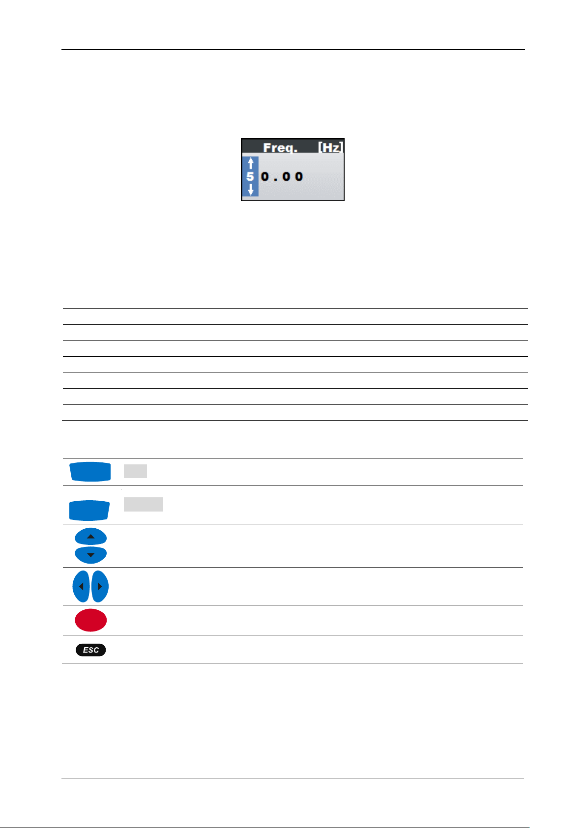
3.3.10 Frequency
By using left and right cursor, user can switch between predefined system
frequencies:
50 Hz
60 Hz
System frequency may be manipulated more accurate by using Edit menu. See section
3.9 Edit menu for more detailed description.
3.3.11 Event type
By using left and right cursor, user can switch between predefined system
events. List of available events:
Dip – voltage dip
17
Page 18

MI 2891 Power Simulator Operating the instrument
Swell – voltage swell
Interrupt – voltage interrupt
Inrush – inrush current
Signalling – signalling voltage event for remote control of network equipment
Transient – voltage transient
See section 3.10 Events for event setup and configuration.
3.3.12 Event occurrence
By using left and right cursor, user can change time interval of event
occurrence. Following options are available.
Keys only – single events will occur manually, by pressing shortcut keys.
10 s – selected event will occur once each 10 seconds.
Random – selected event will occur randomly in between 1 second and 20
second interval.
Manual – user selectable event occurrence interval. By pressing ENTER key,
additional dialog will be open, where user can set event occurrence interval
within 1 s … 60 s.
Figure 3.7: Manual set time delay dialog
3.3.13 Swap channels
By using left and right cursor, user can select following options to swap
channels:
Voltage [1 2 3 N] – status of voltage channel mapping. Press ENTER to change
it.
Current [1 2 3 N] – status of current channel mapping. Press ENTER to change it.
For example, voltage U1 can be sent to output terminal L3, instead of terminal L1
(normally used), and vice versa. In this way, simulator is used do simulates wrongly
connected Power Quality analyser. See next figure and section 3.11 Swap connection
terminals for details.
18
Page 19

MI 2891 Power Simulator Operating the instrument
N
Power Simulator
MI2891
Power Meter
MI2892
Swapping channels emulate
faulty wiring between
simulator and analyser (in
this example wire L1 and L3).
DIP
Short press
Enable single phase dip event.
Long press (2 s)
Enable single phase interrupt event.
Swell
Short press
Enable single phase swell event.
Long press (2 s)
Enable single phase inrush event.
Short press
Generates harmonics on voltage.
Long press (2 s)
Generates harmonics on current.
Short press
Changes between inductive/capacitive network
Figure 3.8: Swapping instrument channels
3.3.14 Factory reset
Factory reset set instrument settings to factory default settings. Note, that this will reset
all user defined parameters. After ENTER key is pressed, a confirmation is required in
order to perform the reset.
3.4 Keyboard shortcuts
Power Simulator has few keyboard shortcuts in order access common functions quickly.
Each shortcut key has two working regimes: short or two seconds long key press. See
table below for detailed description.
Table 3.5: Shortcut keys
19
Page 20

MI 2891 Power Simulator Operating the instrument
character
Long press (2 s)
Changes between load/generator network type.
F1
Figure 3.9: Voltage only waveform
Figure 3.10: Current only waveform
Figure 3.11: Voltage and current
waveform (single mode)
Figure 3.12: Voltage and current
waveform (dual mode)
U1, U2, U3, Un
U12, U23, U31
True effective value of phase voltage: U1, U2, U3, U
N
True effective value of phase to phase voltage: U12, U23, U31
I1, I2, I3, In
True effective value of current: I1, I2, I3, IN
F2
Selects which waveforms to show:
U I U,I U/I
Shows voltage waveform.
U I U,I U/I
Shows current waveform.
3.5 Scope screen
Voltage and current parameters can be observed in the scope screen. Currently
generating waveform can be viewed in graphical form (SCOPE). User can enter the
screens by pressing
key from Main menu. Various combinations of voltage and
current waveforms can be displayed on the instrument, as shown below.
Table 3.6: Instrument screen symbols and abbreviations
Table 3.7: Keys in Scope screen
20
Page 21

MI 2891 Power Simulator Operating the instrument
U I U,I U/I
Shows voltage and current waveform (single graph).
U I U,I U/I
Shows voltage and current waveform (dual graph).
F3
Selects between phase, neutral, all-phases and line view:
1 2 3 N Δ
Shows waveforms for phase L1.
1 2 3 N Δ
Shows waveforms for phase L2.
1 2 3 N Δ
Shows waveforms for phase L3.
1 2 3 N Δ
Shows waveforms for neutral channel.
1 2 3 N Δ
Shows all phase waveforms.
1 2 3 N Δ
Shows all phase-to-phase waveforms.
ENTER
Selects which waveform to zoom (only in U/I or U+I).
Sets vertical zoom.
Sets horizontal zoom.
Returns to the Main menu.
F2
3.6 Phase Diagram
Phase diagram graphically represents system frequency, fundamental voltages,
currents and phase angles of the simulated waveforms. This view is strongly
recommended for checking instrument settings before and during simulation, as most
issues arise from wrongly connected instrument (see Figure 5.1 for connecting Power
Simulator with Power Quality Analyser). Phase diagram screens display:
Graphical presentation of voltage and current phase vectors of the simulated
system,
Symmetrical components and unbalance of the simulated system.
3.6.1 Phase diagram
By entering PHASE DIAGRAM option,
screen is shown (see figure below).
key, from MAIN MENU, the following
Figure 3.13: Phase diagram screen
21
Page 22

MI 2891 Power Simulator Operating the instrument
f
Frequency.
U1, U2, U3
Fundamental voltages Ufund1, Ufund2, Ufund3 with relative phase
angle to Ufund1.
I1, I2, I3
Fundamental currents Ifund1, Ifund2, Ifund3 with relative phase angle
to Ufund1.
F1
EDIT
Enters signal parameters submenu screen. This option is
available only if Voltage or Current unbalance in Main menu is
set to Manual. See section 3.9 Edit menu for details.
F2
U I
I U
Selects voltage for scaling (with cursors).
Selects current for scaling (with cursors).
F4
UNBAL.
Switches to UNBALANCE DIAGRAM view.
Scales voltage or current phasors.
Returns to the Main menu.
F1
F3
Table 3.8: Instrument screen symbols and abbreviations
Table 3.9: Keys in Phase diagram screen
3.6.2 Unbalance diagram
Unbalance diagram represents current and voltage unbalance of the generating system.
Unbalance arises when RMS values or phase angles between consecutive phases are
not equal. Diagram is shown in figure below.
Both voltage and current unbalances can be set from Main menu by selecting either of
predefined “low” or “high” unbalance. It is also possible to use manual settings menu, to
set each phase separately through EDIT MENU, accessible through EDIT button -
key from Phase diagram / Unbalance diagram screens, or
Main menu.
key from
Figure 3.14: Unbalance diagram screen
22
Page 23

MI 2891 Power Simulator Operating the instrument
U0
I0
Zero sequence voltage component U
0
Zero sequence current component I
0
U+
I+
Positive sequence voltage component U
+
Positive sequence current component I
+
UI-
Negative sequence voltage component U
-
Negative sequence current component I
-
u-
i-
Negative sequence voltage ratio u
-
Negative sequence current ratio i-
u0
i0
Zero sequence voltage ratio u
0
Zero sequence current ratio i0
F1
EDIT
Enters signal parameters submenu screen. This option is
available only if Voltage or Current unbalance in Main menu is
set to Manual. See section 3.9 Edit menu for details..
F2
U I
I U
Shows voltage unbalance measurement and selects voltage
for scaling (with cursors).
Shows current unbalance measurement and selects current
for scaling (with cursors).
F4
METER
Switches to PHASE DIAGRAM view.
Scales voltage or current phasors.
Returns to the Main menu.
Table 3.10: Instrument screen symbols and abbreviations
Table 3.11: Keys in Unbalance diagram screen
3.7 Harmonics
Harmonics represent voltage and current signals as a sum of sinusoids of power
frequency and its integer multiples. Sinusoidal wave with frequency k-times higher than
fundamental (k is an integer) is called harmonic wave and is denoted with amplitude
and a phase shift (phase angle) to a fundamental frequency signal. Example of a signal
with added harmonics is shown on figure below.
Figure 3.15: 230V fundamental voltage signal with added 5% of 3rd, 5th and 7th harmonic
23
Page 24

MI 2891 Power Simulator Operating the instrument
F2
3.7.1 Harmonics settings screen
By entering either Voltage or Current harmonics option from MAIN MENU, harmonics
screen is shown (see figures below). In these screens, voltage or current harmonics are
shown. All values presented are in % of phase fundamental voltage / current).
Figure 3.16: Voltage harmonics settings screen
Figure 3.17: Current harmonics settings screen
If Manual option is selected at Voltage or Current harmonics setup, user can modify
settings for each of the specified, all up to 50th, voltage and/or current harmonics.
Currently selected parameter is coloured blue. A selection window, example in Figure
3.18, is opened after pressing ENTER key. Setting is made by using cursor keys,
confirmed as the window is closed (ENTER or ESC key) and enabled, when SET
key is pressed.
Figure 3.18: Set harmonic selection window
Description of symbols and abbreviations used in METER screens are shown in table
below.
24
Page 25

MI 2891 Power Simulator Operating the instrument
THD
Total voltage / current harmonic distortion THDU and THDI in absolute
values (V or A) or in % of fundamental voltage / current harmonic.
h1 … h50
n-th harmonic voltage Uhn or current Ihn component in absolute
values (V or A) or in % of fundamental voltage / current harmonic.
F1
RESET
Reset all harmonics to zero.
F2
SET
Refresh (activate) currently set manual harmonics.
F3
VIEW
Enters window to switch between absolute (V, A) and relative
(% of nominal) harmonics values.
F4
BAR
Switches to BAR view.
Shifts through harmonic components.
Shifts through channels, increase/decrease harmonic level.
Switches between absolute and relative harmonics values.
ENTER
Enters harmonic selection window.
Returns to the Main menu.
Closes harmonic selection window.
Closes window to switch between absolute and relative harmonics values.
Table 3.12: Instrument screen symbols and abbreviations
Table 3.13: Keys in Harmonics (METER) screens
3.7.2 Histogram (Bar)
Bar screen displays dual bar graphs. The upper bar graph shows voltage harmonics
and the lower bar graph shows current harmonics.
Figure 3.19: Harmonics histogram screen
25
Page 26

MI 2891 Power Simulator Operating the instrument
Ux h01 … h50
Voltage harmonic component in V
RMS
and in % of fundamental
voltage; [x: 1, 2, 3, n].
Ix h01 … h50
Current harmonic component in A
RMS
and in % of fundamental
current; [x: 1, 2, 3, n].
Ux THD
Total voltage harmonic distortion THDU in V and in % of fundamental
voltage; [x: 1, 2, 3, n].
Ix THD
Total current harmonic distortion THDI in A
RMS
and in % of
fundamental current; [x: 1, 2, 3, n].
F3
Selects between single phases and neutral channel
harmonics bars.
1 2 3 N
Shows harmonics components for phase L1.
1 2 3 N
Shows harmonics components for phase L2.
1 2 3 N
Shows harmonics components for phase L3.
1 2 3 N
Shows harmonics components for neutral channel.
F4
METER
Switches to METER view.
Scales displayed histogram by amplitude.
Scrolls cursor to select single harmonic bar.
ENTER
Toggles cursor between voltage and current histogram.
Returns to the Main menu.
Description of symbols and abbreviations used in BAR screens are shown in table
below.
Table 3.14: Instrument screen symbols and abbreviations
Table 3.15: Keys in Harmonics (BAR) screen
3.8 Flickers
Flicker is impression of unsteadiness of visual sensation induced by a light stimulus
whose luminance or spectral distribution fluctuates with time. Power simulator use
amplitude modulation according to the IEC 61000-4-15 standard, to provide flicker on
voltage outputs.
By enabling Flickers option from the MAIN MENU, flicker is added to the voltage
outputs. Flicker parameters depend on fundamental voltage of the system and selected
system frequency. Pst value may be set as desired in ranges 0.50 to 5.00 in 0.10 steps,
whereas CPM and ΔU/U values are defined according to IEC61000-4-15 standard,
table 5.
26
Page 27

MI 2891 Power Simulator Operating the instrument
Pst
Short term flicker perceptibility.
CPM
Voltage changes per minute.
ΔU/U
Voltage fluctuation in %.
F1
RESET
Reset flickers to default.
F2
SET
Refresh (activate) currently set flickers.
Scrolls between Pst and CPM parameters.
Scrolls cursor to select single phase.
ENTER
Enters parameter settings submenu.
Returns to the Main menu.
Closes parameter settings submenu.
F3
Figure 3.20: Flicker settings menu
Description of symbols and abbreviations used in FLICKERS screen is shown in table
below.
Table 3.16: Instrument screen symbols and abbreviations
Table 3.17: Keys in Flickers screen
3.9 Edit menu
The menu is accessed by pressing
menu is displaying and ability to modify settings for each phase and system frequency.
Currently selected parameter is coloured blue (see figure below). Note, that certain
system parameters (e.g. Flicker generator) depend on fundamental voltage setting,
rather than voltage parameters provided through edit menu.
key from Main menu. Main feature of this
27
Page 28

MI 2891 Power Simulator Operating the instrument
Figure 3.21: U,I: Parameters screen
User can move between parameters using cursor keys. By pressing ENTER key,
parameter value selection window is displayed. By pressing cursor keys, parameter
value is changed. Selection window can be closed by using either ESC or ENTER key.
At same time, set parameters are enabled. Separate voltage, current, phase angle can
be manipulated separately.
Voltage can be set in 0.01 V resolution within voltage range 0.00 V to 350.00 V by using
arrow keys.
Figure 3.22: Set voltage selection window
Current can be set in 0.1 A resolution within current range 100.0 A to 2000.0 A by using
arrow keys.
Figure 3.23: Set current selection window
Angle offset for both current and voltage phases can be set in 1° step.
Figure 3.24: Set phase selection window
System frequency can be set:
28
Page 29
MI 2891 Power Simulator Operating the instrument
L1, L2, L3, N
Phases.
Urms
Phase voltage.
Uphase
Voltage phase angle.
Irms
Phase current.
Iphase
Current phase angle.
Freq.
System frequency.
DPF
U-I Displacement power factor (cos φ)
F1
SET
Refresh (activate) currently set values.
F4
RESET
Resets all but frequency parameters to default settings.
Scrolls cursor between options.
Scrolls cursor to select single phase.
ENTER
Enters parameter value selection window.
Returns to the Main menu.
Exits from parameter value selection window.
when chosen, user can set frequency in 1 Hz step by using left/right arrow keys,
when chosen, user can enter selection menu by pressing ENTER key, then set
desired frequency in 0.01 Hz step within frequency range 45.00 Hz to 70.00 Hz
by using arrow keys.
Figure 3.25: Set frequency selection window
Settings can be reset to default values by using RESET option. This will discard all but
frequency changes made.
Table 3.18: Instrument screen symbols and abbreviations
Table 3.19: Keys in Edit menu screen
3.10 Events
This section describes event generator functionality, their corresponding screens and
manipulation. Six types of events can be generated: voltage dip, swell, interrupt, current
inrush, signalling and transient. For each of them user can set various parameters.
Additionally, some of them can occur on single or multiple phases.
29
Page 30

MI 2891 Power Simulator Operating the instrument
-400
-300
-200
-100
0
100
200
300
400
0 0.02 0.04 0.06 0.08 0.1 0.12 0.14 0.16 0.18 0.2
U [V]
T [s]
Dip
F4
SET
Refresh (activate) currently set dip.
Scrolls cursor between options.
3.10.1 Dip
Voltage Dip is sudden voltage reduction, followed by voltage recovery after a short time
interval, from a few periods of the sinusoidal wave of the voltage to a few seconds.
Figure 3.26: Dip event, 80 % U
Dip can be manually triggered with
, 4 periods long
Nom
shortcut key or can be periodically
repeated, according to EVENT OCCURRANCE setting in MAIN MENU. By entering the
Dip submenu, following options are available:
Level – using left and right cursor key, user can set dip level in range 10 % to 99
% of Unom.
Duration – using left and right cursor key, user can set dip duration in periods
from 1 period to 100 periods.
Phase type – user can switch between Single (L1) and Poly-phase event type.
New settings will apply when SET is pressed or when dip settings submenu is closed.
Figure 3.27: Dip settings submenu
Table 3.20: Keys in dip settings submenu
30
Page 31

MI 2891 Power Simulator Operating the instrument
Modifies parameter.
ENTER
Enters parameter value selection window.
Returns to the Main menu.
Exits from parameter value selection window.
-400
-300
-200
-100
0
100
200
300
400
0.00 0.05 0.10 0.15 0.20
U [V]
T [s]
Swell
3.10.2 Swell
Swell is sudden voltage increase, followed by voltage recovery after a short time
interval, from a few periods to a few seconds.
Figure 3.28: 5 periods long swell, 110 % U
Swell can be manually triggered with
repeated, according to EVENT OCCURRANCE setting in MAIN MENU. By entering the
Swell submenu, following options are available:
Level – using left and right cursor key, user can set swell level in range 101 % to
150 % of Unom.
Duration – using left and right cursor key, user can set swell duration in periods
from 1 period to 100 periods.
Phase type – user can switch between Single (L1) and Poly-phase event type.
New settings will apply when SET is pressed or when swell settings submenu is closed.
Figure 3.29: Swell settings menu
31
Nom
shortcut key or can be periodically
Page 32

MI 2891 Power Simulator Operating the instrument
F4
SET
Refresh (activate) currently set swell.
Scrolls cursor between options.
Modifies parameter.
ENTER
Enters parameter value selection window.
Returns to the Main menu.
Exits from parameter value selection window.
-400
-300
-200
-100
0
100
200
300
400
0.00 0.02 0.04 0.06 0.08 0.10 0.12 0.14 0.16 0.18 0.20
U [V]
T [s]
Dip
Table 3.21: Keys in swell settings submenu
3.10.3 Interrupt
Interruption is condition where output voltage at the output terminals drops to selected
interrupt level, usually too few percent of nominal voltage.
Figure 3.30: Interrupt 0 % U
Interrupt can be manually triggered with
be periodically repeated, according to EVENT OCCURRANCE setting. By entering the
Interrupt submenu, following options are available:
Level – using left and right cursor key, user can set interrupt level in range 0 % to
10 % of Unom.
Duration – using left and right cursor key, user can set interrupt duration in
periods from 1 period to 100 periods.
Phase type – user can switch between Single(L1) and Poly-phase event type.
New settings will apply when SET is pressed or when Interrupt settings submenu is
closed.
32
, 5 periods long
Nom
shortcut key (long press – 2 s) or can
Page 33

MI 2891 Power Simulator Operating the instrument
F4
SET
Refresh (activate) currently set interrupt.
Scrolls cursor between options
Modifies parameter.
ENTER
Enters parameter value selection window.
Returns to the Main menu.
Exits from parameter value selection window.
2
1
))log(1(
2
1
k
I
inrush
-3
-2
-1
0
1
2
3
0.00 0.05 0.10 0.15 0.20 0.25 0.30 0.35 0.40
U [V]
T [s]
Figure 3.31: Interrupt settings submenu
Table 3.22: Keys in interrupt settings submenu
3.10.4 Inrush
Inrush current is transient current associated with energizing of transformers, cables,
reactors, etc. Usually high current is drawn, which produce voltage dip consequently.
Inrush current waveshape is generated by applying logarithmic formula:
-
Figure 3.32: Inrush on voltage
to particular part of the current waveform,
33
Page 34

MI 2891 Power Simulator Operating the instrument
)1log( kUU
inrush
-400
-300
-200
-100
0
100
200
300
400
0.00 0.05 0.10 0.15 0.20 0.25 0.30 0.35 0.40
U [V]
T [s]
Swell
F4
SET
Refresh (activate) currently set inrush.
Modifies parameter.
Returns to the Main menu.
-
to particular part of the voltage waveform,
Figure 3.33: Inrush on current
In practice, inrush current event will generate approximately 50% overshoot of
Fundamental current and it will last about 10 seconds. Inrush event can be manually
triggered with
shortcut key (long press – 2 s) or can be periodically repeated,
according to EVENT OCCURRANCE setting in MAIN MENU. By entering the submenu,
next options are available:
Phase type – user can switch between Single(L1) and Poly-phase event type.
New settings will apply when SET is pressed or when Inrush settings submenu is
closed.
Figure 3.34: Inrush settings submenu
Table 3.23: Keys in inrush settings submenu
34
Page 35

MI 2891 Power Simulator Operating the instrument
-400
-300
-200
-100
0
100
200
300
400
0.00 0.01 0.02 0.03 0.04 0.05 0.06 0.07 0.08 0.09 0.10
U [V]
T [s]
3.10.5 Signalling
Signalling voltage is voltage superimposed to the output voltage for the purpose of
transmission of information in the public supply network and to network users' premises.
Power simulator provides “ripple control signal”: superimposed sinusoidal voltage
signals in the frequency range 70 Hz to 3 000 Hz.
Figure 3.35: Generated signalling, 10 % U
, signalling frequency 316.0 Hz
Nom
Signalling event is periodically repeated, according to EVENT OCCURRANCE setting in
MAIN MENU. By entering the submenu, next options are available:
Level – using left and right cursor key, user is given the option to set amplitude,
based on % of currently generating signal. Level may be set in range 0 % to 10
% of Unom.
Duration – using left and right cursor key, user can set signalling duration in
seconds, from 1 s to 100 s.
Phase type – using left and right cursor key, user can switch between Single(L1)
and Poly-phase event type.
Frequency – using left and right cursor key, user can set signalling frequency in
0.1 Hz increments in range from 50.0 Hz to 3000.0 Hz.
New settings will apply when SET is pressed or when Signalling settings submenu is
closed.
Figure 3.36: Signalling settings submenu
35
Page 36

MI 2891 Power Simulator Operating the instrument
F4
SET
Refresh (activate) currently set signalling.
Scrolls cursor between options
Modifies parameter.
ENTER
Enters parameter value selection window.
Returns to the Main menu.
Exits from parameter value selection window.
Table 3.24: Keys in signalling settings submenu
3.10.6 Transient
Transient is overvoltage with a duration of a few milliseconds. Power Simulator
generates oscillatory damped transient on U1 channel, as shown on figure below.
Transient event have overshoot approximately 70% of nominal voltage high and last
about 8% of period duration (period is defined with Frequency parameter), as shown on
figure below.
Figure 3.37: Generated transient sample, captured by MI 2892 Power Master
Transient event is periodically repeated, according to EVENT OCCURRANCE setting in
MAIN MENU. By entering the submenu, next options are available:
Phase type – user can switch between Single(L1) and Poly-phase event type.
36
Page 37

MI 2891 Power Simulator Operating the instrument
F4
SET
Refresh (activate) currently set transient.
Modifies parameter.
Returns to the Main menu.
New settings will apply when SET is pressed or when Transient settings submenu is
closed.
Figure 3.38: Transient settings submenu
Table 3.25: Keys in transient settings submenu
3.11 Swap connection terminals
In order to represent problems with wrongly connected instrument, and to see how
difficult is to spot such problem, Power Simulator has additional functionality for
swapping voltage or current channels. Both voltage and current channels can be
swapped. By entering a submenu through “Voltage” or “Current” option user can
manually swap two output channels (voltage or current). This simulates wrong
clamps/voltage lead connection, without physically swapping cables. New settings will
apply when SET is pressed or when Swap connections submenu is closed.
Figure 3.39: Change sequence submenu screen
37
Page 38

MI 2891 Power Simulator General Setup
F1
SET
Activates swap of Voltage / Current channels.
F4
RESET
Set Voltage / Current channels to normal connection.
ENTER
Enters parameter value selection window.
Modifies parameter (in selection window).
Returns to the Main menu.
Exits from parameter value selection window.
Instrument info
Information about the instrument.
Colour Model
Select colours for displaying phase measurements.
Select submenu.
ENTER
Enters submenu.
Returns to the Main menu.
Table 3.26: Keys in Swap connections screen
4 General Setup
General setup menu can be accessed by using SETTINGS key from Main
menu. From the “GENERAL SETUP” menu, colour model for displaying phase
measurements can be reviewed, configured and saved. It is also possible to view
instrument information.
Figure 4.1: General setup menu
Table 4.1: Description of General setup options
Table 4.2: Keys in General setup menu
38
Page 39

MI 2891 Power Simulator General Setup
Returns to the General setup menu.
F1
EDIT
Opens edit colour screen (only available in custom model).
4.1.1 Instrument info
Basic information concerning the instrument (company, serial number, firmware and
hardware version) can be viewed in this menu.
Figure 4.2: Instrument info screen
Table 4.3: Keys in Instrument info screen
4.1.2 Colour model
In COLOUR MODEL menu, user can change colour representation of phase voltages
and currents, according to his needs. There are some predefined colour schemes (EU,
USA, etc.) and a custom mode where user can set up its own colour model.
Figure 4.3: Colour representation of phase voltages
Table 4.4: Keys in Colour model screens
39
Page 40

MI 2891 Power Simulator General Setup
Keys in Edit colour screen:
F1
L1 L2 L3 N
Shows selected colour for phase L1.
L1 L2 L3 N
Shows selected colour for phase L2.
L1 L2 L3 N
Shows selected colour for phase L3.
L1 L2 L3 N
Shows selected colour for neutral
channel N.
Selects colour.
ENTER
Returns to the “COLOUR MODEL” screen.
Selects Colour scheme.
ENTER
Returns to the General setup menu.
40
Page 41
MI 2891 Power Simulator Instrument Connection
N
N
Power Simulator
MI 2891
Power Master
MI 2892
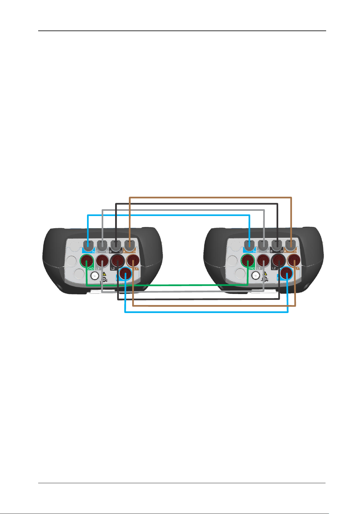
5 Instrument Connection
5.1 Wiring Power Simulator MI2981 to Power Master 2982
This section describes how to connect Power Simulator MI 2891 to Power Master MI
2892 using enclosed test leads.
All outputs from Power Simulator MI 2891 should be connected to adequate inputs of
Power Master MI 2892.
Current leads should be connected as shown in Figure 5.1. I1 current output from
Power Simulator should be connected to I1 input of Power Master.
Voltage leads should be connected as shown in Figure 5.1. L1 voltage output from
Power Simulator should be connected to L1 input of Power Master.
N output from Power Simulator should be connected to N input of Power Master.
Analogy applies to all other input/output combinations.
Figure 5.1: Recommended lead connection
After connecting all input/output ports, Power Simulator and Power Master may be
turned on and are ready for use.
5.2 Simulation campaign
In following section recommended signal simulation is described. Refer to Power Master
MI 2892 Instruction manual for handling measuring site. We recommend to strictly
follow the guidelines in order to avoid common problems, measurement and simulation
mistakes. Figure below shortly summarizes recommended simulation practice. Each
step is then shortly described in details.
41
Page 42

MI 2891 Power Simulator Instrument Connection
Power Simulator
MI 2891
Power Meter MI 2892
Instrument
preparation
Plug in voltage and current
leads
Turn on instruments
Step 1:
Instrument setup
Make sure, that you always plug in
leads on Power Meter MI 2892 first.
Make sure, that Power Simulator is
turned off before plugging in any
wiring.
Set voltage level
Set clamps current
Set frequency
Set harmonics/events/flickers
Step 2:
Set connection properties
Set nominal voltage
Set phase curr. clamps
Set neutral curr. Clamps
Set connection type to 4W
Set system frequency
Step 3:
Measurement setup
Simulate desired
waveforms
Step 4:
Measurement campaing
Check Power Master MI 2892
Instruction manual for detailed
measurement campaign
instructions
Stop simulation
Turn off Power Simulator
Disconnect test leads
Step 4:
Stop simulation
Step 1: Instrument setup
Preparation of Power Simulator MI 2891 and Power Master MI 2892 includes the
following steps:
Visually check both instruments and accessories.
Make sure, that Power Simulator MI 2891 is turned off.
Connect test leads as described in section 5.1 Wiring Power Simulator MI2981 to
Figure 5.2: Recommended simulation practice
Power Master 2982. Always plug in leads on Power Master first and only then on
Power Simulator.
Warnings!
Don’t use visually damaged equipment!
Always use batteries that are in good condition and fully charged.
42
Page 43

MI 2891 Power Simulator Instrument Connection
Step 2: Set connection properties
Simulator setup adjustment is performed after we find out details regarding wanted
simulated waveform:
set desired fundamental voltage level,
set clamps current,
set system frequency,
set harmonics/events/flickers/unbalances… as desired.
Step 3: Measurement setup
On Power Master MI 2892, enter Connection setup submenu. Following parameters
have to be set in order to provide trustworthy measurements:
Nominal voltage L-N: nominal voltage represents goal voltage of our simulated
environment. Generally, this means setting it to same value, as fundamental
voltage on simulator site.
Phase current clamps: in order to provide correct current measurements, A 1033
clamps with proper A/V ratio should be chosen, as seen in simulator’s main
screen.
Neutral current clamps: in order to provide correct current measurements, A
1033 clamps with proper A/V ratio should be chosen, as seen in simulator’s main
screen.
Connection type: 4W
System frequency:
o 50Hz if <55Hz setting on simulator
o 60Hz otherwise
Connection check will show, if everything was set correctly. In case of wrong
connection, repeat step 3. If that didn’t help eliminating the problem, re-check
wiring between Power Simulator and Power Master.
Set up alarms/events to fit your needs.
Set up recorder.
Step 4: Measurement campaign
Perform simulation and measurement scenarios. For detailed instructions regarding
measurements, check Power Master 2892 Instruction manual.
Step 5: Stop simulation
Safe removal of test leads is important for user’s maximum safety.
Warning!
Always turn off Power Simulator first, and only then disconnect test leads.
43
Page 44
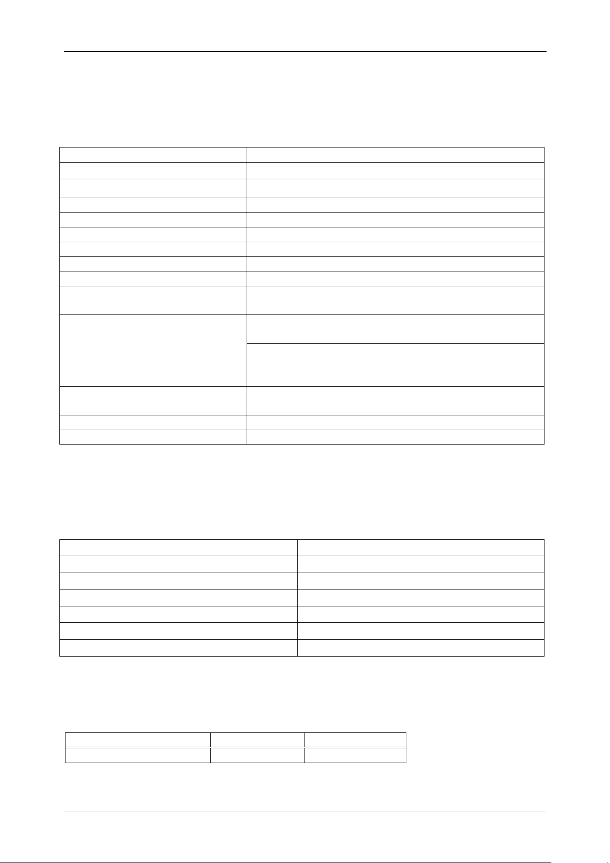
MI 2891 Power Simulator Technical specifications
Working temperature range:
-20 C … 40 C
Storage temperature range:
-40 C … 70 C
Max. humidity:
95 % RH (0 C … 40 C), non-condensing
Pollution degree:
2
Protection classification:
Reinforced insulation
Measuring category:
CAT I / 300 V
Protection degree:
IP 30
Dimensions:
23 cm x 14cm x 8 cm
Weight (with batteries):
1.36 kg
Display:
Colour 4.3’’ (10.9 cm) TFT liquid crystal display
(LCD) with backlight, 480 x 272 dots.
Batteries:
6 x 1.2 V NiMH rechargeable batteries
type HR 6 (AA)
Battery operation up to 30 mins*
Given accuracy is guaranteed only when battery
charger is present.
External DC supply - charger:
100-240 V~, 50-60 Hz, 1.5 A~, CAT II / 300 V
12 V DC, min 3 A
Maximum supply consumption:
12 V / 1.5 A ( while charging batteries )
Battery charging time:
3 hours*
Max. output voltage (Phase – Neutral):
370 V
RMS
Max. output voltage (Phase – Phase):
740 V
RMS
Minimal voltage output load impedance:
200 kΩ
Minimal current output load resistance
10 kΩ
D/A converter
16 bit 8 channels, simultaneous sampling
Sampling frequency:
720 x System Frequency (36 kHz@50 Hz)
Reference temperature
23 °C ± 2 °C
Output voltage
Resolution
Accuracy
50 … 300 V
10 V
± 0.1 %
6 Technical specifications
6.1 General specifications
* The charging time and the operating hours are given for batteries with a nominal
capacity of 2000 mAh.
6.2 Signal generator
6.2.1 General description
6.2.2 Voltages
Fundamental RMS voltage output: U1Rms, U2Rms, U3Rms, UNRms, AC+DC
44
Page 45

MI 2891 Power Simulator Technical specifications
Event voltage
Resolution
Accuracy
0 … 350 V
1 % of fundamental output voltage
± 2 %
Range
Output voltage
Overall current accuracy
A 1033 (100 A … 1000 A)
100 mV … 1 V
± 0.1 %
Frequency range
Resolution
Accuracy
45 Hz … 70 Hz
1 Hz
± 10 mHz
Flicker type
Flicker range
Resolution
Accuracy
Pst
0.5 … 5.0
0.1
± 1 %
Harmonics range
Resolution
Accuracy
UhN 1 % … 100 % of fundamental output voltage
1 % ± 5 % of UhN
Harmonics range
Resolution
Accuracy
IhN 1 % … 100 % of fundamental current
1 % ± 5 % of IhN
Unbalance range
Resolution
Accuracy
u-
0.5 % … 5.0 %
0.1 %
± 0.15 %
± 0.15 %
u0
i-
0.0 % … 20 %
0.1 %
± 1 %
± 1 %
i0
Operating range
Accuracy
Event RMS voltage output: U1Rms, U2Rms, U3Rms, UNRms, AC+DC
6.2.3 Current
Fundamental RMS current I1Rms, I2Rms, I3Rms, INRms, AC+DC.
6.2.4 Frequency
6.2.5 Flickers
6.2.6 Voltage harmonics
UhN: generated harmonic voltage
: harmonic component 2nd … 50
N
th
6.2.7 Current harmonics and THD
IhN: measured harmonic current
: harmonic component 2th … 50
N
th
6.2.8 Unbalance
6.2.9 Time and duration uncertainty
Real time clock (RTC) temperature uncertainty
45
Page 46

MI 2891 Power Simulator Technical specifications
-20 C … 70 C
± 3.5 ppm
0.3 s/day
0 C … 40 C
± 2.0 ppm
0.17 s/day
Measuring Range
Resolution
Error
Event
Duration
1 s … 60 s
1 s
1 cycle
Event duration uncertainty
46
Page 47
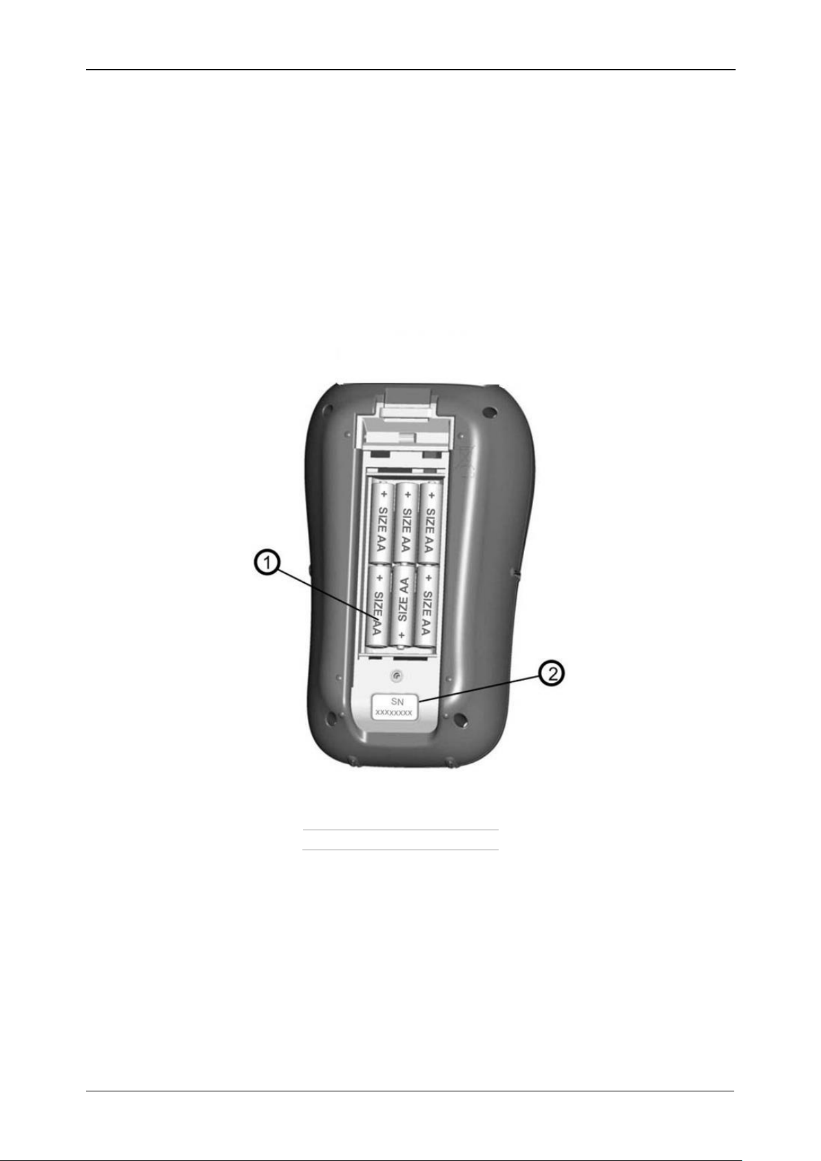
MI 2891 Power Simulator Maintenance
1
Battery cells
2
Serial number label
7 Maintenance
7.1 Inserting batteries into the instrument
1. Make sure that the power supply adapter/charger and measurement leads
are disconnected and the instrument is switched off before opening battery
compartment cover (see Figure 2.4).
2. Insert batteries as shown in figure below (insert batteries correctly, otherwise
the instrument will not operate and the batteries could be discharged or
damaged).
3. Turn the instrument upside down (see figure below) and put the cover on the
Figure 7.1: Battery compartment
batteries.
47
Page 48

MI 2891 Power Simulator Maintenance
Figure 7.2: Closing the battery compartment cover
4. Screw the cover on the instrument.
Warnings!
Hazardous voltages exist inside the instrument. Disconnect all test leads,
remove the power supply cable and turn off the instrument before
removing battery compartment cover.
Use only power supply adapter/charger delivered from manufacturer or
distributor of the equipment to avoid possible fire or electric shock.
Do not use standard batteries while power supply adapter/charger is
connected, otherwise they may explode!
Do not mix batteries of different types, brands, ages, or charge levels.
When charging batteries for the first time, make sure to charge batteries for
at least 24 hours before switching on the instrument.
Notes:
Rechargeable NiMH batteries, type HR 6 (size AA), are recommended. The
charging time and the operating hours are given for batteries with a nominal
capacity of 2000 mAh.
If the instrument is not going to be used for a long period of time remove all
batteries from the battery compartment. The enclosed batteries can supply the
instrument for approx. 30 minutes.
7.2 Batteries
Instrument contains rechargeable NiMH batteries. These batteries should only be
replaced with the same type as defined on the battery placement label or in this manual.
If it is necessary to replace batteries, all six have to be replaced. Ensure that the
batteries are inserted with the correct polarity; incorrect polarity can damage the
batteries and/or the instrument.
Precautions on charging new batteries or batteries unused for a longer period
Unpredictable chemical processes can occur during charging new batteries or batteries
that were unused for a longer period of time (more than 3 months). NiMH and NiCd
48
Page 49

MI 2891 Power Simulator Maintenance
batteries are affected to a various degree (sometimes called as memory effect). As a
result the instrument operation time can be significantly reduced at the initial
charging/discharging cycles.
Therefore it is recommended:
To completely charge the batteries.
To completely discharge the batteries (can be performed with normal working
with the instrument).
Repeating the charge/discharge cycle for at least two times (four cycles are
recommended).
When using external intelligent battery chargers one complete discharging /charging
cycle is performed automatically.
After performing this procedure a normal battery capacity is restored. The operation
time of the instrument now meets the data in the technical specifications.
Notes:
The charger in the instrument is a pack cell charger. This means that the batteries are
connected in series during the charging so all batteries have to be in similar state
(similarly charged, same type and age).
Even one deteriorated battery (or just of another type) can cause an improper charging
of the entire battery pack (heating of the battery pack, significantly decreased operation
time).
If no improvement is achieved after performing several charging/discharging cycles the
state of individual batteries should be determined (by comparing battery voltages,
checking them in a cell charger etc). It is very likely that only some of the batteries are
deteriorated.
The effects described above should not be mixed with normal battery capacity decrease
over time. All charging batteries lose some of their capacity when repeatedly
charged/discharged. The actual decrease of capacity versus number of charging cycles
depends on battery type and is provided in the technical specification of batteries
provided by battery manufacturer.
7.3 Firmware upgrade
Metrel as manufacturer is constantly adding new features and enhance existing. In
order to get most of your instrument, we recommend periodic check for software and
firmware updates. In this section firmware upgrade process is described.
7.3.1 Requirements
Firmware upgrade process has following requirements:
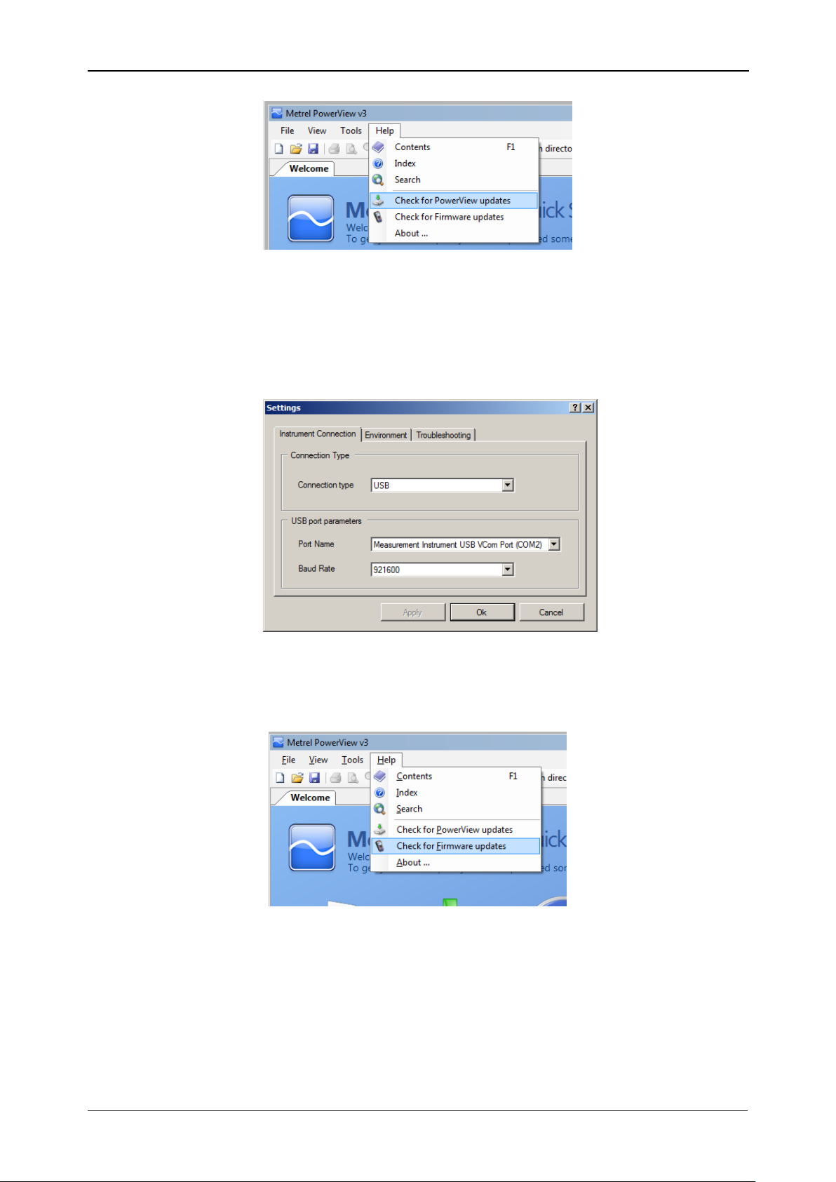
- PC computer with installed latest version of PowerView software. If your
PowerView is out of date, please update it, by clicking on “Check for
PowerView updates” in Help menu, and follow the instructions.
- USB cable
49
Page 50
MI 2891 Power Simulator Maintenance
Figure 7.3: PowerView update function
7.3.2 Upgrade procedure
1. Connect PC and instrument with USB cable
2. Establish USB communication between them. In PowerView, go to
ToolsOptions menu and set USB connection as shown on figure below.
Figure 7.4: Selecting USB communication
3. Click on Help Check for Firmware updates.
Figure 7.5: Check for Firmware menu
4. Version checker window will appear on the screen. Click on Start button.
50
Page 51

MI 2891 Power Simulator Maintenance
Figure 7.6: Version checker window
5. If your instrument have older FW, PowerView will notify you that new version of
FW is available. Click on Yes to proceed.
Figure 7.7: New firmware is available for download
6. After update is downloaded, FlashMe application will be launched. This
application will actually upgrade instrument FW. Click on RUN to proceed.
Figure 7.8: FlashMe firmware upgrade software starting screen
51
Page 52

MI 2891 Power Simulator Maintenance
7. FlashMe will automatically detect Power Master instrument, which can be seen in
COM port selection menu. In some rare cases user should point FlashMe
manually to COM port where instrument is connected. Click then on Continue to
proceed.
Figure 7.9: FlashMe configuration screen
8. Instrument upgrade process should begin. Please wait until all steps are finished.
Note that this step should not be interrupted; as instrument will not work properly.
If upgrade process goes wrong, please contact your distributor or Metrel directly.
We will help you to resolve issue and recover instrument.
52
Page 53

MI 2891 Power Simulator Maintenance
Figure 7.10: FlashMe programming screen
7.4 Power supply considerations
When using the original power supply adapter/charger the instrument is fully operational
immediately after switching it on. The batteries are charged at the same time, nominal
charging time is 3.5 hours.
The batteries are charged whenever the power supply adapter/charger is connected to
the instrument. Inbuilt protection circuit controls the charging procedure and assure
maximal battery lifetime. Batteries will be charged only if their temperature is less than
40 0C.
If the instrument is left without batteries and charger for more than 2 minutes, time and
date settings are reset.
Warnings!
Use only charger supplied by manufacturer.
Disconnect power supply adapter if you use standard (non-rechargeable)
batteries.
7.5 Cleaning
To clean the surface of the instrument use a soft cloth slightly moistened with soapy
water or alcohol. Then leave the instrument to dry totally before use.
Warnings!
53
Page 54

MI 2891 Power Simulator Maintenance
METREL d.d.
Ljubljanska 77,
SI-1354 Horjul,
Slovenia
Tel: +(386) 1 75 58 200
Fax: +(386) 1 75 49 095
Email: metrel@metrel.si
http://www.metrel.si
Do not use liquids based on petrol or hydrocarbons!
Do not spill cleaning liquid over the instrument!
7.6 Periodic calibration
To ensure correct measurement, it is essential that the instrument is regularly
calibrated. If used continuously on a daily basis, a six-month calibration period is
recommended, otherwise annual calibration is sufficient.
7.7 Service
For repairs under or out of warranty please contact your distributor for further
information.
7.8 Troubleshooting
If ESC button is pressed while switching on the instrument, the instrument will not start.
Batteries have to be removed and inserted back. After that the instrument will start
normally.
Manufacturer address:
54
 Loading...