

Page 1
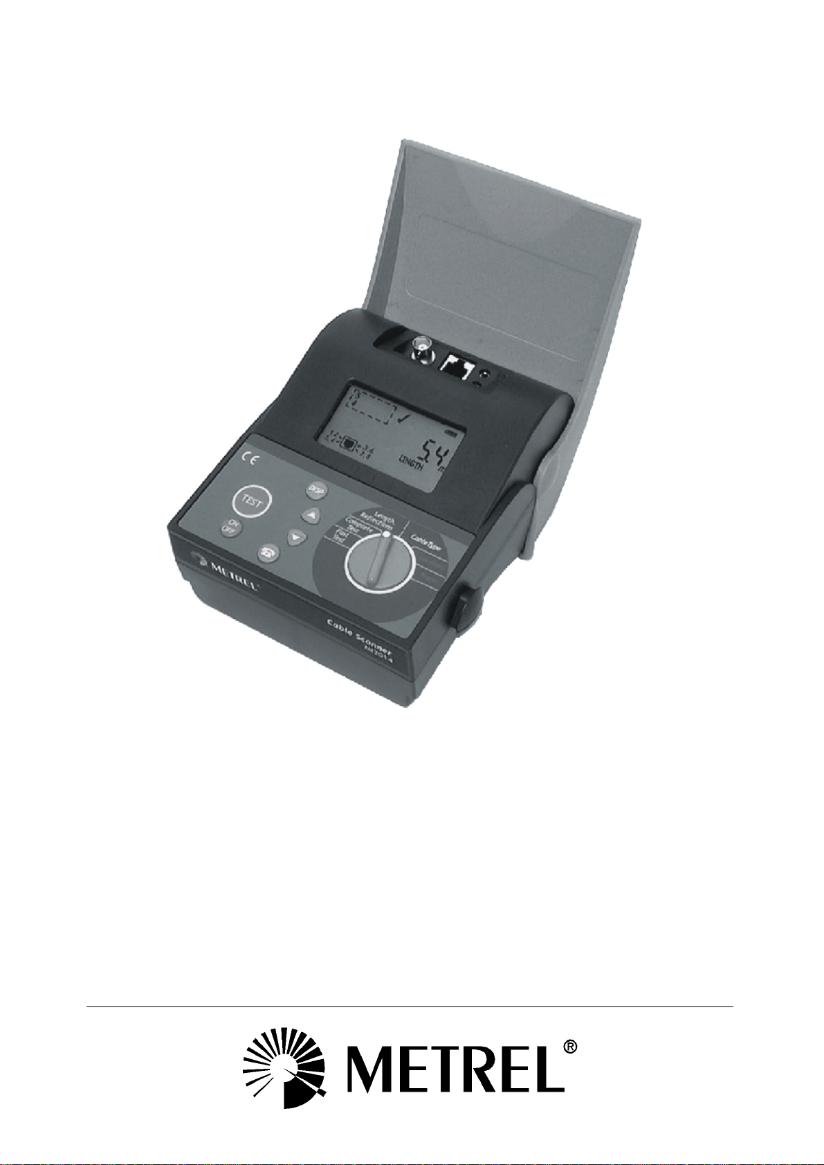
Cable Scanner
MI 2014
Instruction Manual
Code No.:20 750 429
Page 2

Distributor:
Manufacturer:
METREL d.d.
Ljubljanska cesta 77
1354 Horjul
Slovenia
web site: http://www.metrel.si
e-mail: metrel@metrel.si
Mark on your equipment certifies that this equipment meets the requirements of the
EU (European Union) concerning safety and interference causing equipment
regulations
© 2003 METREL
No part of this publication may be reproduced or utilized in any form or by any means
without permission in writing from METREL.
2
Page 3

MI 2014 Cable Scanner Table of contents
3
1. Cable Scanner MI 2014.............................................................................................4
Section I General information....................................................................................5
2. Safety and operational precautions........................................................................5
2.1 Warnings...............................................................................................................5
2.2 Battery replacement..............................................................................................5
2.3 Service and recalibration......................................................................................5
2.4 Maintainance and cleaning...................................................................................6
3. Cable scanner description.......................................................................................7
3.1 Front panel............................................................................................................7
3.2 Connector panels................................................................................................10
3.3 Bottom................................................................................................................10
4. Standard remote units description........................................................................11
5. Talk remote unit description..................................................................................11
Section II Specifications...........................................................................................12
6. Standard set............................................................................................................12
7. Optional accessories..............................................................................................12
8 Technical specifications..........................................................................................13
8.1 Fast Test.............................................................................................................13
8.2 Complete Test (with Remote units).....................................................................13
8.3 Length & Reflections...........................................................................................13
8.4 Locators..............................................................................................................14
8.5 Tracer.................................................................................................................14
9. General specifications............................................................................................15
9.1 General Data......................................................................................................15
9.2 Output connector, patch cable wiring: T568B.....................................................15
Section III Cable Scanner operation........................................................................16
10. Fast test.................................................................................................................16
11. Complete test........................................................................................................18
12. Length and reflections..........................................................................................20
12.1 Cable Length Calibrations.................................................................................24
13 Locators – Identification of cables.......................................................................26
14. Tracer – Tracing of cables and wires..................................................................27
15. Talk & Trace function............................................................................................28
15.1 Establishing a voice communication.................................................................28
15.2 Breaking off the connection..............................................................................29
15.3 Locating cables.................................................................................................29
15.4 Talk Remote Unit operation..............................................................................29
16. Cable type..............................................................................................................30
17. Reinitialisation (setting default values / length unit )........................................31
Page 4
MI 2014 Cable Scanner Cable Scanner MI 2014
4
1. Cable Scanner MI 2014
The Cable Scanner Tester is a portable handheld battery powered instrument intended
for testing LAN installations and cables.
Main features
• Fast Cable Test : most of connectivity tests can be performed by one operater
• Complete Cable Test (with Remote Unit): performs complete cable
connectivity test
• Cable identification (with Remote Unit or Locators)
• Cable length up to 300m, calibration facilities for accurate length measuring
• Amplitude and location of reflections are provided by an in built Time Domain
Reflectometer.
• Tone generator for tracing hidden cable paths and wire determination
• Talk function for communication over the cable link (with optional Talk Remote
unit)
• Supports coax and twisted pairs cables
The instrument is supplied with all accessories necessary for carrying out the tests.
The manual is divided into three sections, each covering a particular aspect of the
operation.
Section I General information
Section II Specifications
Section III Cable Scanner operation
Page 5

MI 2014 Cable Scanner Section I General information
5
Section I General information
2. Safety and operational precautions
2.1 Warnings
Ø Never connect the test equipment to an active network.
Ø Service is allowed to be carried out only by an authorised person!
Ø Use only standard or optional test accessories supplied by Metrel!
Ø Use only connector types equivalent to those built in to avoid damage to the
instrument components.
Ø If the test equipment is used in a manner not specified in this Users Manual,
the protection provided by the equipment may be impaired!
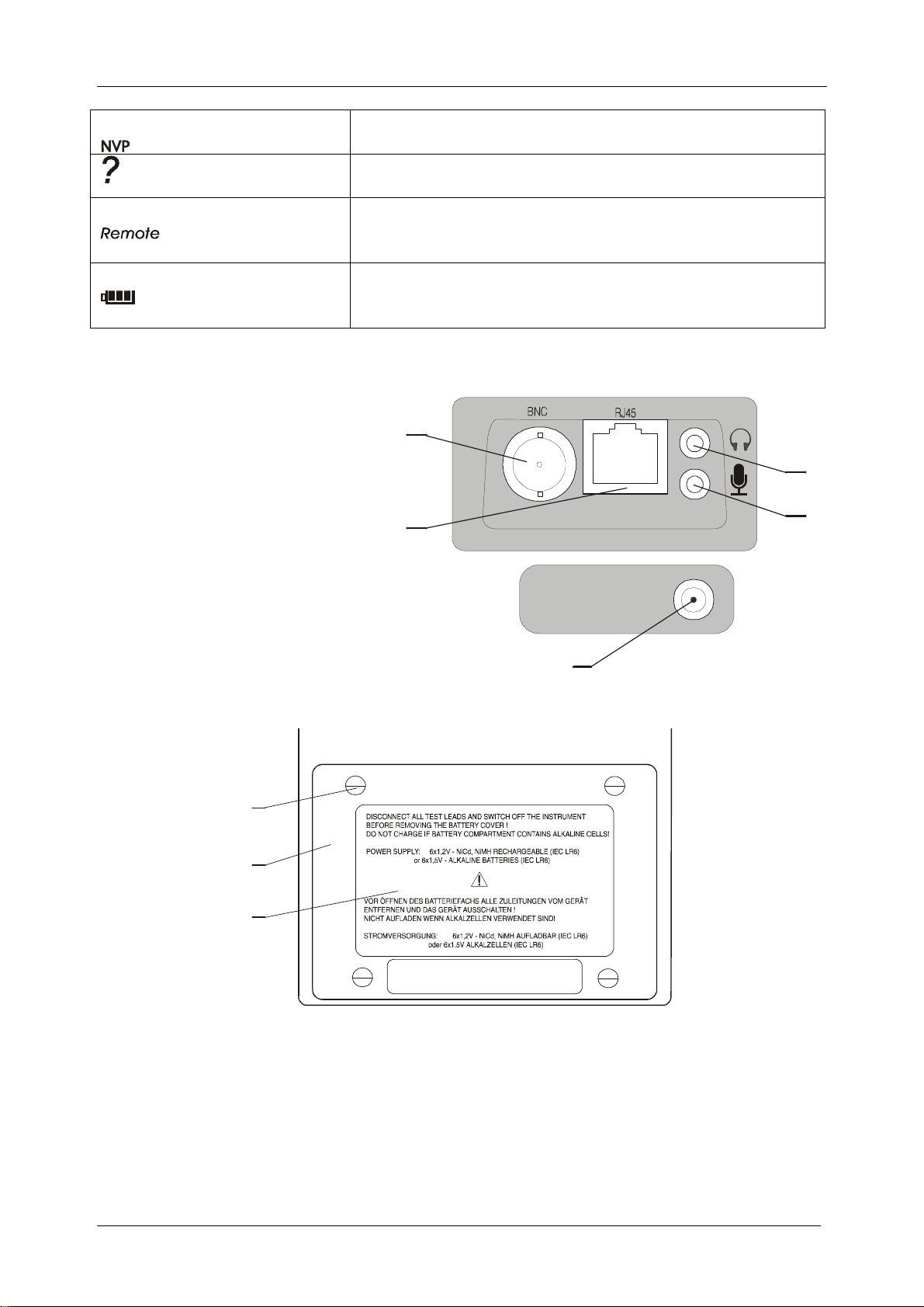
2.2 Battery replacement
Note
• Insert cells correctly, otherwise the instrument will not operate and the batteries
could be discharged.
• If the instrument is not to be used for a long period of time, remove all batteries from
the battery compartment.
• Battery compartment is protected with a fuse to prevent abnormal use of battery.
• External charger is not intended for supplying the instrument without batteries.
Warnings
Ø Do not charge alkaline batteries.
Ø Use only chargers delivered from Metrel or distributor of the test equipment to
avoid possible fire or electric shock.
Ø In case of blown fuse consult your distributor.
2.3 Service and recalibration
It is essential that test instrument is regularly calibrated in order technical specification
listed in this Instruction Manual to be guaranted. We recommend the calibration to be
carried out once per 2 years.
Metrel encloses to every new instrument an original calibration certificate.
For recalibration and repairs under or out of warranty time please contact your
distributor for further information.
Name and address of manufacturer:
METREL d.d.
Ljubljanska 77
SI-1354 Horjul
Tel.: +386 1 755 82 00
Fax.: +386 1 754 92 26
http://www.metrel.si;
E-mail:metrel@metrel.si
Page 6

MI 2014 Cable Scanner Section I General information
6
2.4 Maintainance and cleaning
Use a soft cloth, slightly moistened with soapy water, or cleaning alcohol, to clean the
surface of the instrument. Leave the instrument to dry completely before using it.
Page 7
MI 2014 Cable Scanner Section I General information
7
FUNCTION SWITCH
3. Cable scanner description
3.1 Front panel
LCD
KEYPAD
Page 8
MI 2014 Cable Scanner Section I General information
8
Front panel layout
Function switch selects one of six fuctional/operating menus:
Functional Menu Description
FAST TEST
COMPLETE TEST
LENGTH&
REFLECTIONS
CABLE TYPE Selectable 7 different cable types and wiring standards
LOCATORS Identification of up to 26 cables
TRACER Tracing of cables and wires (with optional Tracer)
Keypad
, ………… Selecting cable type, viewing subresults, calibration parameters
………………
Fast connectivity and TDR test (no Remote unit needed):
- determines cable length or termination
- finds cause and location of most frequently cable and
connectivity faults
Complete connectivity and TDR test (with Remote unit):
- determines cable length
- finds cause and location of all possible cable and connectivity
faults
- cable identification
Complete TDR cable check, calibration facilities
- finds cable length and termination
- location and amplitude of cable reflections.
- calibration facilities (on base of known NVP or cable length)
for accurate length measurements
Selecting calibration type, viewing subresults
……………….To turn on or off the instrument (Auto off after 10 minutes)
……………….Talk&Trace interface for talking over cable/ locating the Talk Remote
Unit
……… ……Starts test procedures, confirmation of selected items
Display
Page 9
MI 2014 Cable Scanner Section I General information
9
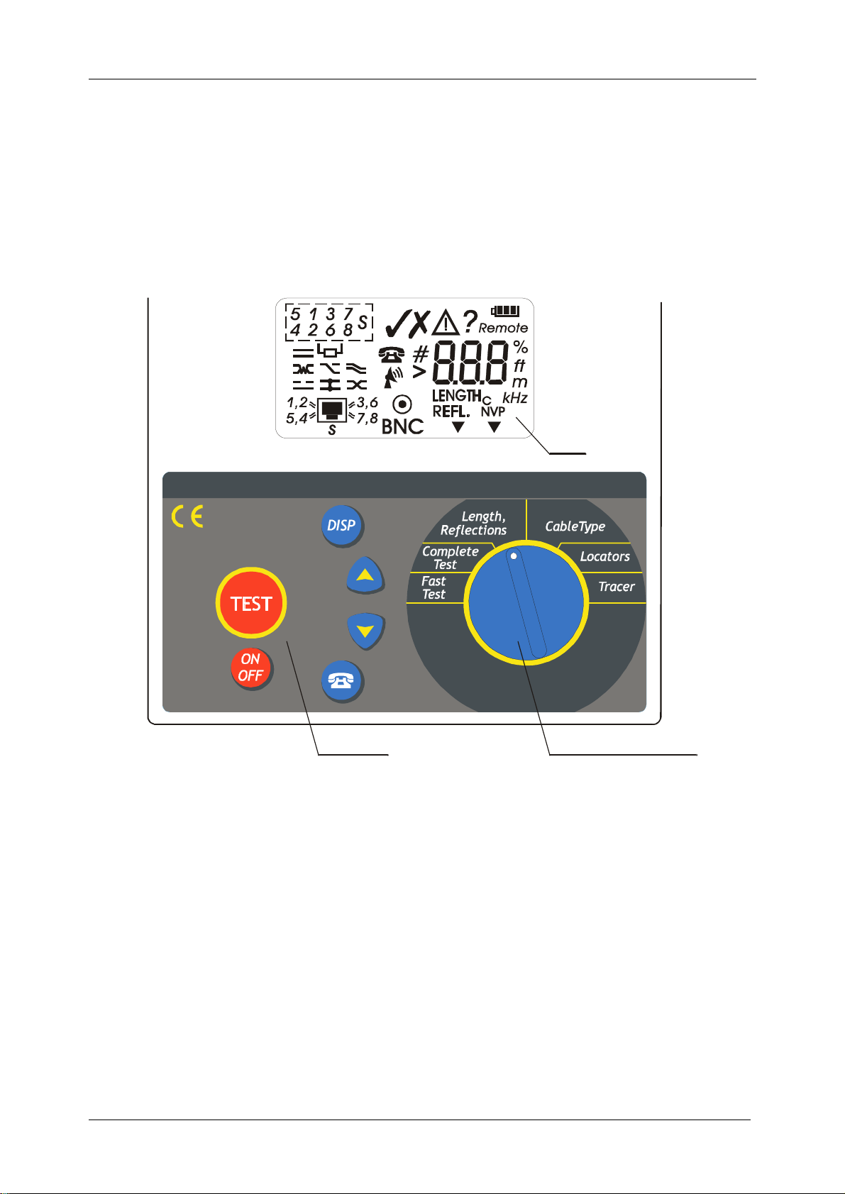
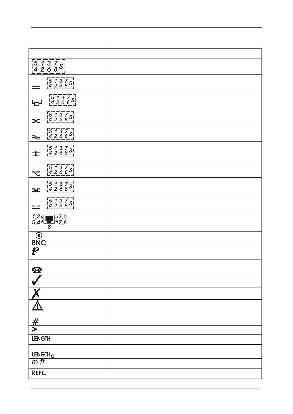
Description of displayed symbols
SYMBOL NAME
Wires/ Pairs result field
Unselected wires / pairs connected
+
Pair terminated
+
Wires reversed
+
Pair crossed
+
+
Wires/ pairs shorted, short to shield
Unknown connectivity fault
+
+
+
Splited pair
Broken / open wire, shield
Selected twisted pair cable standard / type
Coax cable selected
Tone Generator active
Talk & Trace function active
Test passed
Test failed
Warning (redundant pairs / reflections detected)
Cable Identification Number is displayed
Result out of limit
Distance / Amplitude of length is displayed
,
NVP calibrated on known cable length (for precize
length mesurements)
Meters, feets
Distance / Amplitude of reflection is displayed
Page 10
MI 2014 Cable Scanner Section I General information
10
4
3
5
20 224 411
Nominal velocity of pulse is displayed
Faults / Reflections / Redundant connections are
displayed
Disconnect the Remote unit (Fast Test) / No Remote
detected (Complete Test)
Battery indication (change battery if no segment is
displayed)
3.2 Connector panels
2
1. RJ 45 connector
2. BNC connector
3. Audio jack: Microphone input
4. Audio jack: Phone output
5. External charger input
1
3.3 Bottom
3
2
1
Bottom View Layout
1. Information label
2. Battery compartment cover
3. Retaining screws (unsrew to replace batteries)
Page 11

MI 2014 Cable Scanner Section I General information
11
¸3
1
4. Standard remote units description
1. Male RJ 45 plug
2. Female RJ 45 connector
3. Identification number
5. Talk remote unit description
1. Female RJ 45 connector
2.Audio jack: Microphone input
3.Audio jack: Phone output
4. Battery compartement
5. On/Off switch
5
2
4
Page 12

MI 2014 Cable Scanner Section II Specifications
12
Section II Specifications
6. Standard set
Cable Scanner
Cat 5 Patch Cable Metrel PC-2, 1pc
Standard Remote #1
Locators #1 - #4
Cable Scanner User Manual
Calibration Certificate
List of warranty
Declaration of conformity
7. Optional accessories
Talk Remote Unit set
Headphones set
Standard remote set #2-#6
Standard remote set #7-#15
Battery charger with NiCd battery pack
Locator set II (#5..#16) A 1044
Locator set III (#17..#28) A 1045
Tracer
Ordering number
MI2014
S 2004
S 2005
S 2006
A 1082
Page 13

MI 2014 Cable Scanner Section II Specifications
13
8 Technical specifications
8.1 Fast Test
RJ45 output only
Length (highest distance of all pairs is shown, refer to 3.3 for accuracy)
Detection of:
- broken wire on connector or cable + distance to fault
- short between wires + distance to fault
- short to shield
- split pairs
- cable termination
8.2 Complete Test (with Remote units)
RJ45 output only
Length (highest distance of all pairs is shown, refer to 3.3 for accuracy)
Detection of:
- broken wire on connector or cable + distance to fault
- short between wires + distance to fault
- short to shield
- splited, crossed, reversed, transposed pairs
Cable identification #1 - #15
8.3 Length & Reflections
Measuring principle: Time Domain Reflectometer
Output impedance: 100Ω RJ45 output, 50Ω BNC output
Twisted Pair cable
Distance Resolution Accuracy
0.0 – 99.9m
100 – 300m
Amplitude Range
-99% - 100% 1% ±(5%+5dig) of reading
Coax cable
Distance Resolution Accuracy
0.0 – 99.9m
100 – 300m
Amplitude Range
-99% - 100% 1% ±(5%+5dig) of reading
Calibration (see page 20)
Calibration cable length adjustable 2m – 200m
Propagation velocity rate (NVP) adjustable 0.50-0.99
0.1m
0.1m
±(3%+5dig) of reading
±(5%+1dig) of reading
±(3%+5dig) of reading
±(5%) of reading
Page 14

MI 2014 Cable Scanner Section II Specifications
14
Up to three highest reflections (faults) are reported.
Additional error sources that must be considered when measuring length:
Uncertainity of NVP (nominal propagation speed)
Pulse attenuation at high frequencies effects the accuracy at long distances (over
100m).
Accuracy of length is defined on opened, shorted and with remote unit terminated
cables only.
8.4 Locators
Locators #1 - #28
8.5 Tracer
Tone generator frequency 0.80kHz..1.20kHz
Tone generator amplitude RJ45 output: 7V
BNC: 5V
Page 15

MI 2014 Cable Scanner Section II Specifications
15
9. General specifications
9.1 General Data
Display: custom, 85 segments
Operating temperature range: 5°C÷40°C
Storage temperature range: 0°C÷70°C
Relative humidity: 90% up to 40°C declining to 70% up at 45°C
Pollution degree: 2
Protection degree: IP44
Power supply main unit:
6x1.5V AA alkaline batteries or
6x1.5 NiCd or NiMH AA rechargeable batteries
Charger input (nominal charge voltage): 9V=
Typical battery life (alkaline batteries): 10 hours
Talk remote unit supply:
9V alkaline battery
Typical battery life (alkaline battery): 25 hours
Auto Off time: 10 min
Standards applied: EMC: EN50081-1,EN50882-1
Safety: EN61010-1
9.2 Output connector, patch cable wiring: T568B
Pair 1: wire 5, blue-white
wire 4, blue
Pair 2: wire 1,orange-white
wire 2, orange
Pair 3: wire 3, green-white
wire 6, green
Pair 4: wire 7,brown-white
wire 8, brown
Page 16

MI 2014 Cable Scanner Section III Cable Scanner operation
16
Section III Cable Scanner operation
10. Fast test
The Fast Test function enables fast and convenient checking of the installation. Its main
advantage is that the test can be performed by one person, without using the Remotes.
Most likely connectivity faults like bad contacted connector and shorts between wires
can be found with Fast Test. The cable length is also reported, together with the
distance to eventual problems.
We recommend to use this test for fast connectivity checks during bulding of the
installation.
For thorough cable connectivity tests the Complete Test should be used.
For thorough cable quality tests the Length&Reflections function should be used.
Typical Cable Scanner connections in Fast Test
Test procedure
1. Select Fast Test with rotary switch.
2. Check the selected cable type and pin configuration (refer to chapter 8 for more
information), Connect the cable under test to the instrument and press .
If the test passed succesfully following items
are displayed:
- the sign
- the cable length
- correctly connected wires
test successfully passed
Page 17

MI 2014 Cable Scanner Section III Cable Scanner operation
17
If one or more faults are detected following
items are displayed:
- the and signs
- correctly connected pairs
- length if available (depends on the kind of
the fault)
test failed, wires 5,1,2,3,6,7 correctly connected
The related wires, type and distance to fault
(if available) can be viewed by using and
keys. During displaying faults the sign
is displayed.
test failed, shorted wires 4 and 8 at 2.2m
If the test passed succesfully on the cable
pairs defined in selected Cable Type but
other connections were found that are not in
accordance with the defined cable type
following items are displayed:
- the and signs
- the cable length
test conditionally passed, unselected connected
wires detected
- correctly connected pairs
The redundant wire and pairs connections
can be viewed by using and keys.
During displaying them the sign is
displayed.
test conditionally passed(shorted wires 4 and 8 at
2.2m. The wires are not determined in the selected
cable type)
test conditionally passed (Pair 4 is connected. The
pair is not determined in the selected cable type)
Note:
The Fast Test is considered to be performed on cables opened at the far end. If the
cable is terminated by a hub the termination is detected and displayed as a fault.
If a Remote is connected at the far cable end Remote is displayed and the test is not
performed.
Fast Test is not applicable when BNC output is selected.
Broken wires (inside the length tolerances) close to the the far end can't be detected
with this test.
Length can't be measured on terminated cables.
Page 18

MI 2014 Cable Scanner Section III Cable Scanner operation
18
11. Complete test
Complete test checks the installation against all possible connectivity faults. Beside the
complete connectivity test the cable identification and cable lenght are performed.
Remote units must be connected to the far cable end while performing Complete Tests.
We recommend to use this test after the installation is built and before certifying it.
For thorough cable quality tests the Length & Reflections function should be used.
Typical Cable Scanner connections in Complete Test
Test procedure
1. Select Complete Test with rotary switch.
2. Check the selected cable type and pin configuration (refer to chapter 8 for more
information). One of the Remote Units must be connected at the far cable end.
Connect the cable under test to the instrument and press .
If the test passed succesfully following items
are displayed:
- the sign
- the identification number
- correctly connected wires
test successfully passed
With the key it can be switched between length and identification number (if
available).
If one or more faults are detected following
items are displayed:
- the and signs
- correctly connected pairs
- the identification number if available
(depends on the kind of the fault)
test failed, wires 1 to 8 correctly connected
Page 19

MI 2014 Cable Scanner Section III Cable Scanner operation
19
The related wires, type and distance to fault
(if available) can be viewed by using and
keys. During displaying faults the sign
is displayed.
test failed, shield is broken or not connected
If the test passed succesfully but additional
connections were detected that are not
defined in the set Cable Type following
items are displayed:
- the and signs
- the identification number if available
- pairs connected according to the set type
test conditionally passed, unselected connected
wires 1,2,3,6 detected
By using key it can be switched between length and identification number (if
available).
The redundant wire and pairs connections
can be viewed by using and keys.
During displaying them the sign is
displayed.
test conditionally passed (pair 2 is connected. The
pair is not determined in the selected cable type)
Note:
If no Remote Unit is connected at the far cable end ? Remote is displayed.
Remotes #1 - #5 are applicable on all cable types.
Remotes #6 - #15 are applicable only on cables where all 4 pairs are used.
Complete Test is not applicable when BNC output is selected.
Page 20

MI 2014 Cable Scanner Section III Cable Scanner operation
20
12. Length and reflections
This function enables accurate cable length and quality measurements. Up to 3 largest
reflections caused by cable damages, impedance mismatches or other reasons are also
detected.
There are many applications where the Length & Reflection test can be used
- checking new cables against possible damages
- checking cable lengths
- determining location of cable problems (broken, shorted, damaged cable)
- checking connection and junction points quality
The in built Time Domain Reflektometer provides the distance and amplitude
information of
reflected pulses. That helps to determine the reason of cable problem.
Typical Cable Scanner connections in Length & Reflections Test
Amplitude information
The amplitude of the reflected pulses is available as a subresult providing important
information about the cause of problem (exessive attenuation, shorted or open end,
improper termination, unproper connector assembling etc) – see pictures below.
100% equals the amplitude of the pulse at the output connector into a 100Ω UTP Cat 5
cable.
Pulse length, reflections
Due to cable attenuation along the cable the reflected pulse weakens when the distance
increases.
Three pulse lenghts are used to compensate for the cable attenuation.
Special algorithms are used to evaluate the 3 largest reflections regardless of the pulse
energy and to differ between length and reflections.
Page 21

MI 2014 Cable Scanner Section III Cable Scanner operation
21
amplitude
no result line
no result line
no result line
no result line
Principle of Cable Scanner Length&Reflections operation
To encounter the attenuation effect the reflections amplitudes are compared to the
normal attenuation line. This means that a reflection with smaller amplitude at higher
distance can be treated as higher then a reflection with higher amplitude at the begin of
the measuring range.
Reflections below the No result line are ignored.
+100%
-100%
amplitude
+100%
-100%
25.1 m
n
o
r
m
n
a
l
a
Reflection
a
m
r
o
n
o
r
m
r
o
n
tt
e
n
u
a
t
io
no result
no result
u
n
te
t
a
l
a
l
a
t
te
n
e
t
t
a
l
a
m
n
l
i
n
e
distance
25 m
e
n
i
l
n
o
i
t
a
u
a
t
io
n
li
n
e
distance
150 m
e
n
i
l
n
o
i
t
a
u
n
amplitude
+100%
n
o
r
m
a
l
a
t
te
n
u
a
t
i
o
n
li
n
e
distance
150 m
e
n
i
l
n
o
i
t
a
u
n
te
t
a
l
a
m
r
o
-100%
n
300 m
Page 22

MI 2014 Cable Scanner Section III Cable Scanner operation
22
Lenght (open cable end)
Refl.2
Lenght (shorted cable end,terminated with remote)
no result ( cable lenght >300m or cable terminated)
Some typical TDR results
Lenght
Lenght
Refl 1: problem at the
near end connector
Length and Reflections Test procedure
1. Select Length&Reflections function with rotary switch.
2. Check the selected cable type (refer to chapter 8 for more information).
3. Connect the tested cable to the instrument and press .
If the test passed succesfully following items
are displayed (the lengths of measured
pairs should not differ for more then
5%±0.5m):
- the sign
- the length of the displayed pair
length test successfully passed
Page 23

MI 2014 Cable Scanner Section III Cable Scanner operation
23
If the test failed because of different lengths
of measured pairs following items are
displayed:
- the sign
- the length of the displayed pair
length test failed
By using the key it can be switched between length and amplitude. Before amplitude
the pulse
length (short , middle , long ) is displayed for 0.5s.
By using and keys the lenghts or amplitudes of other pairs are displayed.
Note
(If different pair lengths were measured with different pulse lengths differences in
amplitude can occur. The operater must consider this effect when comparing
amplitudes.)
If the length test (lengths of measured pairs
are not differ for more then 5%±0.5m)
passed succesfully but additional (one to
three) reflections are detected following
items are displayed
- the and signs
- the length of the displayed pair
length test successfully passed, additional reflections
are detected
If the length test fails and additional
reflections are detected following items are
displayed:
- the and signs
- the length of the displayed pair
length test failed, additional reflections are detected
By using and keys the lengths of other measured pairs and reflections are
displayed.
By using the key it can be switched between distance and amplitude. Before
amplitude the pulse length (short , middle , long ) is displayed for
0.5s.
Some typical subresult screens are shown below:
amplitude of length of pair 3,
additional reflections are detected
distance to the exessive reflection
on pair 2
amplitude of the exessive
reflection on pair 2
Page 24

MI 2014 Cable Scanner Section III Cable Scanner operation
24
12.1 Cable Length Calibrations
The accuracy of the length measurement is calculated from the time it takes the pulse to
travel along the cable and reflect back to the instrument. For this reason the cable NVP
(nominal velocity of pulse propagation) must be known. Cable NVP factors differs
between different cable types and are further influenced by ageing and temperature. By
using the Length Calibration this errors are eliminated and very precize length
measurements can be performed.
Two calibration types are available with Cable Scanner:
- Calibrations based on known NVP. Use this calibration when the exact NVP factor is
known from the manufacturer data sheet or others.
- Calibration based on known cable length. In this mode the NVP is calculated from a
cable sample of known length. Best results can be obtained this way especially if
performing the calibration on the same cable or cable of the same type.
Setting a new (known) NVP factor manually
1. After selecting Length&Reflections with
rotary switch press twice . The 'NVP
Calibration' screen is displayed.
2. Select new NVP factor with / key.
NVP calibration display
3. Press . After that the new NVP is
displayed NVP factor
displayed for about 1 second together
with the sign.
Checking the set NVP factor (without changing it)
1. After selecting Length&Reflections with rotary switch press twice to enter the 'NVP
Calibration' screen.
2. Press or key once. The currently set NVP is displayed.
3. Press to return to basic screen without changing the settings.
Setting a new NVP on base of a known cable length
Best results are obtained when performing a calibration on the same cable or cable type
on a known length.
Page 25

MI 2014 Cable Scanner Section III Cable Scanner operation
25
1.Select Length&Reflections with rotary
switch and press afterwards. The 'Length
Calibration' screen is displayed.
NVP calibration display
2.Connect the cable of known length to the
instrument and set the length with /
keys. The cable must be opened or
shorted at the far end.
set known cable length
3. Press . The calibration is successfully
performed if the new NVP is displayed for
about 1 second and the C subscript
appears near the length sign, together
with the sign.
successfully performed calibration
Otherwise the sign together with the length measured with the former set NVP is
displayed for about 1 second (if the calculated NVP lies outside the 0.5 – 0.99 range
because of incorrect length set).
Note:
Any other action than pressing
will cancel the calibration.
The set NVP (C subscript near the length sign) stays in memory until a new NVP is
manually corrected or the instrument is reinitalized to default values (default NVP=0.69).
Page 26

MI 2014 Cable Scanner Section III Cable Scanner operation
26
#16
13 Locators – Identification of cables
Test procedure
Locators are used for finding the correct cable connector in wiring closets, patch panels
etc. In this mode the instrument decodes which identificator is connected to the far
cable end.
28 simple Locators are available for fast and simple cable identification.
1. Select Locator function with the rotary
switch.
2. Connect the coded (the code is printed
on the locator) locators in far cable end
sockets.
On the display the code of the locator on the
far cable end is shown.
#1#2#3
Locator 13 connected at the other cable side
Typical Cable Scanner connections in Locators Test
Important
The Standard Remotes and Talk Remote can’t be used instead of Locators.
Page 27

MI 2014 Cable Scanner Section III Cable Scanner operation
27
locating cables in patch panels
14. Tracer – Tracing of cables and wires
The in built tone generator can be used together with different Tracers for identifying
cable pairs, conductors within a bundle, tracing cables under walls etc.
Test procedure
1. Select Locator function with the rotary
switch and press to enter Tracing
screen. Check if the correct cable type is
selected.
2. When using the RJ45 output the cable
pair in which the tone signal is generated
tone generator emittes the signal in pair 4
can be select by using / keys.
Refer to Tracer instructions for more information about tracing cables, wire pairs etc.
Typical Tracer applications
tracing cables under wall
determining wires in
a bundle
Typical Cable Scanner connections in function Tracer
Page 28

MI 2014 Cable Scanner Section III Cable Scanner operation
28
15. Talk & Trace function
The in built Talk & Trace interface enables full duplex voice communication over the
cable when using the Talk Remote Unit. The communication works perfectly regardless
of the cable length and attenuation.
The interface can be used also for determining and locating cables. After the Talk
Remote Unit
connects with Cable Scanner a connection 'beep' is heared on both units. No
headphones are used
in this case.
Cable Scanner connection during voice communication
15.1 Establishing a voice communication
Before talking both operators must put on the headphones. Both jacks (mic and phone)
must be plugged in both units.
.
1. The function Talk & Trace is set by
pressing the key regardless of the
function currently set . The ''Searching''
sign is moving on the display and the
Cable Scanner tries to connect itself with
the Talk Remote unit.
2. After the Remote unit is found and
successfully connected PHO is displayed
together with a confiramtion beep and the
communication can begin.
At the same time the Talk LED on the
Talk Remote Unit lights up together with
a confirmation beep.
If the communication between both units is broken off (e.g. when changing to another
plug in a patch panel) the main unit returns to ''Searching'' mode so the communication
can proceed immediately after the Talk Remote Unit is reconnected to the same cable
as the instrument..
Talk Remote unit detected at the far cable end
Talk&Trace ‘searching’ mode
Page 29

MI 2014 Cable Scanner Section III Cable Scanner operation
29
15.2 Breaking off the connection
The connection can be concluded at any time from the Cable Scanner by pressing
key again. The instrument returns to the state it was before the connection.
15.3 Locating cables
The procedure described in 6.1 and 6.2 can be used when locating cables in patch
cables, computer rooms etc. This can be done without using headphones.
Note:
At least one pair must be connected correctly to ensure proper operation.
The 'Searching sign' is moving very slowly if a Standard Remote is connected at the far
cable end (communication is not possible).
15.4 Talk Remote Unit operation
The Talk Remote Unit can be used as a Standard Remote Unit for performing Complete
cable connectivity and identification tests (refer to chapter 2).
The in built Talk & Trace interface enables full duplex voice communication with the
Cable Scanner during performing cable tests.Two LEDs indicate the current unit status.
Test mode
When powered ON the Talk Remote Unit behaves same as the Standard Remote Unit
#1.
Talk mode
The Talk Remote Unit automatically switches to 'Talk' mode when the Talk command
from the instrument is detected. The TALK LED lights on and a confirmation beep
indicates that both units are connected.
This allows the operator on the remote side to recognize that the operator on the main
side wants to establish a voice connection (Main unit is set in Talk & Trace mode) and
that the Talk Remote Unit was found. Use headphones to communicate. After both units
are disconnected or the Talk&Trace mode on the instrument is left the TALK LED
extinguishes.
Low battery indication
Flashing Power LED indicates that the supply voltage is too low for proper operation.
The power supply battery must be changed.
Page 30

MI 2014 Cable Scanner Section III Cable Scanner operation
30
16. Cable type
In this menu the active output (RJ45 or BNC) connector and different cable
standards/types can be set. The selected cable type is displayed in all functions
(excepting the Locator function)
For some cable and communication standards just two of four twisted pairs are used.
Shielded (STP, ScTP, FTP), unshielded (UTP) twisted pair cables and coax cables can
be set depending on the application.
Selecting the right cable type and standard easifies the Fast and Complete Tests since
nonselected pairs and shield are ignored in the / judgment. The sign.is
displayed if wires or pairs not defined in the selected cable type are connected.
Selecting connector output and cable type/standard
1. Select Cable Type position with the rotary
switch. The latest set cable type/standard
is displayed.
2. Select a new cable type with / key
(6 different types RJ45 outputs and BNC
output are available). The currently
displayed type/standard remains in
memory until selecting a new one or
reinitializing the instrument.
4 twisted pairs shielded cable selected
BNC cable selected
Page 31

MI 2014 Cable Scanner Section III Cable Scanner operation
31
17. Reinitialisation (setting default values /
length unit )
The default set cable type, default NVP factor and length unit are set if reinitalizing the
instrument.
Press
afterwards. Any other action that pressing
key while powering on the instrument (rES is displayed) and press
will break off the reinitalisation .
Deafult Cable Type: UTP , all 4 pairs connected
Default NVP factor : 0.69
Default length unit: meters
The length unit can be set by pressing the
Select the unit with / keys and press afterwards.
key while powering up the instrument.
In the table below typical NVP values for some popular cable types can be found.
Cable Standard Cable Type NVP
Class C, Class D, Cat 5, Cat 5E UTP, ScTP, STP, FTP
100Ω
STP 120Ω
STP 150Ω
Cat 4
Cat 3
Coax Cables
UTP, ScTP 100Ω
UTP, ScTP 100Ω
Coax 10Base2 50Ω
Coax 10Base 5 50Ω
Coax RG58 50Ω
Coax RG8 50Ω
Coax RG59 75Ω
Coax RG62 93Ω
0.69
0.69
0.78
0.66
0.62
0.67
0.78
0.74
0.84
0.78
0.84
Page 32

 Loading...