

Page 1

Europrove
CS 2090
Instruction manual
Version 1.1, Code No. 20 751 588
Page 2

Distributor:
Manufacturer:
METREL d.d.
Ljubljanska cesta 77
1354 Horjul
Slovenia
web site:
http://www.metrel.si
e-mail: metrel@metrel.si
Mark on your equipment certifies that this equipment
meets the requirements of the EU (European Union)
concerning safety and electromagnetic compatibility
regulations.
© 2009 METREL
No part of this publication may be reproduced or utilized in
any form or by any means without permission in writing
from METREL
2
Page 3

CS 2090 Europrove
1.Introduction .............................................................................4
1.1 General Description...................................................4
1.2 Applied Standards .....................................................4
1.3 Warnings ...................................................................4
1.4 Europrove description................................................5
2 Europrove operation ...............................................................6
2.1 Application.................................................................6
2.2 Test procedure...........................................................6
3. Maintenance ..........................................................................8
3.1 Battery replacement...................................................8
3.2 Cleaning ....................................................................8
3.3 Service.......................................................................8
4. Standard set...........................................................................9
5. Technical specifications.......................................................10
6 Quick start guide...................................................................11
3
Page 4

CS 2090 Europrove
1.
Introduction
1.1 General Description
The Europrove unit is applicable for checking the operation
of two pole voltage testers and multimeters.
1.2 Applied Standards
Safety EN / IEC 61010-1
EMC compatibility EN / IEC 61326
1.3 Warnings
In order to reach the highest level of operator safety while
carrying out tests with the CS2090 Europrove please
consider following warnings:
• Warning on the unit means “Read the
Instruction manual with special care for safe
operation.” The symbol requires an action!
• Never connect outputs on live circuits!
• If the test equipment is used in a manner not
specified in this User Manual, the protection
provided by the equipment may be impaired!
• The Europrove unit can only be used with test
leads according to EN / IEC 61010 – 31.
• Do not use the Europrove unit if any damage is
noticed!
• Ensure that the unit is free from moisture and
clean.
• Only a competent and authorized person should
carry out any service intervention!
• The unit generates a dangerous high voltage on
both outputs so all generally known precautions
should be taken in order to avoid the risk of
electric shock.
4
Page 5

CS 2090 Europrove
1.4 Europrove description
Legend:
1. Voltage indicators
(LEDs)
2. Low battery indication
(LED)
3. Output terminal (Start)
4. Output terminal (50 V
AC)
5. Output terminal (500 V
DC)
6. Screws for removing
battery cover
7. Battery compartment
Figure 1 Europrove unit - legend
5
Page 6

CS 2090 Europrove
2 Europrove operation
2.1 Application
According to HSE and NICEIC recommendations it must be
verified:
• that the installation is de-energized before carrying out
electrical testing (continuity, insulation resistance).
• after reconnection of the installation back to the mains
supply the presence of voltage and correct polarity of
conductors should be verified.
The simplest way to perform the test is to check the
voltages with a voltage checker.
Wrong results of the voltage checks could have fatal
consequences hence the electrician must be 100% sure
that the voltage checker works properly. The checker’s
operation should be verified before and after doing any test.
The procedure is as follows:
Step 1: Verify correct operation of the voltage indicator
Step 2: Perform voltage check with the voltage indicator
Step 3: Verify correct operation of the voltage indicator
again.
The CS 2090 Europrove is a simple and efficient tool for
checking the correct operation of voltage indicators and
multimeters.
2.2 Test procedure
Step 1:
The voltage checker can be tested by placing both probes
in the appropriate CS 2090 Europrove output terminals
Step 2:
To activate the Europrove unit, the Start terminal contact
switch must be closed.
It is good practice to make the Start terminal contact first.
Until the other output terminal (50 V AC or 500 V DC) is
closed, the voltage generator is unloaded and all voltage
indicators on the Europrove unit should be lit.
After making the second contact the generator will become
loaded by the voltage checker. Some voltage checkers
represents a relatively large load at the beginning so it can
happen that the voltage indication is low at the beginning
and rises slowly to its final value.
Step 3:
After the indication on the Europrove stabilizes, check the
reading / indication of the voltage checker.
6
Page 7

CS 2090 Europrove
Step 1 Step 2
Step 3
Example of Europrove test application (voltage checker)
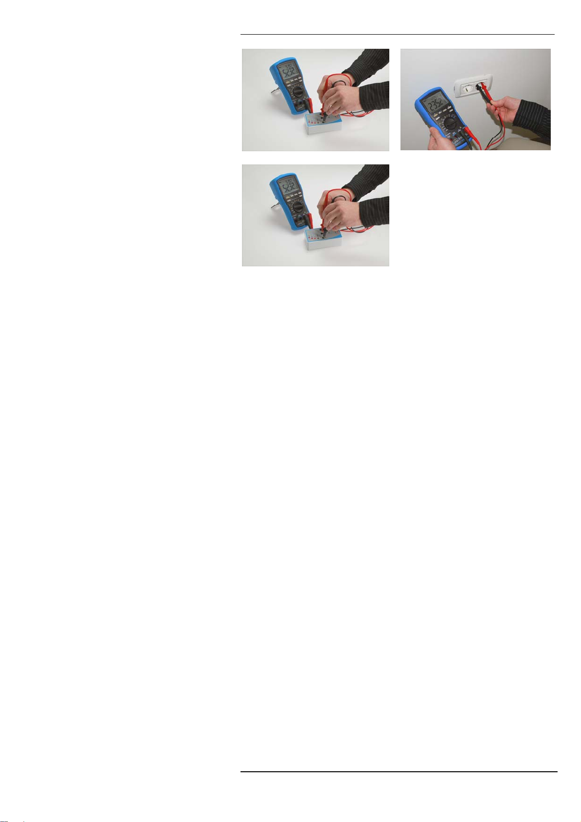
Step 1 Step 2
Step 3
Example of Europrove test application (multimeter 50 V AC)
Note:
• The power consumption due the test is relatively high
therefore it is recommended to use high quality
alkaline or NiMH batteries.
• The 50 V AC output is primarily intended to check
the VAC operation mode of multimeters
• The LED indication relates to the 500V output.
7
Page 8

CS 2090 Europrove
3. Maintenance
3.1 Battery replacement
Low battery state is indicated by Low battery LED flashing
when battery voltage drops below 5.6 V approx. In this
situation the batteries must be replaced to ensure voltage
outputs are inline with the technical specifications. The
Europrove unit uses six AA size alkaline or rechargable
NiMH battery cells.
(See figure 1)
• The unit generates a dangerous high voltage
on both outputs so all generally known
precautions should be taken in order to avoid risk
of electric shock.
• Do not switch on the unit during battery
replacement until battery cover is replace.
• The batteries should only be replaced with the
same type as defined on battery cover or in this
manual.
• Ensure that the battery cells are inserted correctly
otherwise the unit will not operate and the
batteries could be discharged.
• All six battery cells should be changed for new
when batteries are replaced.
• If the unit is not to be used for a long period of
time, remove all batteries from battery
compartment.
3.2 Cleaning
To clean the surface of the unit use a soft patch slightly
moistened with soapy water or alcohol. lThen leave the unit
to dry totally before use
• Do not use liquids based on petrol or
hydrocarbons!
• Do not spill cleaning liquid over the unit!
3.3 Service
In case of any malfunction or damage noticed on the unit, a
competent service department must service the instrument.
Contact your dealer for detailed information.
8
Page 9

CS 2090 Europrove
4. Standard set
Europrove CS 2090 unit
Instruction manual
Warranty declaration
9
Page 10

CS 2090 Europrove
5. Technical specifications
Output voltage:
Output 500 V
Output 50 V
Voltage, frequency accuracy..............± 10%
Short circuit current:
Output 500 V
Output 50 V
Voltage indicators...............................>20 V, >200 V, > 400 V
Power supply voltage .........................9 V
Operation............................................minimal 300
Protection classification......................double insulation
Protection degree case ......................IP 40
Protection test outputs........................IP 20
Weight………………………...............160 g
Dimensions (w x l x h)………………..68 mm x 125 mm x 40 mm
...........................................................
Operating conditions:
Working temperature range................0
Maximum relative humidity.................95 %RH, non-condensing
Storage conditions:
Temperature range.............................-10
Maximum relative humidity.................90 %RH (-10
...........................................................80 %RH (40
(unloaded).................500 VDC+ 50 V
DC
(unloaded)................................. 50 V
AC
...................................< 40 mA
DC
........................ ……….2.8 mA
AC
(6×1.5 V battery or
DC
accu, size AA)
measurements, (depends
on type of voltage checker)
°C ÷ 40 °C
°C ÷ +70 °C
/ 50Hz
AC
/ 50Hz
AC
°C ÷ +40 °C)
°C ÷ 60 °C)
10
Page 11

CS 2090 Europrove
6 Quick start guide
TEST PROCEDURE
Step 1:
The voltage checker can be tested by placing both probes
in the appropriate Europrove output terminals.
Step 2:
To activate the Europrove unit, the Start terminal contact
switch must be closed.
It is good practice to make the Start terminal contact first.
Until the other output terminal (50 V AC or 500 V DC) is
closed, the voltage generator is unloaded and all voltage
indicators on the Europrove unit should be lit.
After making the second contact the generator will become
loaded by the voltage checker. Some voltage checkers
represents a relatively large load at the beginning so it can
happen that the voltage indication is low at the beginning
and rises slowly to its final value.
Step 3:
After the indication on the Europrove stabilizes check the
reading / indication of the voltage checker.
Step 1 Step 2
Step 3
Example of Europrove test application (voltage checker)
11
Page 12
CS 2090 Europrove
Step 1 Step 2
Step 3
Example of Europrove test application (multimeter 50 V AC)
12
 Loading...