

Page 1
BetaPATPlus MI 3304
OmegaPATPlus MI 3305
User Manual
Ver. 2.1, Code no. 20 751 220
Page 2

2
Distributor:
Producer:
Metrel d.d.
Ljubljanska cesta 77
SI-1354 Horjul
E-mail: metrel@metrel.si
http://www.metrel.si
© 2007 Metrel
Mark on your equipment certifies that this equipment meets the requirements of
the EC (European Community) regulations concerning safety and
electromagnetic compatibility.
No part of this publication may be reproduced or utilized in any form or by any means
without permission in writing from METREL.
Page 3

OmegaPATPlus / BetaPATPlus Table of contents
3
1 General description................................................................................................6
1.1 Warnings ....................................................................................................7
1.2 Warning markings on connector panel .......................................................7
1.3 Standards applied ......................................................................................7
2 Instrument description...........................................................................................8
2.1 Front panel .................................................................................................8
2.2 Meaning of symbols and messages on the instrument display ..................9
2.3 Dual voltage operation (UK model only)...................................................14
3 Technical specifications......................................................................................15
3.1 Earth bond resistance ..............................................................................15
3.2 Insulation resistance.................................................................................15
3.3 Substitute leakage current........................................................................16
3.4 Leakage current and apparent power.......................................................16
3.5 Touch leakage current..............................................................................17
3.6 Polarity test ..............................................................................................17
3.7 Clamp current...........................................................................................17
3.8 Trip-out time of portable RCD ..................................................................18
3.9 Flash test (MI 3305 – OmegaPATPlus only) ............................................18
3.10 General data ............................................................................................18
4 Main menu and test modes..................................................................................20
4.1 Help menus ..............................................................................................20
4.1.1 How to enter help menu ...........................................................................20
4.2 Main menu ...............................................................................................21
4.3 Autotest shortcut menu ............................................................................21
4.4 Autotest custom menu..............................................................................21
4.5 Project autotests menu.............................................................................22
4.6 Single test menu.......................................................................................22
4.7 User / appliance data menu .....................................................................23
4.8 Recall / delete / send results menu ..........................................................23
4.9 Data upload / download menu..................................................................23
4.10 Setup menu..............................................................................................24
5 Single test mode...................................................................................................25
5.1 How to perform measurements in single test mode .................................25
6 Measurements ...................................................................................................... 26
6.1 Earth bond resistance ..............................................................................26
6.1.1 How to perform earth bond resistance measurement...............................26
6.2 Insulation resistance.................................................................................27
6.2.1 Insulation resistance on class I appliances ..............................................27
6.2.2 Insulation resistance on class II appliances .............................................28
6.2.3 How to perform single insulation resistance measurement ......................29
6.3 Substitute leakage current........................................................................30
6.3.1 Substitute leakage current on class I appliances .....................................30
6.3.2 Substitute leakage current on class II appliances ....................................30
6.3.3 How to perform single substitute leakage current measurement..............31
6.4 Leakage current and power......................................................................32
6.4.1 How to perform single leakage current measurement..............................33
6.5 Touch leakage current..............................................................................34
6.5.1 How to perform single touch leakage current measurement ....................34
Page 4

OmegaPATPlus / BetaPATPlus Table of contents
4
6.6 Polarity test ..............................................................................................35
6.6.1 How to perform the measurement............................................................36
6.7 TRMS current measurement using clamp current adapter.......................37
6.7.1 How to perform TRMS current measurement using clamp current adapter
.................................................................................................................37
6.8 RCD test...................................................................................................38
6.8.1 RCD test on appliances............................................................................38
6.8.2 How to perform an RCD test ....................................................................39
6.8.3 How to perform RCD single test...............................................................40
6.8.4 How to perform RCD auto test .................................................................41
6.9 Flash test (MI 3305 – OmegaPATPlus only) ............................................44
6.9.1 Flash test on class I appliances ...............................................................44
6.9.2 Flash test of class II appliances ...............................................................44
6.9.3 How to perform single Flash measurement..............................................44
7 Autotest sequences .............................................................................................46
7.1 Autotest shortcut menu ............................................................................46
7.1.1 Selecting the autotest shortcut sequence.................................................46
7.1.2 How to view autotest shortcut sequence measurement parameters ........47
7.1.3 How to start autotest shortcut sequence ..................................................48
7.2 Autotest custom menu..............................................................................48
7.2.1 How to view and/or change an existing autotest custom sequence .........48
7.2.2 How to save the autotest custom sequence.............................................50
7.2.3 How to delete an existing custom test sequence from the list ..................50
7.2.4 How to start custom autotest sequence ...................................................50
7.3 Project autotests ......................................................................................51
7.3.1 How to select a project autotest ...............................................................51
7.3.2 How to start a project autotest..................................................................53
7.3.3 Compare of results (evaluation of result trends).......................................54
7.4 Performing autotest sequences................................................................55
7.4.1 Visual inspection ......................................................................................55
7.4.2 Earth bond resistance measurement........................................................55
7.4.3 Insulation resistance measurement..........................................................56
7.4.4 Substitute leakage current measurement.................................................56
7.4.5 Leakage current and apparent power measurement................................57
7.4.6 Touch leakage current measurement.......................................................57
7.4.7 Polarity test ..............................................................................................58
7.4.8 TRMS current measurement using clamp current adapter.......................58
7.4.9 RCD test...................................................................................................58
8 Working with autotest results .............................................................................60
8.1 Saving autotest results .............................................................................60
8.2 Recalling results.......................................................................................61
8.3 Deleting results ........................................................................................63
8.4 Downloading and printing results .............................................................64
8.4.1 Communication ports settings for communication with PC.......................66
8.4.2 Settings for generic serial printer..............................................................67
8.4.3 Settings for label printer ...........................................................................68
9 Other instrument operations...............................................................................70
9.1 User / appliance data menu .....................................................................70
9.1.1 Users submenu ........................................................................................70
Page 5

OmegaPATPlus / BetaPATPlus Table of contents
5
9.1.2 Appliances submenu ................................................................................71
9.1.3 Test sites (UK model) / buildings (Aus/NZ model) submenu ....................71
9.1.4 Locations (UK model) / rooms (Aus/NZ model) submenu ........................72
9.2 Data upload / download............................................................................72
9.3 Setup menu..............................................................................................73
9.3.1 Setting date and time ...............................................................................73
9.3.2 Display contrast adjustment .....................................................................74
9.3.3 Print header..............................................................................................74
9.3.4 Language selection ..................................................................................75
9.3.5 Viewing of instrument data .......................................................................75
9.3.6 Instrument settings...................................................................................75
9.3.7 Password .................................................................................................77
9.3.8 Communication settings ...........................................................................78
9.3.9 Reset instrument settings.........................................................................79
10 Maintenance..........................................................................................................80
10.1 Periodic calibration...................................................................................80
10.2 Fuses .......................................................................................................80
10.3 Service .....................................................................................................80
10.4 Cleaning ...................................................................................................80
11 Instrument set and accessories..........................................................................81
Page 6

OmegaPATPlus / BetaPATPlus General description
6
1 General description
OmegaPATPlus / BetaPATPlus is a portable test instrument intended for testing the
electrical safety of portable electrical equipment. The following tests can be performed:
Ì earth bond resistance,
Ì insulation resistance,
Ì substitute leakage current,
Ì differential leakage current,
Ì touch leakage current,
Ì functional test,
Ì IEC cord polarity test,
Ì portable RCD test
Ì flash test (MI 3305 – OmegaPATPlus only),
Ì TRMS leakage and load currents with current clamp.
Some instrument's highlights:
Ì large graphic LCD display with resolution of 240 × 128 dots, with back-light,
Ì over 6500 memory locations in data flash memory for autotest results,
Ì four communication ports (USB and RS232C) for communication with PC,
barcode reader or printers,
Ì soft touch keyboard with cursor keys,
Ì built in real time clock,
Ì fully compatible with new METREL PATLink PRO PCSW package,
Ì best suited for periodic testing,
Ì fast testing with barcode identification systems,
Ì test data can be uploaded from PC,
Ì comparisons between old and new test results can be performed on site,
Ì enables printing of test labels on site.
Page 7

OmegaPATPlus / BetaPATPlus General description
7
1.1 Warnings
In order to reach high level of operator safety while carrying out various measurements
using OmegaPATPlus / BetaPATPlus instrument, as well as to keep the test equipment
undamaged, it is necessary to consider the following general warnings:
Ì Read this user manual carefully, otherwise use of the instrument may be
dangerous for the operator, for the instrument or for the equipment under
test!
Ì If the test equipment is used in manner not specified in this user manual
the protection provided by the equipment may be impaired!
Ì Use only correctly earthed mains outlets to supply the instrument!
Ì Do not use the instrument and accessories if any damage is noticed!
Ì In case a fuse has blown follow the instructions in this user manual to
replace it!
Ì Instrument servicing and calibration is allowed to be carried out only by a
competent authorized person!
Ì Use only standard or optional test accessory supplied by your distributor!
1.2 Warning markings on connector panel
Refer to chapter 2.1 Front panel.
1.3 Standards applied
The OmegaPATPlus / BetaPATPlus instrument has been manufactured and tested in
accordance with the following standards:
Safety:
Ì EN 61010-1
Ì EN 61010-31
Electromagnetic compatibility (emission and immunity):
Ì IEC 61326
Measurements in accordance with:
Ì British standard BS89
Ì German standards VDE 0701 and VDE 0702
Page 8

OmegaPATPlus / BetaPATPlus Instrument description
8
2 Instrument description
2.1 Front panel
Front panel
Legend:
1..............Mains switch with indication lamp.
2..............Two T16 A / 250 V fuses for instrument protection.
3..............Mains supply cord.
4..............240 × 128 dots graphic matrix display with backlight.
5..............LN and PE sockets for testing the insulation resistance and substitute leakage
current of fixed installed appliances.
Warning! These sockets are intended only for the connection of
deenergized appliances.
6..............Flash test socket
7..............PRCD socket for testing portable residual current devices
Warning! This socket is intended only for connection of portable RCDs.
8..............IEC appliance connector for testing supply cords.
Warning! The connector input is only for testing purposes; do not
connect it to mains supply!
9..............Test probe (earth bond) connector, also used as an input in some class 2
measurements:
insulation resistance, substitute and touch leakage currents (reffered to as
socket S)
10............Test socket (115 V),
Warning! Dangerous voltage is present on the test socket during the
measurement. Maximum output current is 16 A, test only appliances
with maximum rated supply current not higher than 16 A!
11............Test socket (230 V).
Warning! Dangerous voltage is present on the test socket during the
measurement. Maximum output current is 16 A, test only appliances
with maximum rated supply current not higher than 16 A!
12............Cursor keys and ENTER key.
Page 9

OmegaPATPlus / BetaPATPlus Instrument description
9
13............Alpha-numeric keyboard.
14............STOP key.
15............START key.
16............ESCAPE key.
17............Current clamp adapter input sockets.
Warning! Do not connect any voltage source on this input. It is intended
only for connection of current clamp with current output. Maximum
input current is 30 mA!
18............Function keys.
19............USB connector.
20............PC / printer connector.
21............Barcode reader connector.
22............Label printer connector on back side (support for PrintekMobile MtP300 /
MtP400 serial printer).
Safety pre-tests
Before performing a measurement, the instrument performs a series of pre-tests to
ensure safety and to prevent any damage. These safety pre-tests check for:
Ì any external voltage against earth on test socket,
Ì excessively high leakage current,
Ì excessively high touch leakage current,
Ì short circuit or too low resistance between L and N on appliance,
Ì correctly applied mains voltage to the test socket.
If pre-tests fail, an appropriate warning message will be displayed.
The warnings and measures that have to be taken are described in chapter 2.2
Meaning of symbols and messages on the instrument display.
2.2 Meaning of symbols and messages on the instrument
display
Mains voltage is not
correct or PE is not
connected.
Check mains voltage
and PE connection!
Improper supply voltage warning. Possible causes:
Ì no earth connection or other wiring problem on
supply socket.
Ì incorrect mains voltage.
Determine and eliminate the problem before
proceeding!
Page 10

OmegaPATPlus / BetaPATPlus Instrument description
10
L and N are crossed.
Press START key to
continue.
The instrument works normally also in the case when L
and N are interchanged. Check polarity of line and neutral
wires on test socket.
Warning!
Mains voltage is not correct
or PE not connected or 110 V
centre tapped / IT system.
Press START key to continue
if 110 V centre tapped / IT
system.
Improper supply voltage warning. Possible causes:
Ì no earth connection or other wiring problem on
supply socket,
Ì instrument connected to 110 V centre tapped or IT
earthing supply system.
Press the START key to continue if instrument is
connected to 110 V centre tapped or IT supply system.
Warning!
Instrument is connected to
the IT earthing system or PE
not connected.
Press START key to
continue.
Supply voltage warning. Possible causes:
Ì no earth connection,
Ì instrument connected to IT earthing system.
Press the START key to continue if instrument is
connected to IT earthing system.
Resistance L – N too
high (>30 kΩ).
Check fuse and switch.
Are you sure to
proceed? (Y/N)
An excessively high resistance was measured in the fuse
pre-test. Indication means that appliance has too low
consumption or is:
Ì not connected,
Ì switched off,
Ì contains a fuse that has blown.
Select YES or NO with Y or N key.
Resistance L – N low.
Are you sure to
proceed? (Y/N)
A low resistance of the appliance’ supply input was
measured in the pre-test. This means that it is very likely
that an excessively high current will flow after applying
power to the tested appliance. If the high current is only of
short duration (caused by a short inrush current) the test
can be performed, otherwise not.
Select YES or NO with Y or N key.
Page 11

OmegaPATPlus / BetaPATPlus Instrument description
11
Resistance L – N too
low.
Are you sure to
proceed? (Y/N)
An extremely low resistance of the appliance’ supply input
was measured in the pre-test. It is likely that fuses will
blow after applying power to the tested appliance. If the
too high current is only of short duration (caused by a
short inrush current) the test can be performed otherwise it
must be stopped.
Select YES or NO with Y or N key.
It is recommended to additionally check the appliance
before proceeding with the test!
Leakage LN-PE high.
Are you sure to
proceed? (Y/N)
Dangerous leakage current (higher than 3.5 mA) will flow if
power would be connected to the tested appliance.
Select YES or NO with Y or N key.
Proceed with testing only if all safety measures have
been taken. It is recommended to perform a thorough
earth bond test on the PE of the appliance before
proceeding with the test.
Leakage LN-PE too
high.
Are you sure to
proceed? (Y/N)
Dangerous leakage current (higher than 20 mA) will flow if
power would be connected to the tested appliance.
Select YES or NO with Y or N key.
Proceed with testing only if all safety measures have
been taken. It is recommended to perform a thorough
earth bond test on the PE of the appliance before
proceeding with the test.
Leakage LN-PE or EB-
PE too high!
Are you sure to
proceed? (Y/N)
Dangerous leakage current (higher than 20 mA) will flow if
power would be connected to the tested appliance.
Select YES or NO with Y or N key.
Proceed with testing only if all safety measures have
been taken. It is recommended to perform a thorough
earth bond test on the PE of the appliance before
proceeding with the test.
Measurement aborted!
Too high leakage
current.
An exceptionally high leakage current (higher than about 5
mA) was measured through PE test terminal or PE socket
during the pre-test or test.
Page 12

OmegaPATPlus / BetaPATPlus Instrument description
12
Leakage test probe-PE
too high!
An exceptionally high leakage current (higher than about 5
mA) was measured through S test terminal during the pretest.
External voltage on test
socket too high!
DANGER!
Voltage on test socket or LN/PE terminals is higher than
20 V (AC or DC) approximately!
Disconnect the appliance under test from the instrument
immediately and determine why external voltage was
detected!
External voltage on test
probe too high!
DANGER!
Voltage on test probe (S) is higher than 25 V (AC or DC)
approximately!
Disconnect the test probe from the appliance and
determine why external voltage was detected!
Test was skipped for
safety!
Instrument skipped the required test because of a failed
previous test.
Instrument overheated!
Measurement is
aborted!
Temperature of internal components of the instrument
reached their top limit. Measurement is prohibited until the
internal temperature has reduced.
Page 13
OmegaPATPlus / BetaPATPlus Instrument description
13
Warning!
More than 80 % of
memory is occupated.
Stored data should be
downloaded to PC.
Instrument memory is almost full. Download stored results
to PC.
Warning!
Calibration has been
expired.
Recalibration of the instrument is required. Contact your
dealer.
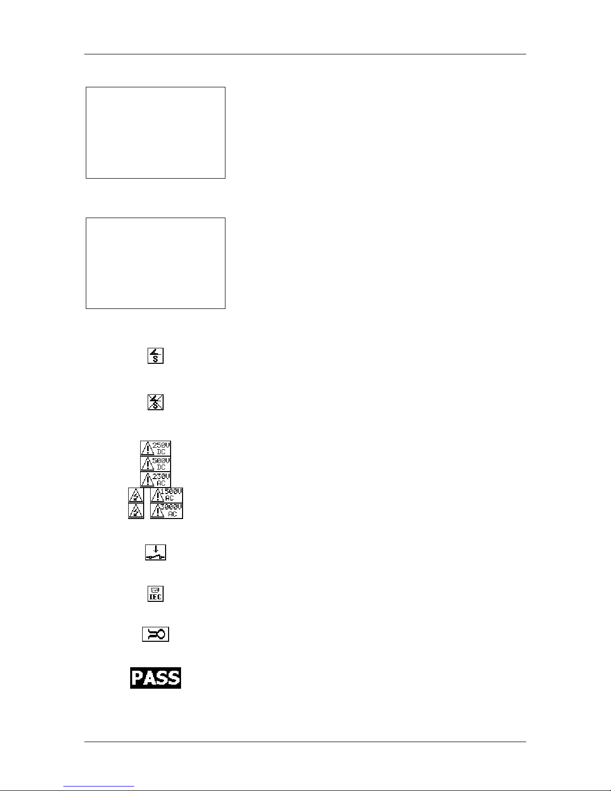
Connect earth bond test probe in this test.
Remove the earth bond clip, especially if it is connected to
any part that will begin to rotate or move when power is
applied.
Warning!
A high voltage is / will be present on the instrument output!
(Insulation test voltage, flash test voltage (MI 3305 only) or
mains voltage).
The appliance under test should be switched on (to ensure
that the complete circuit is tested).
Connect the lead to be tested to the IEC plug.
Connect current clamp adapter in this test.
Test passed.
Page 14

OmegaPATPlus / BetaPATPlus Instrument description
14
Test failed.
Some tests in the autotest sequence were skipped, but all
performed tests passed.
2.3 Dual voltage operation (UK model only)
The OmegaPATPlus / BetaPATPlus instrument will accept either a 115 V or 230 V, 50
or 60 Hz mains voltage input.
Note:
Ì The instrument will conduct a load and leakage current tests at the power up
mains voltage. Therefore, to perform a differential leakage test and touch
leakage test on 115 V appliance, the instrument must be powered up from 115 V
mains supply. When instrument is powered up from 230 V, only the 230 V test
socket is energized at 230 V during the differential leakage and touch leakage
measurements.
Page 15

OmegaPATPlus / BetaPATPlus Technical specifications
15
3 Technical specifications
3.1 Earth bond resistance
Earth bond resistance readout (10 A and 25 A)
Range Resolution Accuracy
0.00 Ω ÷ 1.99 Ω 0.01 Ω ±(5 % of reading + 3 digits)
2.00 Ω ÷ 19.99 Ω 0.01 Ω ±10 %
Earth bond resistance readout (200 mA)
Range Resolution Accuracy
0.00 Ω ÷ 1.99 Ω 0.01 Ω ±(5 % of reading + 3 digits)
2.00 Ω ÷ 9.99 Ω 0.01 Ω ± 10 %
10.0 Ω ÷ 19.9 Ω 0.1 Ω ± 10 %
Test currents............. 25 A, 10 A (± 5 %) into 100 mΩ at mains voltage of 230 V AC
200 mA into 2 Ω at mains voltage of 230 V AC
Open circuit voltage .. < 6 V AC at mains voltage of 230 V AC
Pass levels ............... 0.01 Ω ÷ 0.09 Ω, 0.10 Ω ÷ 0.90 Ω, 1.00 Ω ÷ 9.00 Ω
Test duration............. 2 s, 3 s, 5 s, 10 s, 30 s
Output....................... Class 1: S test probe connector – test socket (PE)
Test method.............. 4-wire measurement, floating to earth
3.2 Insulation resistance
Insulation resistance readout
Range Resolution Accuracy
0.000 MΩ ÷ 0.500 MΩ 0.001 MΩ ±(10 % of reading + 5 digits)
0.501 MΩ ÷ 1.999 MΩ 0.001 MΩ
2.00 MΩ ÷ 19.99 MΩ 0.01 MΩ
20.0 MΩ ÷ 199.9 MΩ 0.1 MΩ
±(5 % of reading + 3 digits)
Nominal voltages ...... 250 V DC, 500 V DC (- 0 %, + 10 %)
Measuring current..... min. 1 mA at 250 kΩ (250 V), 500 kΩ (500 V)
Short circuit current... max. 2.0 mA
Pass levels ............... 0.01 MΩ, 0.10 MΩ, 0.50 MΩ, 1.00 MΩ, 2.00 MΩ, 4.00 MΩ, 7.00
MΩ, 10.0 MΩ
Test duration............. 2 s, 3 s, 5 s, 10 s, 30 s
Output....................... Class 1: test socket
Class 2: test socket (L+N) – S test probe connector
Test method.............. floating to earth
Auto discharge after test.
Page 16

OmegaPATPlus / BetaPATPlus Technical specifications
16
3.3 Substitute leakage current
Substitute leakage current readout
Range Resolution Accuracy
0.00 mA ÷ 19.99 mA
0.01 mA
±(5 % of reading + 5 digits)
Open circuit voltage .. < 50 V AC at mains voltage of 230 V AC
Short circuit current... < 40 mA
Pass levels ............... 0.25 mA, 0.50 mA, 0.75 mA, 1.00 mA, 1.50 mA, 2.25 mA, 3.50
mA, 7.00 mA, 9.90 mA, 15.00 mA
Test duration............. 2 s, 3 s, 5 s, 10 s, 30 s
Output....................... Class 1: test socket
Class 2: test socket (L+N) – S test probe connector
Test method.............. floating to earth
Displayed current is calculated to appliance mains supply voltage.
3.4 Leakage current and apparent power
Differential leakage current readout
Range Resolution Accuracy
0.00 mA ÷ 9.99 mA
0.01 mA
±(5 % of reading + 5 digits)
Pass levels ............... 0.25 mA, 0.50 mA, 0.75 mA, 1.00 mA, 1.50 mA, 2.25 mA,
2.50 mA, 3.00 mA, 3.50 mA, 5.00 mA, 9.90 mA
Test duration............. 2 s, 3 s, 5 s, 10 s, 30 s, 60 s, 120 s, 180 s, none
Output....................... Class 1: test socket
Test method.............. Current measurement circuit according to VDE 0404-3, Appendix
A, Figure A1, IEC 60990 Figure F2
Apparent power readout
Range Resolution Accuracy
0.00 kVA ÷ 4.00 kVA
0.01 kVA
±(5 % of reading + 3 digits)
Output....................... test socket
Page 17

OmegaPATPlus / BetaPATPlus Technical specifications
17
3.5 Touch leakage current
Touch leakage current readout
Range Resolution Accuracy
0.00 mA ÷ 3.99 mA
0.01 mA
±(10 % of reading + 5 digits)
Pass levels ............... 0.25 mA, 0.50 mA, 1.00 mA, 3.50 mA
Test duration............. 2 s, 3 s, 5 s, 10 s, 30 s, 60 s, 120 s, 180 s, none
Output....................... Class 1, Class 2: test socket – S test probe connector
Test method.............. Current measurement circuit according to VDE 0404-3, Appendix
A, Figure A1, IEC 60990 Figure F2
3.6 Polarity test
Test voltage .............. < 50 V AC
Detects ..................... Pass, L-open, N-open, PE-open, L-N crossed, L-PE crossed, N-
PE crossed, L-N shorted, L-PE shorted, N-PE shorted, multiple
faults
Output....................... test socket – IEC socket
3.7 Clamp current
True RMS current readout using 1000:1 current clamp
Range Resolution Accuracy*)
0.00 mA ÷ 9.99 mA
0.01 mA
±(5 % of reading + 10
digits)
10.0 mA ÷ 99.9 mA
0.1 mA
±(5 % of reading + 5 digits)
100 mA ÷ 999 mA
1 mA
±(5 % of reading + 5 digits)
1.00 A ÷ 9.99 A
0.01 A
±(5 % of reading + 5 digits)
10.0 A ÷ 24.9 A
0.1 A
±(5 % of reading + 5 digits)
*
)
Consider accuracy of current transformer.
Pass levels ............... 0.25 mA, 0.50 mA, 0.75 mA, 1.00 mA, 1.50 mA, 2.25 mA,
2.50 mA, 3.00 mA, 3.50 mA, 5.00 mA, 9.90 mA, none
Test duration............. 2 s, 3 s, 5 s, 10 s, 30 s, 60 s, 120 s, 180 s
Input.......................... current clamp terminals
Page 18

OmegaPATPlus / BetaPATPlus Technical specifications
18
3.8 Trip-out time of portable RCD
Portable RCD trip-out time readout
Range Resolution Accuracy
0 ms ÷ 1999 ms (½×IΔN)
1 ms
0 ms ÷ 300 ms (IΔN)
1 ms
0 ms ÷ 40 ms (5×IΔN)
1 ms
±3 ms
Test currents (IΔN) ............. 10 mA, 15 mA, 30 mA
Test current multipliers ..... ½×IΔN, 1×IΔN, 5×IΔN
Test modes....................... single, autotest
Output............................... PRCD probe connector – test socket
Trip out times according to EN 61008 / EN 61009 (Aus/NZ models)
½×I
ΔN
*)
I
ΔN
5×IΔN
tΔ > 300 ms tΔ < 200 ms tΔ < 40 ms
Trip out times according BS 7671 (UK models)
½×I
ΔN
*)
I
ΔN
5×IΔN
tΔ > 1999 ms tΔ < 200 ms tΔ < 40 ms
*)
The ½×IΔN current does not trip out the RCD.
3.9 Flash test (MI 3305 – OmegaPATPlus only)
Flash current readout
Range Resolution Accuracy
0.00 - 2.50 mA 0.01 mA
±(5 % of reading + 5 digit)
Test voltage ...................... 1500 V AC, 3000 V AC
Output resistance.............. 480 kΩ@1500 V, 960 kΩ@3000 V
Limits ................................ 1.00 mA, 1.50 mA, 2.00 mA, 2.25 mA
Timer ................................ 2 s, 3 s, 5 s, 10 s, 30 s
Output............................... Class 1: test socket
Class 2: test socket (L+N) – flash probe connector
3.10 General data
Rated supply voltage .........................230 VAC / 115 VAC (±10 %, 50 or 60 Hz)
Max. power consumption.................. 150 VA (earth bond 25 A short-circuit, without
tested appliance)
Maximum appliance current...............16 A
Overvoltage category.........................Cat II / 300 V
Protection classification .....................I
Pollution degree.................................2
Page 19

OmegaPATPlus / BetaPATPlus Technical specifications
19
Degree of protection ..........................IP 50 (closed and locked cover)
Case ..................................................shock proof plastic / portable
Display...............................................240*128 dots graphic matrix display with backlight
Dimensions (w×h×d)..........................33.5 cm × 16.0 cm × 33.5 cm
Weight (with standard accessories) ...MI 3305 OmegaPAT Plus: 8.95 kg
MI 3304 BetaPAT Plus: 7.85 kg
Memory..............................................6500 memory locations
RS232 interfaces .............................. 1200 bps ÷ 115200 bps, 1 start bit, 8 data bits,
1 stop bit
RS232 connectors .............................9-pin subminiature type D, female
Label printer connector.......................6-pin DIN connector, female
USB interface ....................................1200 bps ÷ 115200 bps
USB connector...................................type B
Reference conditions
Reference temperature range............5 °C ÷ 35 °C
Reference humidity range..................35 % ÷ 65 % RH
Operation conditions
Working temperature range ...............-10 °C ÷ +50 °C
Maximum relative humidity ................85 % RH (0 °C ÷ 40 °C), non-condensing
Storage conditions
Temperature range ............................-10 °C ÷ +60 °C
Maximum relative humidity ................90 % RH (-10 °C ÷ +40 °C)
80 % RH (40 °C ÷ 60 °C)
Accuracies apply for 1 year in reference conditions. Temperature coefficient outside
these limits is 0.2 % of measured value per °C, and 1 digit.
Fuses
Instrument protection .........................2 x T16 A / 250 V, 6.3 × 32 mm
Protection pre-tests
Ì External voltage between L and PE, N and PE or L and N (DC and AC)
Ì Excessive leakage between L and PE or N and PE
Ì Short circuit or very low resistance between L and N
Connectivity (fuse) pre-test
Ì Appliance not switched on or too high resistance between L and N
Maximum resistance for connectivity pre-test.................................. 30 kΩ
Page 20
OmegaPATPlus / BetaPATPlus Main menu and test modes
20
4 Main menu and test modes
The OmegaPATPlus / BetaPATPlus instrument has a user-friendly manipulation. By
pressing only a few keys most of the actions can be done. The menu tree of the
instrument has been designed to be simple to understand and easy to operate.
The instrument can test appliances in four different modes:
Ì single test mode,
Ì three autotest modes.
After the instrument is switched on, the last menu used will be displayed.
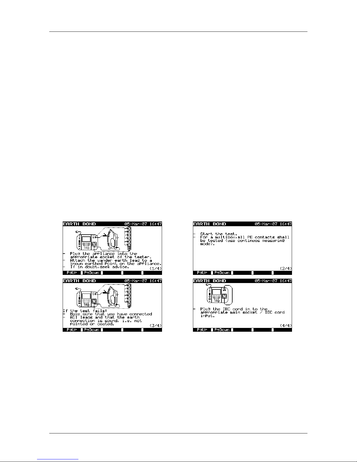
4.1 Help menus
The measurement help menus are available in single and autotest modes. Help menu
contain schematic diagrams for illustration of proper connection of appliance under test
to the PAT testing instrument.
4.1.1 How to enter help menu
After entering the selected measurement and before pressing START, press the F2
function key in order to view help menu.
Example of help menus
Use F1 and F2 function keys to see the next / previous page (if available).
Press ESC key to return to the last test / measurement menu.
Page 21

OmegaPATPlus / BetaPATPlus Main menu and test modes
21
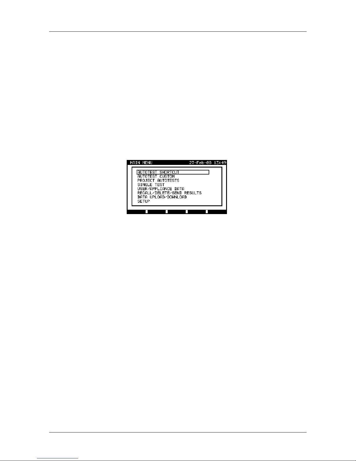
4.2 Main menu
From the Main menu all the instrument functions can be selected.
Main menu
Select the function you want to perform by using ¿ and À cursor keys and press
ENTER key to confirm. To return to the Main menu press the ESC key.
Note:
Ì The ESC key has need to be pressed more than once to return to Main menu
from any submenu or selected function.
4.3 Autotest shortcut menu
In this menu there are all the most popular pre-defined autotest sequences that can be
selected and performed (shown in appendix B and C of this manual). When an autotest
sequence has been completed, the measurement results can be stored into instrument
flash memory or sent to the printer or PC for further processing.
Aus/NZ model
UK model
Autotest shortcut menu examples
See chapter
7 Autotest sequences for detailed description of this test mode.
4.4 Autotest custom menu
It might happen that none of the preset autotest shortcut sequences corresponds with a
particular appliance’ test requirements. For this reason, an autotest procedure can be
created in the autotest custom menu. In this menu the autotest results can be stored
into the instrument flash memory or sent to the PC for further purposes (as well test
reports can be printed out, etc.).
Page 22
OmegaPATPlus / BetaPATPlus Main menu and test modes
22
Autotest custom menu
See chapter 7 Autotest sequences for detailed description about this test mode.
4.5 Project autotests menu
The Project autotest is a tool that simplifies and speeds up repeated (periodic) testing of
appliances. The main idea is to re-use known and stored data about the appliance
under test.
Aus/NZ model
UK model
Project autotest menu examples
See chapter
7.3 Project autotests for detailed description about this autotest mode.
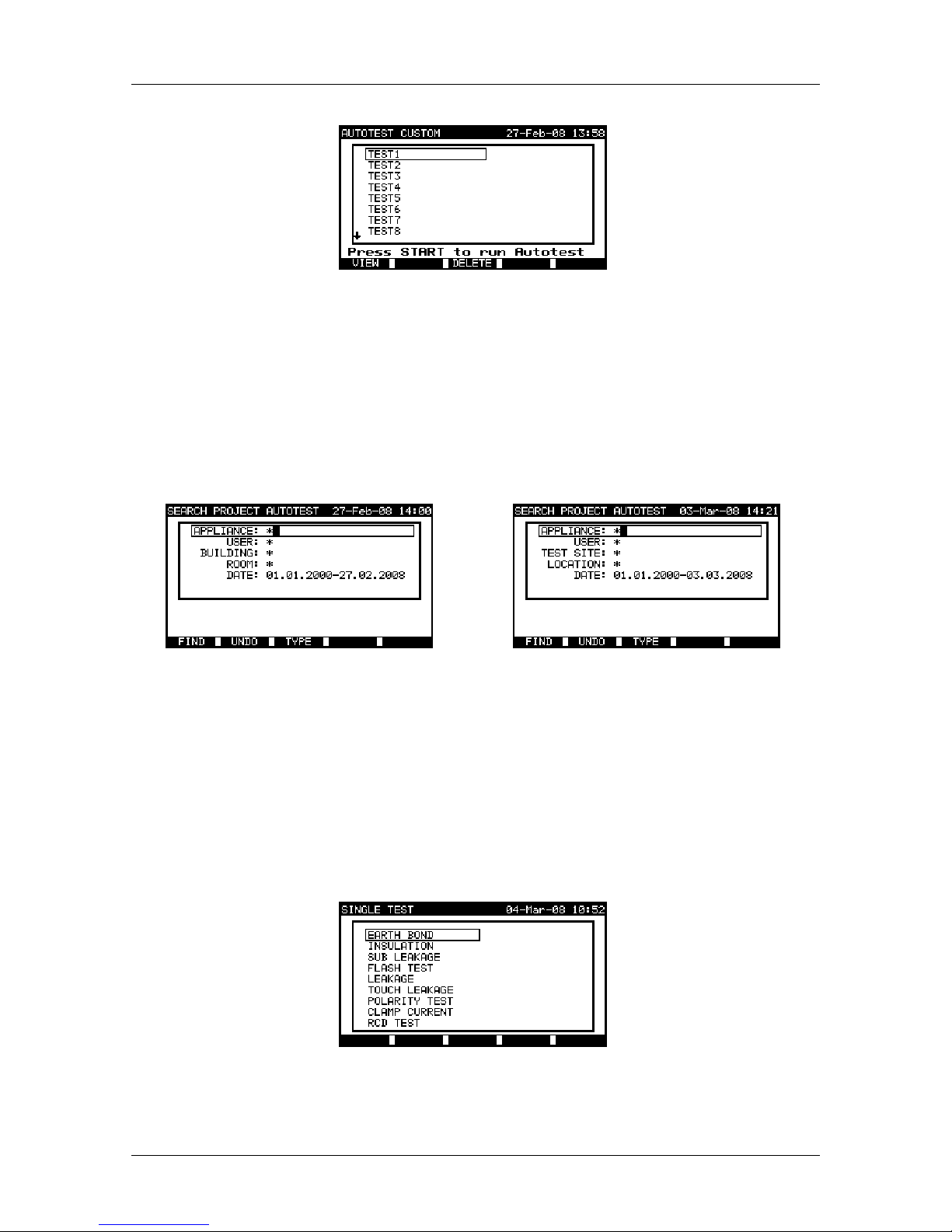
4.6 Single test menu
In single test menu individual tests can be performed. Note: that measurement results
performed in this mode cannot be stored.
Single test menu
See chapter
5 Single test mode for detailed description about the single test mode.
Page 23
OmegaPATPlus / BetaPATPlus Main menu and test modes
23
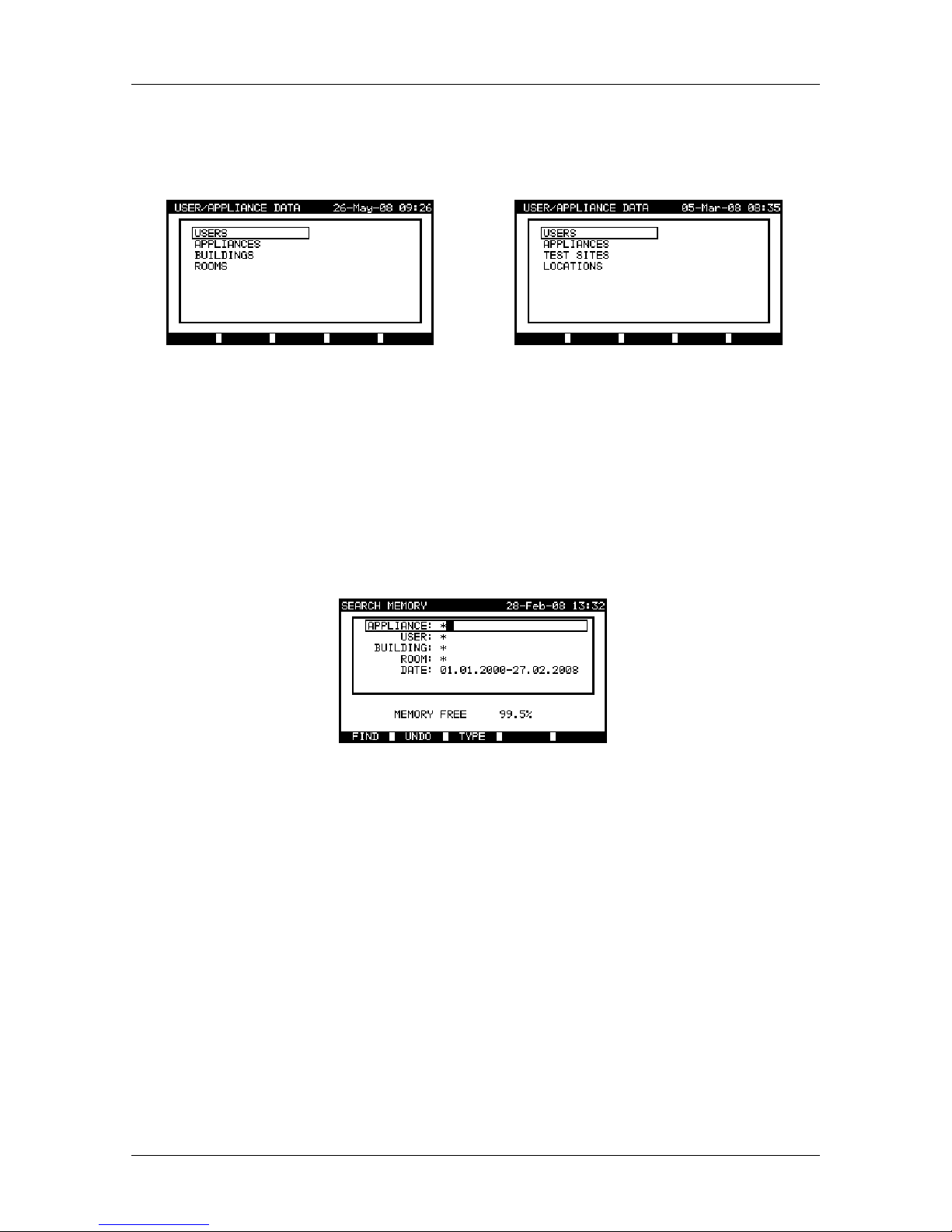
4.7 User / appliance data menu
In this menu lists of user and appliance data default names can be edited. An
alternative is to upload the lists from PC.
Aus/ NZ model
UK model
Users / appliance data main menu
See chapter 9.1 User / appliance data menu for detailed description about this
functionality.
4.8 Recall / delete / send results menu
Manipulation with stored data is allowed in this menu. Stored results can be recalled
according to appliance name and date, deleted or send to PC or printers.
Recall results menu
See chapters 8.2 Recalling results, 8.3 Deleting results and 8.4 Downloading and
printing results for more information.
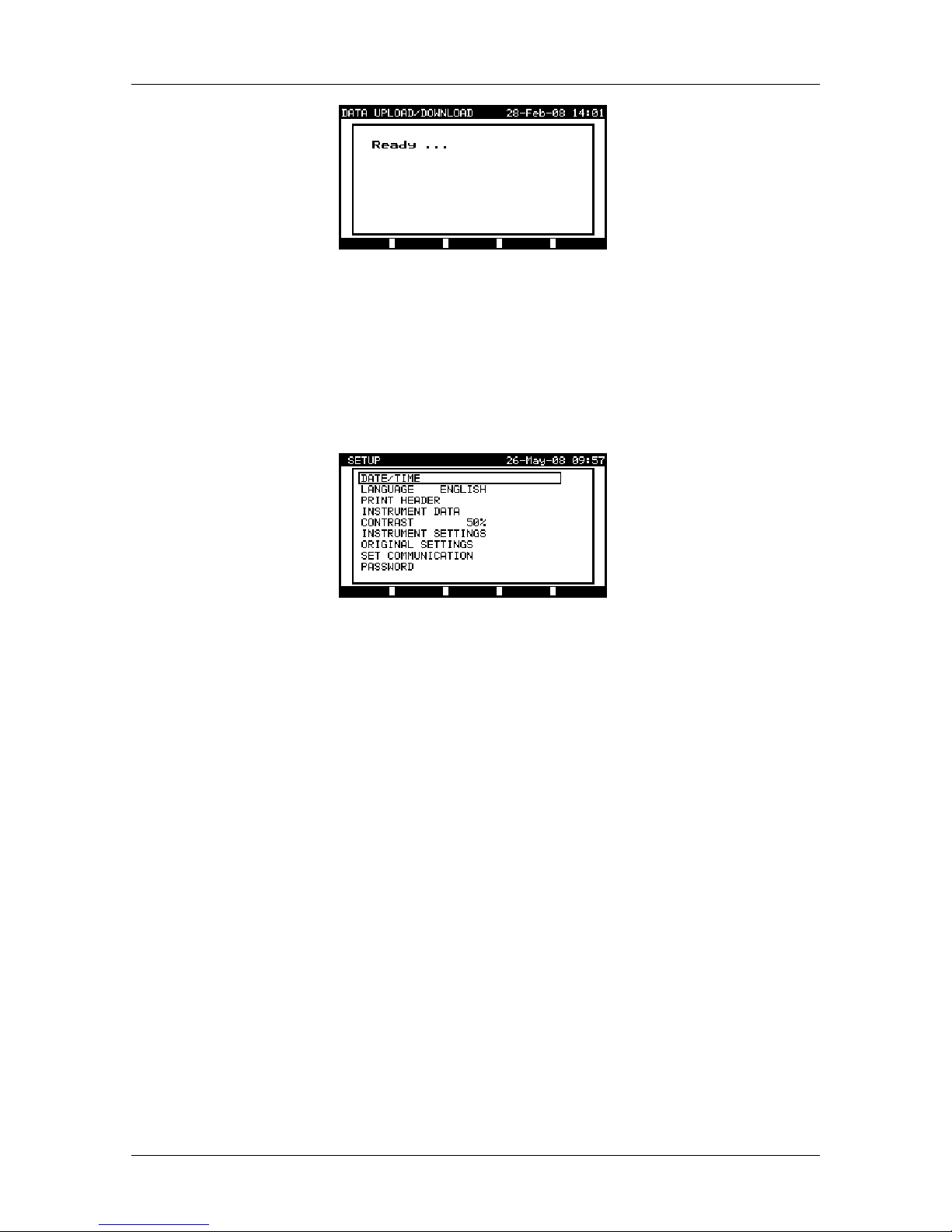
4.9 Data upload / download menu
In this menu it is possible to upload different data from PC to the instrument:
Ì stored test results and data (results, parameters, notes)
Ì list of default appliance and test site names.
The data to be uploaded are selected in the PCSW package.
Page 24
OmegaPATPlus / BetaPATPlus Main menu and test modes
24
Upload of test data menu
See chapter 9.2 Data upload / download for detailed description about
uploading/downloading data from PC.
4.10 Setup menu
In this menu general instrument parameters can be set.
Setup menu
See chapter 9.3 Setup menu for detailed description.
Page 25
OmegaPATPlus / BetaPATPlus Single test mode
25
5 Single test mode
In single test mode, individual tests can be performed. This is especially helpful when
the test engineer suspects that one or more faults are present in the appliance under
test.
Note:
Ì Test results cannot be saved in this mode!
5.1 How to perform measurements in single test mode
Select Single test in Main menu by using ¿ and À cursor keys and press ENTER key
to confirm the selection. The Single test menu is displayed.
Single test menu
By using ¿ and À cursor keys select the measurement you want to perform and press
ENTER key to confirm the selection. To return to the Single test menu press ESC key.
Selected test measurement parameters are detailed in the top right corner of the
display. These parameters can be edited by pressing the F1 button. In general the
following parameters can be set:
Ì output test voltage/current,
Ì pass level,
Ì measurement duration.
Once the test parameters have been set, the settings are saved until new changes are
made or the instrument is reset to the default configuration.
Note:
Ì To keep new settings in the case of a power failure, return to main menu or press
SAVE before turning the power off.
Page 26
OmegaPATPlus / BetaPATPlus Measurements
26
6 Measurements
6.1 Earth bond resistance
This test ensures that the connections between the protective conductor terminal in the
mains plug of the appliance and any accessible conductive parts of the appliance (metal
housing) are satisfactory and of sufficiently low resistance. This test has to be
performed on Class 1 (earthed) appliances.
A high current is normally used to check that the connections will operate correctly
under fault conditions. In some sensitive electronic equipment such as computers and
other information technology equipment that contain a functional earthing arrangement,
a high current test can damage the equipment. In this situation, a 200 mA test current is
used to prevent damage to the internal components of the appliance.
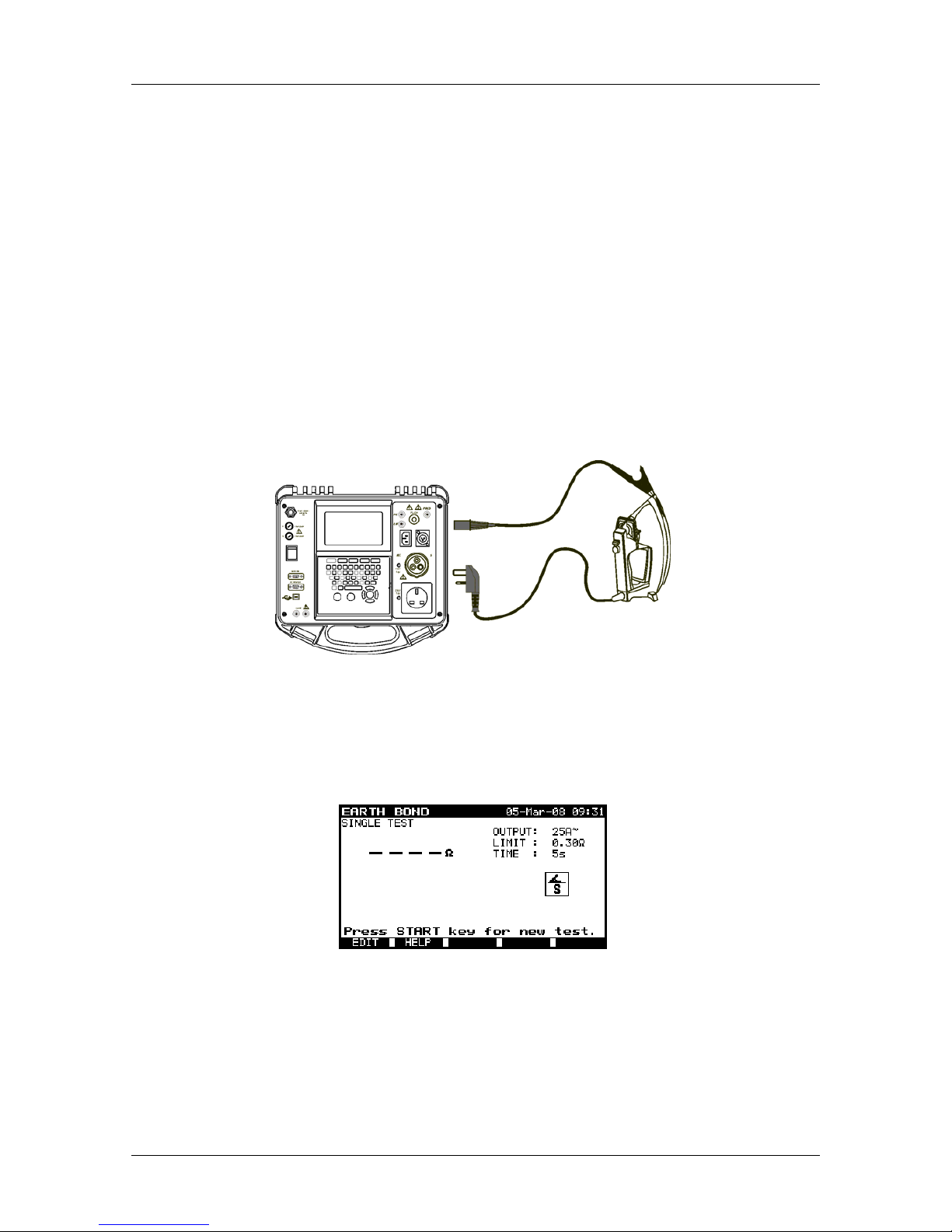
The instrument measures the resistance between test socket‘s PE terminal and earth
bond clip (connected to socket S of the appliance).
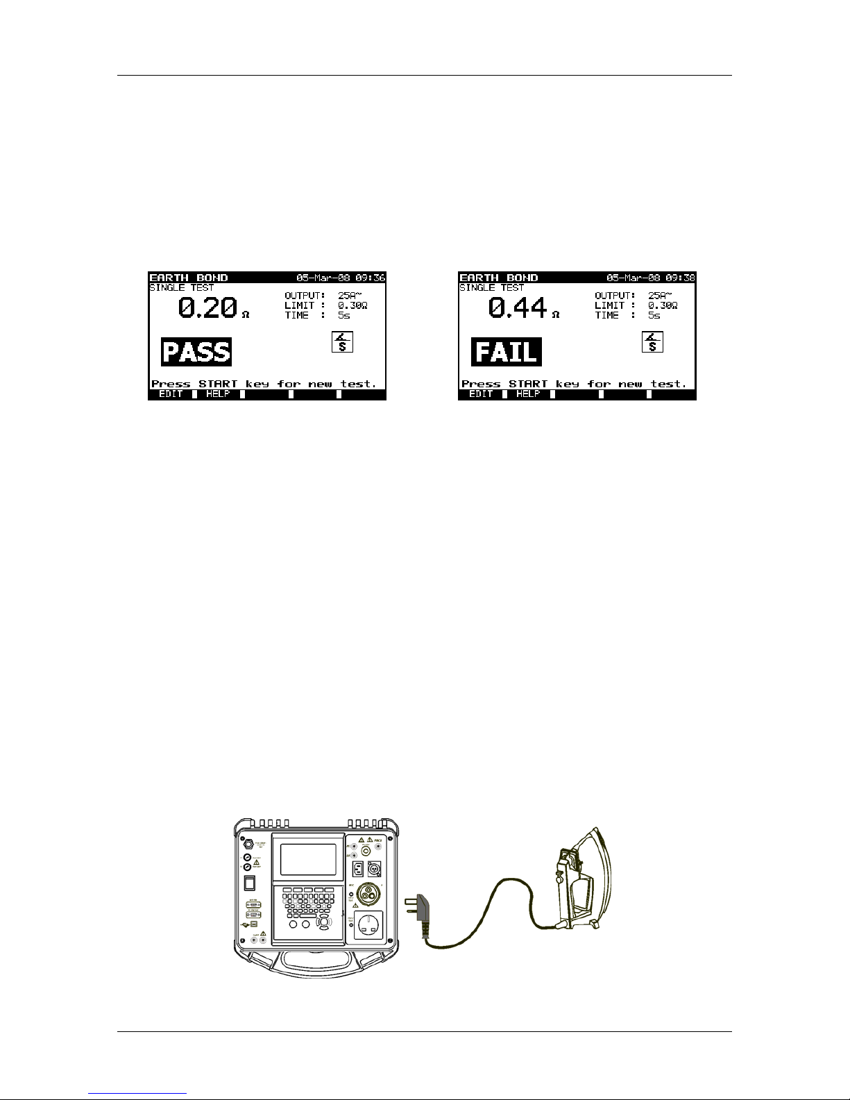
Measurement of earth bond resistance of class I appliance
6.1.1 How to perform earth bond resistance measurement
From the Main menu, select Single test and then select Earth bond by using ¿ and À
cursor keys and press ENTER key to confirm. Earth bond menu is displayed.
Earth bond menu
Measurement parameters are detailed in the top right corner of the display. The
following parameters can be adjusted:
Ì nominal test current,
Ì high limit resistance value,
Ì measurement duration.
Page 27
OmegaPATPlus / BetaPATPlus Measurements
27
To edit parameters, press the F1 function key first. Use ¿ and À cursor keys to select
the parameter you want to edit. By using ½ and ¾ cursor keys adjust the selected
parameter. Press F1 function key again to confirm settings.
Once the settings have been set, press the START key to perform measurement.
The measurement can be aborted by pressing STOP key at any time. The actual result
is shown on the display during measurement. After the measurement time period has
elapsed the last measured value is displayed, and PASS or FAIL indication appears on
the display (based on the high resistance limit defined in the settings).
Examples of earth bond resistance measurement results
Press the START key to repeat the test or press ESC key to return to the Single test
menu.
Note:
Ì Consider any displayed warning before starting measurement!
6.2 Insulation resistance
The insulation resistance test checks the resistance between live conductors and
earthed (or isolated) accessible metal parts of an appliance. This test can disclose faults
caused by pollution, moisture, deterioration of insulation metal etc. The capacitive part
of leakage currents is not measured because of the DC test voltage.
6.2.1 Insulation resistance on class I appliances
The instrument measures the insulation resistance between:
Ì (L+N) and PE of the relevant test socket,
Ì LN and PE test sockets.
Measurement of insulation resistance of class I appliance
Page 28
OmegaPATPlus / BetaPATPlus Measurements
28
Measurement of insulation resistance of fixed installed appliances of Class I
6.2.2 Insulation resistance on class II appliances
The instrument measures the insulation resistance between:
Ì (L+N) of the relevant test socket and S test terminals,
Ì LN and S test sockets.
Measurement of insulation resistance of class II appliance
Measurement of insulation resistance of accessible isolated conductive parts of fixed
installed appliances
Page 29

OmegaPATPlus / BetaPATPlus Measurements
29
6.2.3 How to perform single insulation resistance measurement
From the Main menu, select Single test and then select Insulation by using ¿ and À
cursor keys and press ENTER key to confirm. Insulation menu is displayed.
Insulation menu
Measurement parameters are detailed in the top right corner of the display. The
following parameters can be adjusted in this measurement:
Ì nominal test voltage,
Ì low limit resistance value,
Ì measurement duration.
To edit parameters, press the F1 function key first. Use ¿ and À cursor keys to select
the parameter you want to edit. By using ½ and ¾ cursor keys adjust the selected
parameter. Press F1 function key again to confirm confirm the selected settings.
Press the START key to perform a measurement.
The measurement can be aborted by pressing STOP key at any time. The actual result
is shown on the display during the measurement. After the measurement time has
elapsed the last measured value is displayed, and PASS or FAIL indication appears on
the display (based on the low limit resistance value).
Examples of insulation resistance measurement results
Press START key to repeat the test or press ESC key to return to the Single test
menu.
Notes:
Ì The appliance under test should be de-energized before the measurement!
Ì Consider any warning on the display before starting the measurement!
Ì Do not touch the appliance under test during the measurement or before it is fully
discharged! The message »Discharging…« will be displayed while the voltage on
the appliance under test is higher than 20 V!
Page 30

OmegaPATPlus / BetaPATPlus Measurements
30
Ì Do not disconnect the appliance under test from the instrument during the
measurement or before it is automatically discharged!
6.3 Substitute leakage current
Leakage currents between live conductors and isolated accessible metal parts (housing,
screws, handles etc.) are checked with this test. Capacitive leakage paths are included
in the result too. The test measures the current flowing at a test voltage of 40 VAC and
the result is scaled to the value of a nominal mains supply voltage of 230 VAC.
6.3.1 Substitute leakage current on class I appliances
The instrument measures the substitute leakage current between:
Ì main test socket (L+N) and PE test terminals,
Ì LN and PE test sockets.
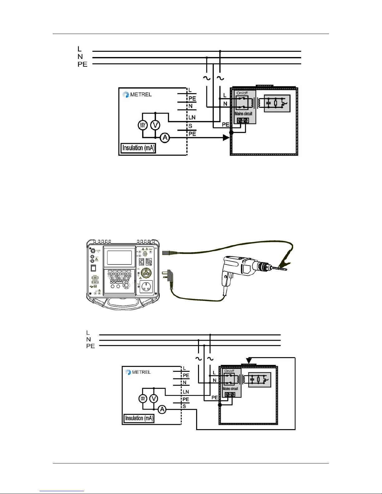
Measurement of substitute leakage current of class I appliance
Measurement of substitute leakage current of fixed installed appliances of class I
6.3.2 Substitute leakage current on class II appliances
The instrument measures leakage current between:
Ì main test socket (L+N) and S test terminals,
Ì LN and S test sockets.
Page 31

OmegaPATPlus / BetaPATPlus Measurements
31
Measurement of substitute leakage current of class II appliance
Measurement of substitute leakage of accessible isolated conductive parts of fixed
installed appliances
6.3.3 How to perform single substitute leakage current measurement
From the Main menu, select Single test and then select Sub leakage by using ¿ and
À cursor keys and press ENTER key to confirm. Sub leakage menu is displayed.
Sub leakage menu
Measurement parameters are detailed in the top right corner of the display. The
following parameters can be adjusted in this measurement:
Ì high limit leakage value,
Ì measurement duration.
Page 32

OmegaPATPlus / BetaPATPlus Measurements
32
To edit parameters, press the F1 function key first. Use ¿ and À cursor keys to select
the parameter you want to edit. By using ½ and ¾ cursor keys adjust the selected
parameter. Press F1 function key again to confirm the selected settings.
Press the START key to perform measurement.
The measurement can be aborted by pressing STOP key at any time. The actual result
is shown on the display during the measurement. After measurement time has elapsed
the last measured value is displayed, and PASS or FAIL indication appears on the
display (based on the high limit leakage value).
Examples of substitute leakage current measurement results
Press START key to repeat the test or press ESC key to return to the Single test
menu.
Notes:
Ì Consider any displayed warning before starting measurement!
Ì Substitute leakage current may differ substantially from that of conventional
leakage current test because of the way the test is performed. For example, the
difference in both leakage measurements will be affected by the presence of
neutral to earth noise suppression capacitors.
6.4 Leakage current and power
The purpose of this test is to determine the sum of all leakages flowing from the live
conductor to the earth. Because the differential method for determining leakage current
is used the full and true appliance leakage current is always measured, even when
parallel current paths to ground exist in the appliance.
The apparent power of the appliance is also measured at the same time as leakage
current. By checking the power an efficient functional test can be performed.
Measuring of leakage current and power
Page 33

OmegaPATPlus / BetaPATPlus Measurements
33
6.4.1 How to perform single leakage current measurement
From the Main menu, select Single test and then select Leakage by using ¿ and À
cursor keys and press ENTER key to confirm. Leakage menu is displayed.
Leakage menu
Measurement parameters are detailed in the upper right corner of the display. The
following parameters can be adjusted for this measurement:
Ì high limit leakage value,
Ì measurement duration.
To edit parameters press F1 function key first. Use ¿ and À cursor keys to select the
parameter you want to edit. By using ½ and ¾ cursor keys adjust the selected
parameter. Press F1 function key again to confirm the selected settings.
Press the START key to perform a measurement.
The measurement can be aborted by pressing STOP key at any time. Actual result is
shown on the display during measurement. After measurement time period has elapsed
the last measured value is displayed, and PASS or FAIL indication appears on the
display (based on the high limit leakage value).
Examples of leakage current and apparent power measurement results
Press START key to repeat the test or press ESC key to return to the Single test
menu.
Notes:
Ì During the test, a mains voltage is connected to the appliance. If appliance
contains moving parts, make sure that it is safely mounted or protected to
prevent possible danger to the operator or damage to the appliance or
surrounding environment!
Ì Consider any displayed warning before starting measurement!
Page 34

OmegaPATPlus / BetaPATPlus Measurements
34
6.5 Touch leakage current
This test determines the current that would flow if a person touches the appliance.
Measurement is based on a human body model with resistance of 2 kΩ. Both AC and
DC components of touch leakage current are detected.
The instrument measures the leakage current flowing through the S probe into earth.
The appliance under test can be powered from the mains test socket or directly from the
installation (fixed installed equipment).
Measurement of touch leakage current
Measurement of touch leakage current on a fixed installed appliance
6.5.1 How to perform single touch leakage current measurement
From the Main menu, select Single test and then select Touch leakage by using ¿
and À cursor keys and press ENTER key to confirm. Touch leakage menu is
displayed.
Touch leakage menu
Page 35

OmegaPATPlus / BetaPATPlus Measurements
35
Measurement parameters are detailed in the top right corner of the display. The
following parameters can be adjusted in this measurement:
Ì high limit leakage value,
Ì measurement duration.
To edit parameters press F1 function key first. Use ¿ and À cursor keys to select the
parameter you want to edit. By using ½ and ¾ cursor keys adjust the selected
parameter. Press F1 function key again to confirm the selected settings.
Press the START key to perform a measurement.
The measurement can be aborted by pressing STOP key at any time. The actual result
is shown on the display during the measurement. After the measurement time period
has elapsed the last measured value is displayed, and PASS or FAIL indication appears
on the display (based on the high limit leakage value).
Examples of touch leakage current measurement results
Press START key to repeat the test or press ESC key to return to the Single test
menu.
Notes:
Ì During the test, a mains voltage is connected to the appliance. If appliance
contains moving parts, make sure that it is safely mounted or protected to
prevent possible danger to the operator or damage to the appliance or
surrounding environment!
Ì Consider any displayed warning before starting measurement!
6.6 Polarity test
This test checks the polarity of a mains supply cable. The following faults can be
detected: L open, N open, PE open, L-N crossed, L-PE crossed, N-PE crossed, L-N
shorted, L-PE shorted, N-PE shorted, multiple faults.
Page 36

OmegaPATPlus / BetaPATPlus Measurements
36
Polarity test of IEC cord
6.6.1 How to perform the measurement
From the Main menu, select Single test and then select Polarity test by using ¿ and
À cursor keys and press ENTER key to confirm. Polarity test menu is displayed.
Polarity test menu
Connect the lead between the IEC port of the PAT tester and the mains test socket.
Press START key to perform test.
After performing the test PASS or FAIL indication appears on the display. In the case of
a FAIL result the detected fault is displayed.
Examples of polarity test results
Press START key to repeat the test or press ESC key to return to the Single test
menu.
Note:
Ì Consider any displayed warning before starting test!
Ì This test is only for use on IEC cables and extension cables.
Ì When testing extension cables, a route back to the IEC port of the instrument
must be made otherwise the test will fail.
Page 37

OmegaPATPlus / BetaPATPlus Measurements
37
6.7 TRMS current measurement using clamp current
adapter
This function enables the measurement of AC currents in a wide range from 1 mA up to
25 A. Typical applications are:
Ì measuring leakage currents through PE conductor in permanently installed
appliances,
Ì measuring load currents through L or N conductor in permanently installed
appliances,
Ì measuring leakage currents through parallel current paths, etc.
6.7.1 How to perform TRMS current measurement using clamp
current adapter
In order to measure a true RMS current connect the current clamp to the instrument
CLAMP connector first.
Connecting current clamp to the BetaPAT instrument
From the Main menu, select Single test and then select Clamp current by using ¿
and À cursor keys and press ENTER key to confirm. Clamp current menu is
displayed.
Clamp current menu
Measurement parameters are detailed in the top right corner of the display. The
following parameters can be adjusted in this measurement:
Ì high limit current value,
Ì measurement duration.
Page 38

OmegaPATPlus / BetaPATPlus Measurements
38
To edit parameters press F1 function key first. Use ¿ and À cursor keys to select the
parameter you want to edit. By using ½ and ¾ cursor keys adjust the selected
parameter. Press F1 function key again to confirm the selected settings.
Press the START key to perform a measurement.
The measurement can be aborted by pressing STOP key at any time. The actual result
is shown on the display during the measurement. After the measurement time period
has elapsed the last measured value is displayed, and PASS or FAIL indication appears
on the display (based on the high limit current value).
Examples of clamp current measurement results
Press START key to repeat the measurement or press ESC key to return to the Single
test menu.
Notes:
Ì Consider any displayed warning before starting measurement!
Ì When measuring leakages neighbor magnetic fields and capacitive coupling
(especially from the L and N conductors) can disturb the results. It is
recommended that the clamp is as close as possible to the grounded surface and
away from wires and other objects under voltage or carrying current
Ì Use test clamp supplied by METREL or other with similar characteristics (current
output, ratio 1000:1, appropriate measurement range; consider error of test
clamp when evaluating measured results)!
6.8 RCD test
The purpose of this test is to ensure the proper operation of residual current devices
built into an appliances and portable residual current devices.
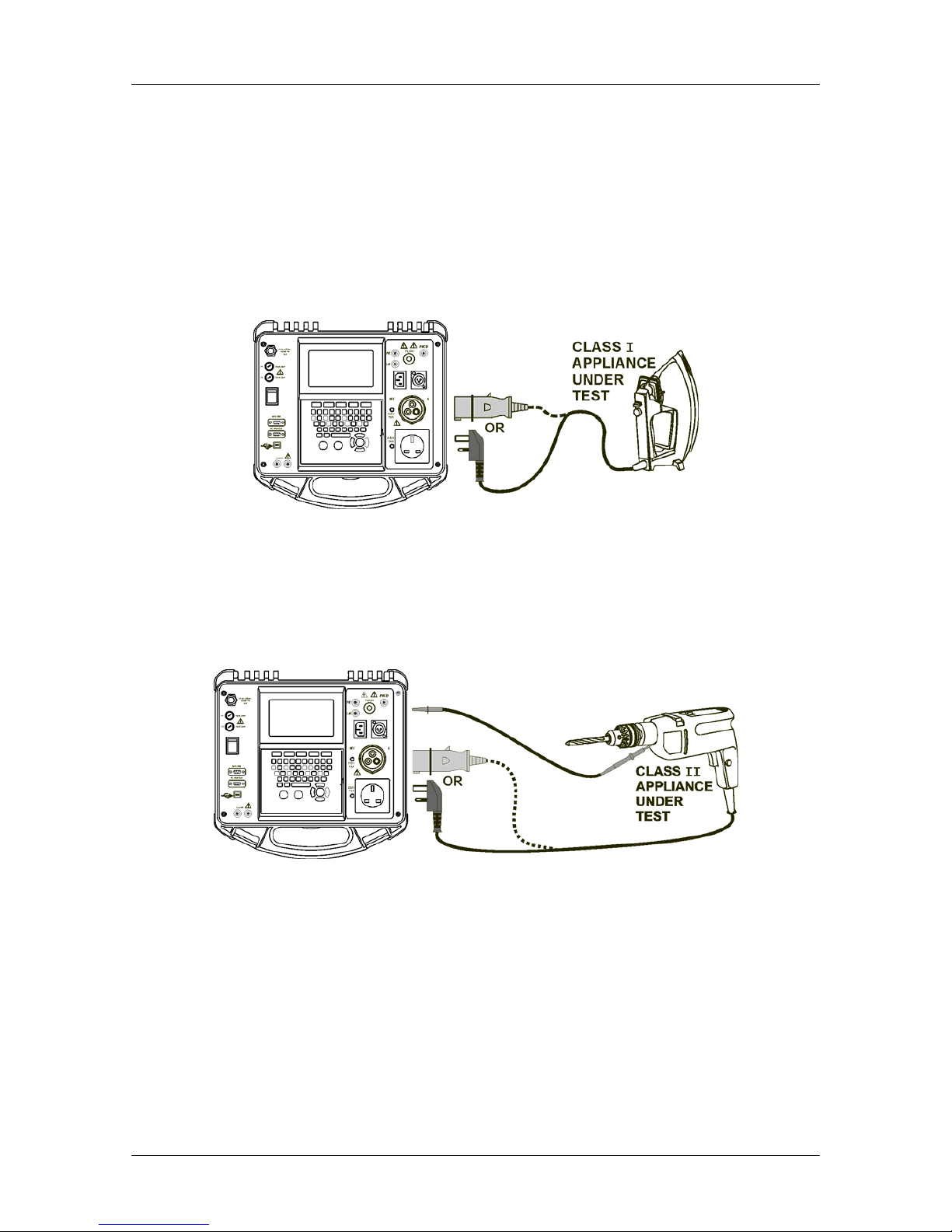
6.8.1 RCD test on appliances
For the RCD test the appliance must be plugged in the main test socket and the PRCD
test probe must be used. Depending on the type of PRCD, it may be necessary to
manually switch the PRCD on.
During the test the instrument simulates a fault current between the RCDs L (line)
output and the instruments PRCD socket.
Page 39
OmegaPATPlus / BetaPATPlus Measurements
39
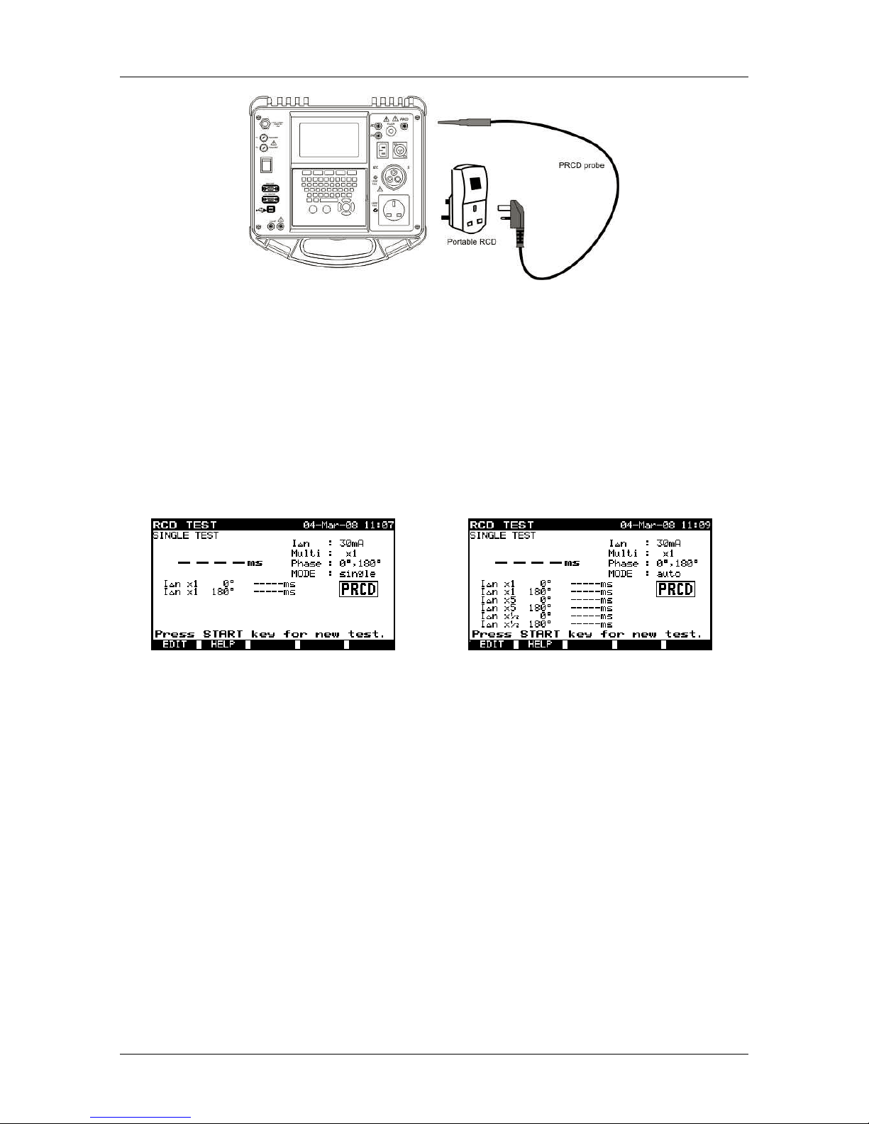
Testing of portable RCD
First connect portable RCD unit into the test socket. Then connect PRCD test probe to
the portable RCD unit and the other end of PRCD probe to the PRCD socket of the
instrument.
6.8.2 How to perform an RCD test
From the Main menu, select Single test and then select RCD test by using ¿ and À
cursor keys and press ENTER key to confirm. RCD menu is displayed.
RCD single test menu
RCD autotest menu
Measurement parameters are detailed in the top right corner of the display. The
following parameters can be adjusted in this measurement:
Ì nominal test current value,
Ì test current size (multiplier),
Ì test current starting polarity,
Ì test mode.
To edit the parameters, press the F1 function key first. Use ¿ and À cursor keys to
select the parameter you want to edit. By using ½ and ¾ cursor keys adjust the selected
parameter. Press F1 function key again to confirm the selection.
Nominal test current I
Δ
N
The nominal test current can be set to 10mA, 15mA and 30mA. These are the typical
values for portable RCDs.
Page 40

OmegaPATPlus / BetaPATPlus Measurements
40
Test current size (multiplier)
The RCD functional standards define maximal allowed trip out times (see chapter 3.8
Technical specifications) at current values I
ΔN
and 5×IΔN. At ½×IΔN the RCD must not
trip out.
Starting polarity
The RCD test must be performed at two different residual current starting polarities (0º
and 180º). This is neccessary because the sensitivity of some RCDs depends on the
polarity of the residual current.
RCD test current starting polarities
Test mode
In the RCD single test mode the RCD operation is checked at the user-defined test
conditions. The purpose of this test is to performmake a fast RCD operation check.
In the RCD autotest the RCD operation is checked at all current multipliers. The
purpose of this test is to perform a complete test of the RCD operation.
6.8.3 How to perform RCD single test
Enter RCD single test menu as described in chapter 6.8.2 How to perform an RCD
test.
RCD single test menu
For the RCD test the appliance must be plugged in the instrument's main test socket
and the PRCD test probe must be connected.
Step 1
Instrument displays the message »Press START key for new test.«.
After setting the parameters, press the START key to apply a voltage to the main
test socket.
Step 2
The instrument displays the message »RCD ON and press START key to
proceed«.
Check that the RCD is switched ON (most of portable RCDs must be manually
switched on after they plugged in) and the PRCD test probe is connected
Page 41
OmegaPATPlus / BetaPATPlus Measurements
41
properly between the PRCD socket of the instrument and the mains connections
of the RCD (as illustrated in chapter 6.8.1 RCD test on appliance).
The conditions for performing the test are fulfilled when the displayed voltage
indication shows that a voltage is applied.
Press the START key to begin the 1st test (IΔN, 0º). The measurement normally
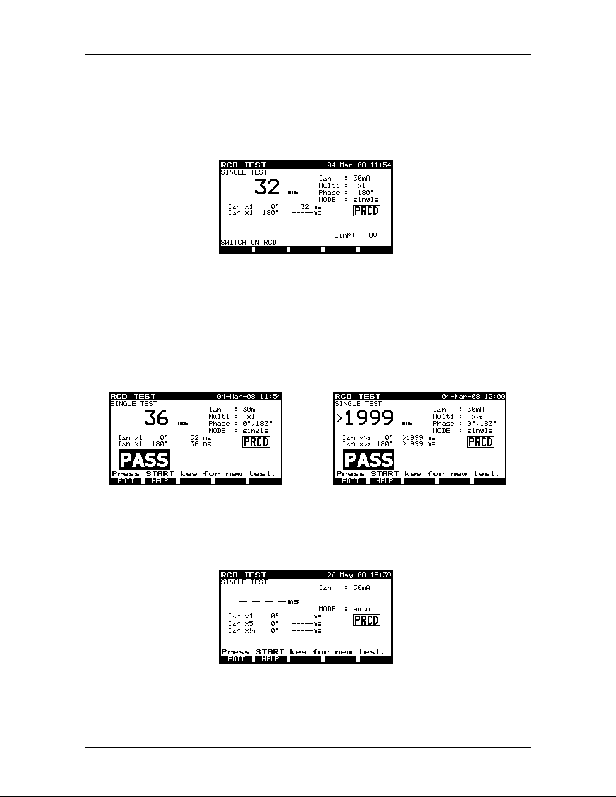
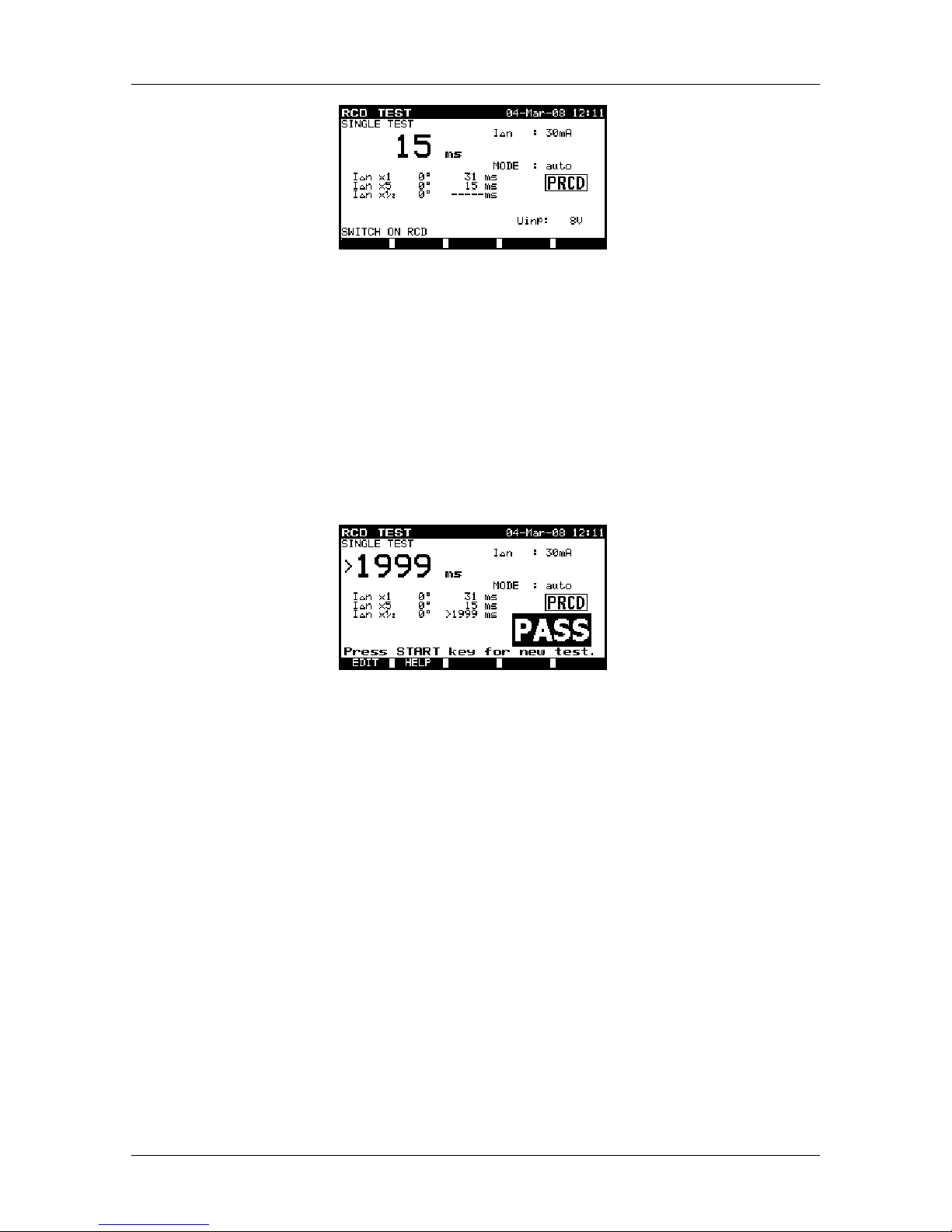
trips an RCD within the allowed time period. The following menu is displayed:
Example of RCD test result
Step 3
Reset the RCD.
The instrument automatically proceeds with the 2nd test (IΔN x1, 180º).
The test passes if the RCD trips inside the predefined limits on both polarities. If this is
the case, a PASS indication will be displayed.
The measurement can be aborted at any time by pressing ESC key.
Examples of RCD single test results
6.8.4 How to perform RCD auto test
Enter RCD auto test menu as described in chapter 6.8.2 How to perform an RCD test.
RCD auto test menu
For the RCD test the appliance must be plugged in the instrument's main test socket
and the PRCD test probe must be connected.
Page 42

OmegaPATPlus / BetaPATPlus Measurements
42
Step 1
Instrument displays the message »Press START key for new test.«.
After setting the parameters, press the START key to apply a voltage to the main
test socket.
Step 2
The instrument displays the message »RCD ON and press START key to
proceed.«.
Check that the RCD is switched ON (most of portable RCDs must be manually
switched on after they plugged in) and the PRCD test probe is connected
properly between the PRCD socket of the instrument and the mains connections
of the RCD (as illustrated in chapter 6.8.1 RCD test on appliance).
The conditions for performing the test are fulfilled when the displayed voltage
indication shows that a voltage is applied.
The autotest sequence starts to run as described in the following steps.
Step 3
Trip-out time measurement with the following measurement parameters:
Ì test current of IΔN,
Ì test current started with the positive half-wave (from 00).
The measurement normally trips an RCD within the allowed time period. The
following menu is displayed:
RCD auto test result example (I
ΔN
, 0
0
)
After resetting the RCD, the autotest sequence automatically proceeds with the
next step.
Step 4
Trip-out time measurement with the following measurement parameters:
Ì test current of 5×IΔN,
Ì test current started with the positive half-wave (from 00).
The measurement normally trips an RCD within the allowed time period. The
following menu is displayed:
Page 43
OmegaPATPlus / BetaPATPlus Measurements
43
RCD auto test result example (5×I
ΔN
, 0
0
)
After resetting the RCD, the autotest sequence automatically proceeds with the
next step.
Step 5
Trip-out time measurement with the following measurement parameters:
Ì test current of ½×IΔN,
Ì test current started with the positive half-wave (from 00).
Measurement does NOT normally trip an RCD. The following menu is displayed
after an autotest sequence has been completed:
RCD autotest results
The test passes if the RCD:
Ì does not trip out at ½×IΔN tests,
Ì trips within the predefined limits at I
ΔN
, and 5×IΔN tests and a PASS indication is
displayed.
If all of these conditions have been met, a PASS indication is dispayed.
The measurement procedure can be aborted at any time by pressing ESC key.
Notes:
Ì Consider any displayed warning before starting measurement!
Ì For appliances with integrated RCD the housing must be opened to access the
RCD’s L output terminal (this should only be performed by a competent
engineer).
Ì Mains voltage is applied to the device under test. Do not touch the equipment
under test or the test leads during the test.
Page 44
OmegaPATPlus / BetaPATPlus Measurements
44
6.9 Flash test (MI 3305 – OmegaPATPlus only)
The purpose of this test is to ensure that the insulation material of the appliance can
withstand high voltage transients and short overvoltages.
6.9.1 Flash test on class I appliances
For Class I appliances, a test voltage of 1.5 kVAC is applied between main test socket
(L+N) and PE test terminals.
Flash test on Class I appliance
6.9.2 Flash test of class II appliances
For Class II appliances, a test voltage of 3 kVAC is applied between main test socket
(L+N) and FLASH test terminals.
Flash test on Class II appliance
6.9.3 How to perform single Flash measurement
From the Main menu, select Single test and then select Flash test by using ¿ and À
cursor keys and press ENTER key to confirm. Flash menu is displayed.
Page 45

OmegaPATPlus / BetaPATPlus Measurements
45
Flash test menu
The measurement parameters are detailed in the top right corner of the display. The
following parameters can be adjusted in this measurement:
Ì output voltage value,
Ì current limit value,
Ì measurement duration.
To edit parameters, press F1 function key first. Use ¿ and À cursor keys to select the
parameter you want to edit. By using ½ and ¾ cursor keys adjust the selected
parameter. Press F1 function key again to confirm the selected settings.
Press the START key to perform a measurement.
The measurement can be aborted by pressing STOP key at any time. The actual result
is shown on the display during the measurement. In case, that current limit is exceeded
during the test, measurement is aborted immediately. After the measurement time has
elapsed or aborted the last measured value is displayed, and PASS or FAIL indication
appears on the display (based on the current limit leakage value).
Examples of flash test results
Press START key to repeat the test or press ESC key to return to the Single test
menu.
Notes:
Ì Consider any warning on the display before starting measurement.
Ì Do not touch the equipment under test or the test leads during the test – a
dangerous voltage will be present.
Ì Appliance ON/OFF switches must be switched on.
Ì Before applying the test, check that the components in the appliance can
withstand the test voltage without any damage. IT appliances are especially
sensitive.
.
Page 46

OmegaPATPlus / BetaPATPlus Autotest sequences
46
7 Autotest sequences
Autotest is the fastest and easiest way to test appliances. A pre-programmed autotest
sequence runs all the tests needed for verifying that the selected appliance is safe to
use. The complete autotest results can be stored together with their associated
appliance name and all related information.
7.1 Autotest shortcut menu
In this autotest menu any of the pre-defined autotest procedures can be selected. Pre-
programmed sequences cover almost all in-service tests, regardless of appliance type
and safety class.
All limits and tests are in compliance with currently valid standards and regulations. In
case of any changes, new firmware will be available at your distributor or from Metrel
directly.
The Autotest shortcut sequences depend on the OmegaPATPlus / BetaPATPlus model.
The complete list of autotest shortcut sequences can be found in Appendices A and B
of this manual.
7.1.1 Selecting the autotest shortcut sequence
From the Main menu select Autotest shortcut by using ¿ and À cursor keys, and
press ENTER key to confirm. Autotest shortcut menu is displayed.
Aus/NZ model
UK model
Autotest shortcut menu examples
The autotest sequence can simply be selected with three-digit test code using ½ and ¾
cursor keys or entering three-digit code by numeric keypad.
If the appropriate test code is unknown, the appliance sequence can be selected based
on the appliance type and safety class. To set the autotest sequence code or appliance
parameters, first use ¿ and À cursor keys to select the parameter you want to edit. The
½ and ¾ cursor keys can then be used to adjust the selected parameter.
The three-digit autotest code can also be selected by using the barcode reader. In this
case connect barcode reader to the DB-9 female BARCODE connector first.
Page 47

OmegaPATPlus / BetaPATPlus Autotest sequences
47
Connecting barcode reader to the BetaPAT instrument
The code read from the barcode label is accepted when two short beeps are emitted.
All test parameters and limits can simply be viewed on the display. For more information
refer to chapter 7.1.2 How to view autotest shortcut sequence measurement
parameters.
7.1.2 How to view autotest shortcut sequence measurement
parameters
After pressing the F1 function key in Autotest shortcut menu the measurement
parameters of the selected autotest sequence are detailed.
Aus/NZ model
UK model
Autotest shortcut view menu
By using ¿ and À cursor keys, the parameters of the selected measurement can be
viewed.
The following measurement parameters can be viewed in all measurements:
Ì measurement mode,
Ì output test voltage or current (except in visual test and TRMS current
measurement),
Ì pass level (except in visual test),
Ì measurement duration (except in visual test).
When mode is set to disable, the selected measurement is skipped.
When mode is set to single, one measurement will be performed during the
autosequence.
When mode is set to continuous, up to five repetitive measurements can be performed
(except earth bond measurement where up to six).
Page 48

OmegaPATPlus / BetaPATPlus Autotest sequences
48
Visual test and polarity test can only be enabled or disabled. If enable mode is
selected, visual test/polarity test can be performed.
Press ESC key to return to the Autotest shortcut menu.
7.1.3 How to start autotest shortcut sequence
An autotest can be started from the Autotest shortcut menu by following a simple
procedure:
In Autotest shortcut menu, select the test sequence to be executed (see 7.1.1
Selecting the autotest shortcut sequence). Press the START key to start the autotest
sequence. Refer to chapter 7.4 Performing autotest sequences for more information.
7.2 Autotest custom menu
The autotest custom menu allows the setting and of editing user-defined autotest
procedures. Eight customizable autotest sequences with all measurements disabled are
added to the list by default and can be set to the users needs. They can be restored to
default settings by selecting Original settings in Setup menu.
Up to 50 customizable autotest sequences can be pre-programmed in this autotest
mode.
An alternative is to pre-program the sequences in the PATLink PRO PC software and
uploading them to the instrument. Refer to chapter 9.2 Data upload / download.for
more information.
Use ¿ and À cursor keys in Main menu to select Autotest custom and press ENTER
key to confirm. The Autotest custom menu is displayed.
Autotest custom menu
Note:
Ì If more than 50 autotests are saved, the »Out of memory« message is displayed.
7.2.1 How to view and/or change an existing autotest custom
sequence
By using ¿ and À cursor keys in Autotest custom menu select the autotest sequence
you want to view and/or change and press ENTER key to confirm. Autotest custom
view menu is displayed.
Page 49

OmegaPATPlus / BetaPATPlus Autotest sequences
49
Aus/NZ model
UK model
Autotest custom view menu
Depending on the measurement the following measurement parameters can be set
here:
Ì measurement mode,
Ì output test voltage or current (except in visual test and TRMS current
measurement),
Ì pass level (except in visual test),
Ì measurement duration (except in visual test).
When mode is set to disable, the selected measurement is skipped.
When mode is set to single, one measurement will be performed during the
autosequence.
When mode is set to continuous, up to five repetitive measurements can be performed
(except earth bond measurement where up to six).
By using ¿ and À cursor keys in Autotest custom view menu select the
measurement you want to edit. Press the F1 function key to enable parameters editing
of selected measurement. Use ¿ and À cursor keys to select parameter you want to
edit. Then use ½ and ¾ cursor keys to adjust selected parameter.
Adjusting measurement parameters
Press F1 function key to accept the new settings for selected measurement. The
instrument will then return to Autotest custom view menu.
Once the parameters for all the required measurements have been set, existing autotest
sequence can be saved under the same name or renamed. Also new autotest
sequence can be added to the list. Refer to chapter
7.2.2 How to save the autotest
custom sequence.
Page 50

OmegaPATPlus / BetaPATPlus Autotest sequences
50
7.2.2 How to save the autotest custom sequence
In the Autotest save menu, the following actions can be taken:
Ì an existing autotest sequence can be saved or renamed,
Ì a new autotest sequence can be added to the list.
In Autotest custom view menu press F2 function key to save or rename the edited
autotest sequence or press F3 function key to add a new autotest sequence to the list.
The Autotest save menu is displayed.
Autotest custom save menus
When saving or renaming an autotest sequence, the existing name of the selected
custom procedure is shown in Name sets field. Up to 17 alpha-numeric and special
characters can be entered in Name sets field. Press ESC key to return Autotest
custom menu.
After the autotest name has been entered, press the F1 function key for confirm or the
ESC key to return to the Autotest custom menu. To restore last used name press F2
function key.
7.2.3 How to delete an existing custom test sequence from the list
In Autotest custom menu, select the test sequence you want to delete by using ¿ and
À cursor keys. Press the F3 function key to delete. Confirm the delete by pressing the Y
key. The selected autotest sequence will then be deleted from the list.
Notes:
Ì The first custom autotest sequence cannot be deleted from the list.
Ì If only one custom autotest is defined, it cannot be deleted from the list!
7.2.4 How to start custom autotest sequence
An autotest can be started from the Autotest custom menu by following a simple
procedure:
In Autotest custom menu, select the test sequence to be executed (see 7.1.1
Selecting the autotest shortcut sequence). Press the START key to start the autotest
sequence. Refer to chapter
7.4 Performing autotest sequences for more information.
Page 51

OmegaPATPlus / BetaPATPlus Autotest sequences
51
7.3 Project autotests
The Project autotests is a unique tool that dramatically simplifies and speeds up
repeated (periodic) testing of appliances.
The main idea is to re-use known stored data (either in instrument or on a PC) of the
tested appliance. The following data can be recalled from the instrument’s memory and
re-used:
Test sequence
If the sequence has not changed (this is usually the situation) the user does not need to
care about setting the right test sequence and parameters.
Appliance data
ID number, names, descriptions, addresses, comments are not needed to be re-entered
again. Old data are offered by default.
Old test results
Actual Project Autotest test results can be compared with previous results. The
instrument automatically calculates the trends for each measurement.
Note:
Ì If the test results are close to the limit they should be compared with old test
results. If the trends are deteriorating, the safety of the appliance and the time
between test should be reassessed. If the results stay stable the appliance can
generally be treated as safe.
Old test results can be uploaded from a PC back to the instrument. This brings further
advantages:
Ì old test results are not occupying the instrument’s memory and can be
temporarily uploaded only for the purpose of re-testing,
Ì test results and appliance data can be moved / shared among different test
instruments,
Ì appliance data can be pre-entered on the computer and then sent to the
instrument.
7.3.1 How to select a project autotest
The first step when performing project autotests is to recall the appropriate stored
appliance data from the instruments memory. The procedure is similar as if test results
are to be recalled from the instrument’s memory.
In the Main menu select Project autotests by using ¿ and À cursor keys and press
ENTER key to confirm. Search project autotest menu will be displayed.
Page 52

OmegaPATPlus / BetaPATPlus Autotest sequences
52
Aus / NZ model
UK model
Project autotests main menu
When searching for stored autotest results the following filters can be used to narrow
the hits:
UK model
Aus / NZ model
Ì appliance number,
Ì test site,
Ì location
Ì date from and date to,
Ì user.
Ì appliance number,
Ì building
Ì room,
Ì date from and date to,
Ì user.
By using ¿ and À cursor keys select the filter you want to edit.
To change the selected parameter line type, press the F3 function key and the
»parameter type« will become highlited (e.g. APPLIANCE). The ½ and ¾ cursor keys
can then be used to change the parameter type and by pressing ENTER key the choice
can be confirmed. Once the parameter types have been set up, the data required to
filter the files can be inserted. Filter information can be inserted via the alphanumeric
keypad or, in some filter fields such as user, can also be selected from a predefined list
by pressing the F4 function key. The appliance number field can also be read using a
barcode reader.
By placing a »*« (shift + “2”) in a particular field, tells the instrument not to search the
associated filter field. When searching, the instrument will therefore ignore data in this
parameter and go on to find all the appliances that conform to data placed in the other
filter fields.
To find all stored results, enter »*« in the all fields (excluding DATE where the correct
from and to dates must be entered).
When the search filters have been correctly set up, a search can be performed by
pressing the F1 function key. If the search filters are set up correctly and the appliances
exist in the units memory, the Project autotests result menu will be displayed.
Aus/ NZ model
UK model
Project autotest result menu
Page 53

OmegaPATPlus / BetaPATPlus Autotest sequences
53
While recalling stored results, the instrument shows a bargraph and a ratio of files found
compared to files stored in memory (e.g. 7/11 implies 7 results have been found to meet
the filter criteria out of a potential 11 results stored in the flash memory).
By using ¿ and À cursor keys, the F1 and F2 function keys or barcode reader, select
the appliance that should be retested.
Appliance tickers
Each appliance is marked with a ticker. The ticker appears at the right of the appliance
number and helps to speed up finding appliances to be retested.
The meaning of the tickers is as follows:
PC
The stored appliance data was uploaded from PC
PC9
The stored appliance data was uploaded from PC and has been retested
I
The stored appliance data was performed with the instrument and stored.
I9
The stored appliance data was performed with the instrument and stored and
has been retested.
By pressing ENTER key on an appliance, more information regarding the appliance
results and data can be viewed. The information can be scrolled using the F1 and F2
function keys and the F5 function key can be used to switch between different appliance
data views.
Aus/NZ model UK model
View results menu examples
Use ESC key to return to previous menu.
7.3.2 How to start a project autotest
From the Main menu, select Project autotest. Using the filters, search for the
appliances to be retested. To retest a particular appliance, find the appliance by using
the ¿ and À cursor keys, the F1 and F2 function keys or the barcode reader and begin
retesting the appliance by pressing the START key.
If the appliance is new, a standard autotest can be performed as decribed in
7.4
Performing autotest sequences:
Ì the autotest sequence will be the same as it was for the selected Project
autotest.
Ì exactly the same appliance data (except time and user) will be offered to store in
the selected Project autotest.
Ì when a new autotest is saved, it will get an »I« ticker. The original autotest will
get a »I9« ticker when the appliance is retested through the project autotest.
Page 54

OmegaPATPlus / BetaPATPlus Autotest sequences
54
7.3.3 Compare of results (evaluation of result trends)
If an autotest sequence was performed from the Project autotests menu, an additional
option TREND is offered in the View result menu after the autotest is finished.
View Project autotest results menu
In the Save results window, press the F4 (VIEW) key the results to enter the view
results window. By pressing the F4 button again (TREND) a comparison between the
old and new test data will be performed. This is a very useful feature to evaluate result
trends in cases where results are relatively close to the limit.
Compare results menu example
Meaning of trend symbols:
Ç
New result of particular test is better than last result.
Examples: New insulation resistance result is higher.than old result.
New earth bond result is lower than old one.
{
Difference between old and new result of particular test is so small that can be
treated as the same.
Example: New insulation resistance result stays at the same level as old result.
È
New result of particular test is worse than last result.
Examples: New insulation resistance result is lower than old result.
New earth bond result is higher than old one.
By using F1 and F2 function keys all measurements can be compared. Use F5 key to
return to View result menu.
Page 55

OmegaPATPlus / BetaPATPlus Autotest sequences
55
7.4 Performing autotest sequences
7.4.1 Visual inspection
During a visual inspection of an appliance damage to the following items should be
identified:
Ì appliance plug,
Ì appliance mains fuse,
Ì appliance mains lead.
Visual test menu
In case that any damage on the appliance is identified, press F3 key (FAIL) in order to
identify the visual test as failed.
7.4.2 Earth bond resistance measurement
Note:
Ì Consider the displayed warnings before starting measurement!
If the earth bond resistance measurement passes, the instrument automatically
proceeds with the next test in the sequence (in single measurement mode only).
If the earth bond test fails or if the earth bond is set to continuous mode, the autotest
sequence stops when the earth bond resistance measurement is performed and a
prompt will appear on the screen.
The following actions can be taken to continue or complete the autotest sequence:
START...................... Starts the earth bond resistance measurement.
Proceed with the next earth bond resistance measurement (in
continuous measurement mode only).
Proceed to the next autotest sequence measurement (in single
measurement mode only).
F2 function key...........View the earth bond test help screens.
F3 function key ......... Repeat the earth bond resistance measurement.
ENTER key............... Proceed to the next autotest sequence measurement (in
continuous measurement mode only).
F4 function key ......... Skip earth bond resistance measurement.
F5 function key ......... End the autotest sequence.
Page 56

OmegaPATPlus / BetaPATPlus Autotest sequences
56
7.4.3 Insulation resistance measurement
Notes:
Ì For class II appliances the test probe should be used (see chapter 6.2.2
Insulation resistance on class II appliances)!
Ì Consider the displayed warnings before starting measurement!
If the insulation resistance measurement and all previous tests passes (except visual
test), the instrument will automatically proceed onto the next test (in single
measurement mode only).
If the insulation measurement fails or the test is set to continuous measurement mode,
the autotest sequence stops and a prompt will appear on the screen (in continuous
measurement mode only).
The following actions can be taken to continue or complete the autotest sequence:
START...................... Start the insulation resistance measurement.
Proceed with the next insulation resistance measurement (in
continuous measurement mode only).
Proceed to the next autotest sequence measurement (in single
measurement mode only).
F2 function key...........View insulation resistance test help screens.
F3 function key ......... Repeat the insulation resistance measurement.
ENTER key............... Proceed to the next autotest sequence measurement (in
continuous measurement mode only).
F4 function key ......... Skip insulation resistance measurement.
F5 function key ......... End the autotest sequence.
7.4.4 Substitute leakage current measurement
Notes:
Ì For class II appliances the test probe should be used! (see chapter 6.3.2
Substitute leakage current on class II appliances)
Ì Consider the warnings on the display before starting measurement!
The autotest sequence stops when substitute leakage current measurement is
performed.
The following actions can be taken to continue or complete autotest sequence:
START...................... Start the substitute leakage current measurement.
Proceed with the next substitute leakage current measurement (in
continuous measurement mode only).
Proceed to the next autotest sequence measurement (in single
measurement mode only).
F2 function key...........View substitute leakage test help screens.
F3 function key ......... Repeat the substitute leakage current measurement.
ENTER key............... Proceed to the next autotest sequence measurement (in
continuous measurement mode only).
F4 function key ......... Skip substitute leakage current measurement.
F5 function key ......... End the autotest sequence.
Page 57

OmegaPATPlus / BetaPATPlus Autotest sequences
57
7.4.5 Leakage current and apparent power measurement
Notes:
Ì If any of the earth bond resistance tests, insulation resistance tests, or substitute
leakage current tests fail in autotest sequence, the leakage current measurement
will be prohibited from operating!
Ì Consider the displayed warnings before starting or proceeding with
measurements!
The autotest sequence stops when the leakage current measurement is performed and
a prompt will appear on the screen.
The following actions can be taken to continue or complete autotest sequence:
START...................... Start the leakage current measurement.
Proceed with the next leakage current measurement (in
continuous measurement mode only).
Proceed to the next autotest sequence measurement (in single measurement mode
only).
F2 function key...........View leakage current test help screens.
F3 function key ......... Repeat the leakage current measurement.
ENTER key............... Proceed to the next autotest sequence measurement (in
continuous measurement mode only).
F4 function key ......... Skip leakage current measurement.
F5 function key ......... End the autotest sequence.
7.4.6 Touch leakage current measurement
Notes:
Ì If any of the earth bond resistance tests, insulation resistance tests, substitute
leakage current test or leakage current test fail or were skipped in selected
autotest sequence, the touch leakage current measurement will be prohibited!
Ì When measuring touch leakage current on appliances, the earth bond test probe
must be used (see section
6.5 Touch leakage current)!
Ì Consider the warnings on the display before starting measurement!
The autotest sequence stops after performing a touch leakage current measurement.
The following actions can be taken to continue or complete autotest sequence:
START...................... Start the touch leakage current measurement.
Proceed with the next touch leakage current measurement (in
continuous measurement mode only).
Proceed to the next autotest sequence measurement (in single
measurement mode only).
F2 function key...........View touch leakage test help screens.
F3 function key ......... Repeat the touch leakage current measurement.
ENTER key............... Proceed to the next autotest sequence measurement (in
continuous measurement mode only).
F4 function key ......... Skip touch leakage current measurement.
F5 function key ......... End the autotest sequence.
Page 58

OmegaPATPlus / BetaPATPlus Autotest sequences
58
7.4.7 Polarity test
Note:
Ì This test is only for use on IEC cables and extension cables.
Ì When testing extension cables, a route back to the IEC port of the instrument
must be made otherwise the test will fail.
Ì Consider the warnings on the display before starting measurement!
The autotest sequence stops after the polarity test.
The following actions can be taken to continue or complete autotest sequence:
START...................... Start the polarity test.
Complete autotest sequence.
F2 function key...........View polarity test help screens.
F3 function key ......... Repeat the polarity test.
F4 function key ......... Skip polarity test.
F5 function key ......... End the autotest sequence.
7.4.8 TRMS current measurement using clamp current adapter
Note:
Ì If any of the earth bond resistance tests, insulation resistance tests, substitute
leakage current tests, leakage current test or touch leakage current test fail or
were skipped in selected autotest sequence, the TRMS current leakage
measurement will be prohibited!
Ì Consider the displayed warnings before starting measurement!
The autotest sequence stops after the TRMS clamp current measurement.
The following actions can be taken to continue or complete the autotest sequence:
START...................... Start the TRMS leakage current measurement.
Proceed with the next TRMS leakage current measurement (in
continuous measurement mode only).
Proceed to the next autotest sequence measurement (in single
measurement mode only).
F2 function key...........View help screens.
F3 function key ......... Repeat the TRMS leakage current measurement.
ENTER key............... Proceed to the next autotest sequence measurement (in
continuous measurement mode only).
F4 function key ......... Skip TRMS leakage current measurement.
F5 function key ......... End the autotest sequence.
7.4.9 RCD test
Note:
Ì If any of the earth bond resistance tests, insulation resistance tests, substitute
leakage current tests, leakage current test, touch leakage current test or TRMS
current measurements fail or were skipped in selected autotest sequence, the
RCD test will be prohibited!
Ì Consider the displayed warnings before starting measurement!
Page 59

OmegaPATPlus / BetaPATPlus Autotest sequences
59
The autotest sequence stops after the RCD test.
The following actions can be taken to continue or complete the autotest sequence:
START...................... Start the RCD test.
Proceed to the next autotest sequence measurement.
F2 function key...........View help screens.
F3 function key ......... Repeat the RCD test.
F4 function key ......... Skip the RCD test.
F5 function key ......... End the autotest sequence.
Page 60

OmegaPATPlus / BetaPATPlus Working with autotest results
60
8 Working with autotest results
After the autotest sequence is completed, measurement results can be:
Ì viewed,
Ì saved to the flash memory of the instrument,
Ì send to PC,
Ì test report can be printed out to serial printer,
Ì appliance label can be printed out.
8.1 Saving autotest results
After the autotest sequence is completed, the Save results menu is displayed.
Aus/NZ model
UK model
Save results menu
In this menu all important data can be added to the autotest results. In the instrument,
the following data can be set before saving the autotest results:
UK model Aus / NZ model
Ì appliance number and its name,
Ì test site and location,
Ì retest period,
Ì repairing code,
Ì comments.
Ì appliance number and its name,
Ì site, building and room,
Ì retest period,
Ì make,
Ì comments,
Ì model,
Ì serial number.
By using ¿ and À cursor keys select parameter you want to edit.
Aus/NZ model
In the Appliance no. field, up to 10 alpha-numeric or special characters can be entered.
The Appliance number can also be scanned with a barcode reader.
In the Site, Building, Room and Appliance name fields, up to 15 alpha-numeric or
special characters can be entered. The Building, Room and Appliance name
parameters can also be selected from the list of 100 predefined names for each
parameter.
In Retest period field, at the most 2 numeric characters can be entered to represent the
number of months between retest.
In the Comments, Make, Model and Serial number fields, up to 25 alpha-numeric or
special characters can be entered.
Page 61

OmegaPATPlus / BetaPATPlus Working with autotest results
61
By using F2 function key in the actual parameter line, parameter value can be reset to
last accepted value. The new parameter value is accepted when the cursor is set to
another parameter line.
When 2
nd
tag manipulation is enabled in the Setup menu, the 2
nd
appliance number
and its name can be added or removed from the actual autotest results by pressing F5
function key. For the second appliance, only its name can be edited. For detailed
description refer to chapter 9.3.6 Instrument settings.
UK model
In the Appliance no. field up to 10 numeric characters can be entered. The Appliance
number can also be scanned with a barcode reader.
In the Test site, Location and Appliance name fields, up to 15 alpha-numeric or
special characters can be entered. Names can also be selected from the list of 100
predefined names for each parameter.
In Retest period field, at the most 2 numeric characters can be entered to represent the
number of months between retest.
In Repairing code field, up to 20 alpha-numeric or special characters can be entered.
In the Comments field, up to 25 alpha-numeric or special characters can be entered.
By using the F2 function key in the actual parameter line, parameter value can be reset
to the last accepted value. The new parameter value is accepted when the cursor is set
to another parameter line.
All parameters added to the autotest results have, in general, a possibility to be
replicated or default set to blank when saving new autotest results. Appliance number
can also be automatically incremented when new autotest sequence is finished.
In Aus / NZ model, the 2
nd
appliance number and its name can also be added to the
actual autotest results by pressing F5 function key. In this case, the 2nd tag manipulation
has to be enabled in Setup menu. For detailed description refer to chapter 9.3.6
Instrument settings.
Once the information regarding the appliance has been set, the results can be saved to
the flash memory of the instrument by pressing the F1 function key. Once the data has
been saved, the machine emits two short beeps and the instrument returns to Autotest
menu.
Notes:
Ì The date and time are automatically attached to the saved results.
Ì The autotest results cannot be stored if the Appliance no. field is empty.
Ì User field cannot be edited (this must be selected from the main menu of the
instrument).
8.2 Recalling results
Select Recall/delete/send memory in Main menu by using ¿ and À cursor keys and
press ENTER key to confirm. Search results menu is displayed.
Page 62
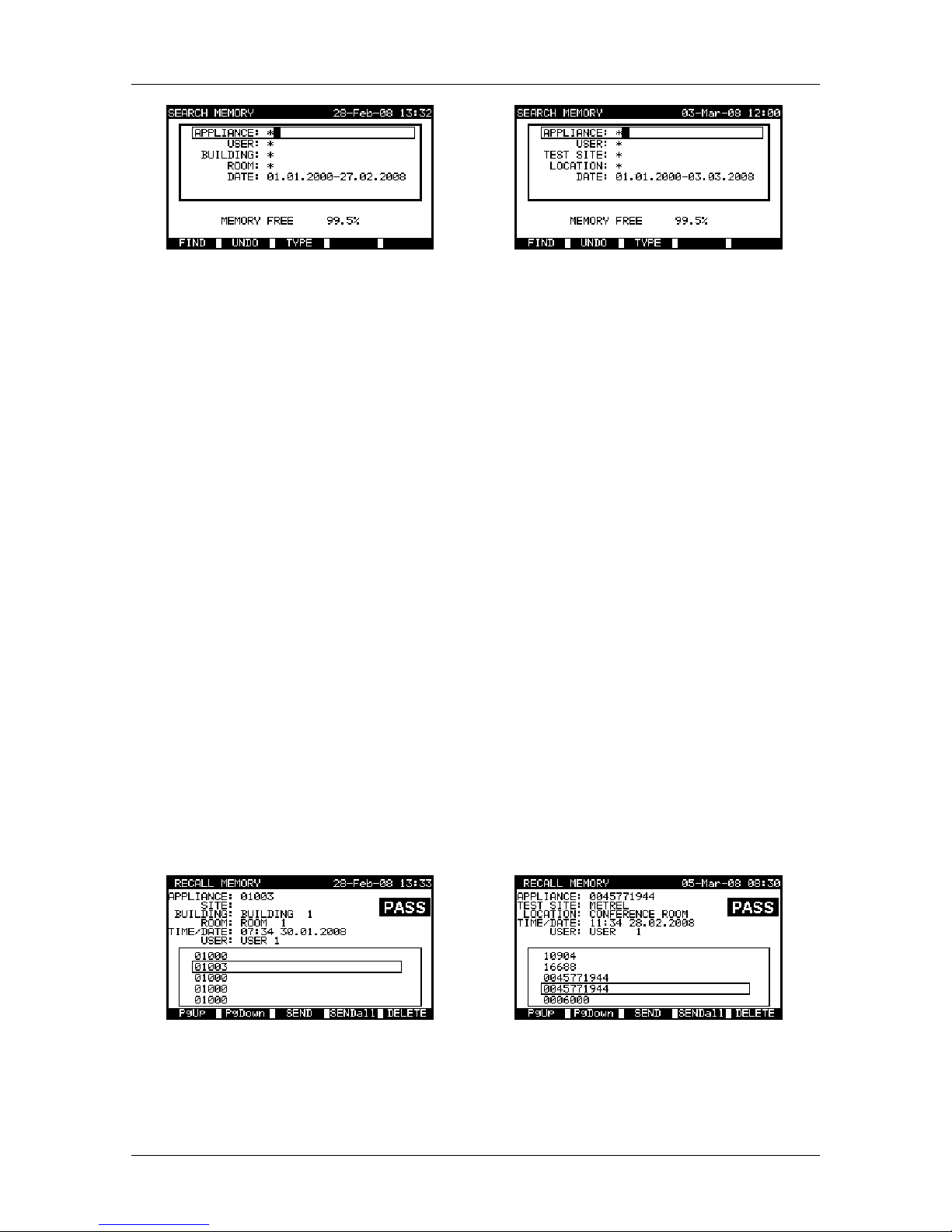
OmegaPATPlus / BetaPATPlus Working with autotest results
62
Aus / NZ model
UK model
Search results menu
When searching for stored results the following filters can be used to narrow the hits:
UK model Aus/ NZ model
Ì appliance number,
Ì test site,
Ì location,
Ì date from and date to,
Ì user.
Ì appliance number,
Ì building,
Ì room,
Ì date from and date to,
Ì user.
By using ¿ and À cursor keys select the filter you want to edit.
To change the selected parameter line type, press the F3 function key and the
»parameter type« will become highlited (e.g. Appliance). The ½ and ¾ cursor keys can
then be used to change the parameter type and by pressing ENTER key the choice can
be confirmed. Once the parameter types have been set up, the data required to filter the
files can be inserted. Filter information can be inserted via the alphanumeric keypad or,
in some filter fields such as user, can also be selected from a predefined list by pressing
the F4 function key. The Appliance number field can also be read using a barcode
reader.
By placing a »*« (shift + »2«) in a particular field, tells the instrument not to search the
associated filter field. When searching, the instrument will therefore ignore data in this
parameter and go on to find all the appliances that conform to data placed in the other
filter fields.
To find all stored results, enter »*« in the all fields (excluding Date where the correnct
froma and to dates must be entered).
When the search filters have been correctly set up, a search can be performed by
pressing the F1 function key. If the search filters are set up correctly and the appliances
exist in the units memory, the Recall results menu will be displayed.
Aus/ NZ model
UK model
Recall results menu
Page 63

OmegaPATPlus / BetaPATPlus Working with autotest results
63
While recalling stored results, instrument shows a bargraph and a ratio of files found
compared to files stored in memory (e.g. 17/89 implies 17 results have been found to
meet the filter citeria out of a potential 89 results stored in the flash memory).
Once the appliances have been found, the ¿ and À cursor keys and F1 and F2
function keys can be used to scrool through the list of appliances. More information
relating to an appliance can be viewed by pressing the ENTER key on the appropriate
appliance. The information can be scrolled using the F1 and F2 function keys and the
F5 function key can be used to switch between different appliance data views.
Aus/NZ model
UK model
View results menu
Use the ESC key to return to Recall results or Search results menus.
From the Recall results menu stored data can be downloaded to a PC, printed out to a
serial printer or deleted from the memory. Refer to chapters 8.4 Downloading and
printing results and 8.3 Deleting results, respectively.
Note on Aus/NZ model:
Ì Stored result with 2 appliances give 2 results. The number in brackets equals the
number of appliance IDs ((1) indicates results with one appliance ID and (2)
indicates results with two appliance IDs).For selected appliance number some
appliance data are also viewed in this menu.
8.3 Deleting results
Stored autotest results can also be deleted from the memory.
Enter Recall results menu from Main menu. Recall the result(s) you want to delete
(Refer to chapter
8.2 Recalling results for detailed information on recalling results).
In the Recall results menu, press F5 function key. Delete results menu will be
displayed.
Aus/ NZ model
UK model
Recall results menu
Page 64

OmegaPATPlus / BetaPATPlus Working with autotest results
64
Delete results menu
In this menu the following functions can be performed.
Ì DELETE: deletes the single file last highlited when the F5 function key was
pressed,
Ì DELETE SELECTED: deletes all the files found from searching the memory of
the instrument,
Ì DELETE ALL: clears all stored test data from the instrument.
By using ¿ and À cursor keys select the option required and press the F5 function key.
Confirm the delete activity by using Y key. After performing the selected option,
instrument returns to Recall results menu accepting the new memory state. If you don't
want delete the results, press the N key in Delete results menu. Instrument returns to
Recall results menu without any changes.
8.4 Downloading and printing results
Autotest results can be sent to the PC for other activities or printed out using a serial
printer or special label printers.
The autotest results can be downloaded to PC or sent to printer:
Ì after autotest sequence is completed, or
Ì after recalling stored results from the instrument memory.
By pressing the F3 function key in the Save results or Recall results menus, Send
results menu is available.
Send results menu
From this menu the autotest results can be:
Ì sent to PC, or
Ì printed out.
Page 65

OmegaPATPlus / BetaPATPlus Working with autotest results
65
By using ¿ and À cursor keys, select the activity you want to perform. The actual
settings for selected activity will be displayed under the activity box.
Use the F1 and F2 function keys to set the settings for selected activity, then press
ENTER key to start selected activity.
Refer to chapters 8.4.2 Settings for generic serial printer, 8.4.3 Settings for label
printers and 9.3.6 Instrument settings for more information.
..............................
METREL
Testing laboratory
Horjul, Slovenia
..............................
APPLIANCE 11072010
TEST SITE METREL
LOCATION OFFICE 1
TIME/DATE 09:31 11-JUL-2008
USER TOMAZ
RESULT: PASS
---------------------------------------VISUAL PASS
EARTH BOND It: 10A~ Rlim: 0.10 Ohm
1. R = 0.03 Ohm PASS
INSULATION Ut: 500V Rlim: 1.00 MOhm
1. R = 178.9 MOhm PASS
LEAKAGE Ut: 230V~ Ilim: 0.75 mA
1. I = 0.23 mA PASS
POWER
1. P = 2.01KVA PASS
APPLIANCE NAME: APP 1
RETEST PERIOD : 11/07/2009
REPAIRING CODE: 021268505
COMMENTS: ========================================
END OF DATA
..............................
METREL
Testing laboratory
Horjul, Slovenia
..............................
APPLIANCE 11072011
SITE METREL
BUILDING METREL
LOCATION OFFICE 1
TIME/DATE 09:54 11-JUL-2008
USER PETER
RESULT: PASS
---------------------------------------VISUAL PASS
EARTH BOND It: 10A~ Rlim: 1.00 Ohm
1. R = 0.21 Ohm PASS
INSULATION Ut: 500V Rlim: 1.00 MOhm
1. R = 161.3 MOhm PASS
APPLIANCE NAME: APP 1
RETEST PERIOD : 11/07/2009
REPAIRING CODE: 081276501
COMMENTS: ========================================
END OF DATA
UK model Aus/NZ model
Example of data sent to serial printer
1 tag, barcode system:
single (top label)
1 tag, barcode system:
double (bottom label)
2 tags, barcode system:
double
2 tags, barcode system:
single
Examples of appliance labels for UK model
Page 66

OmegaPATPlus / BetaPATPlus Working with autotest results
66
1 tag, barcode system: double 1 tag, barcode system: single
2 tags, barcode system: double 2 tags, barcode system: single
Examples of appliance labels for Aus/NZ model
Note:
Ì When working with serial printers, baud rate is set by default to 9600 bps.
Ì Printing appliance labels using label printers is password protected (Aus/NZ
model). For more information please contact your distributor.
8.4.1 Communication ports settings for communication with PC
Instrument includes both RS 232 and USB communication ports for communicating with
a PC.
The appropriate communication port can be set:
Ì when Send to PC option is selected in Send results menu,
Ì in Main menu / Setup / Set communication menu (refer to chapter 9.3.8
Communication settings for more information).
Press F1 function key in Send results menu to enter the Baud rate submenu.
Press F2 function key in Send results menu to enter the Communication port
submenu.
Page 67
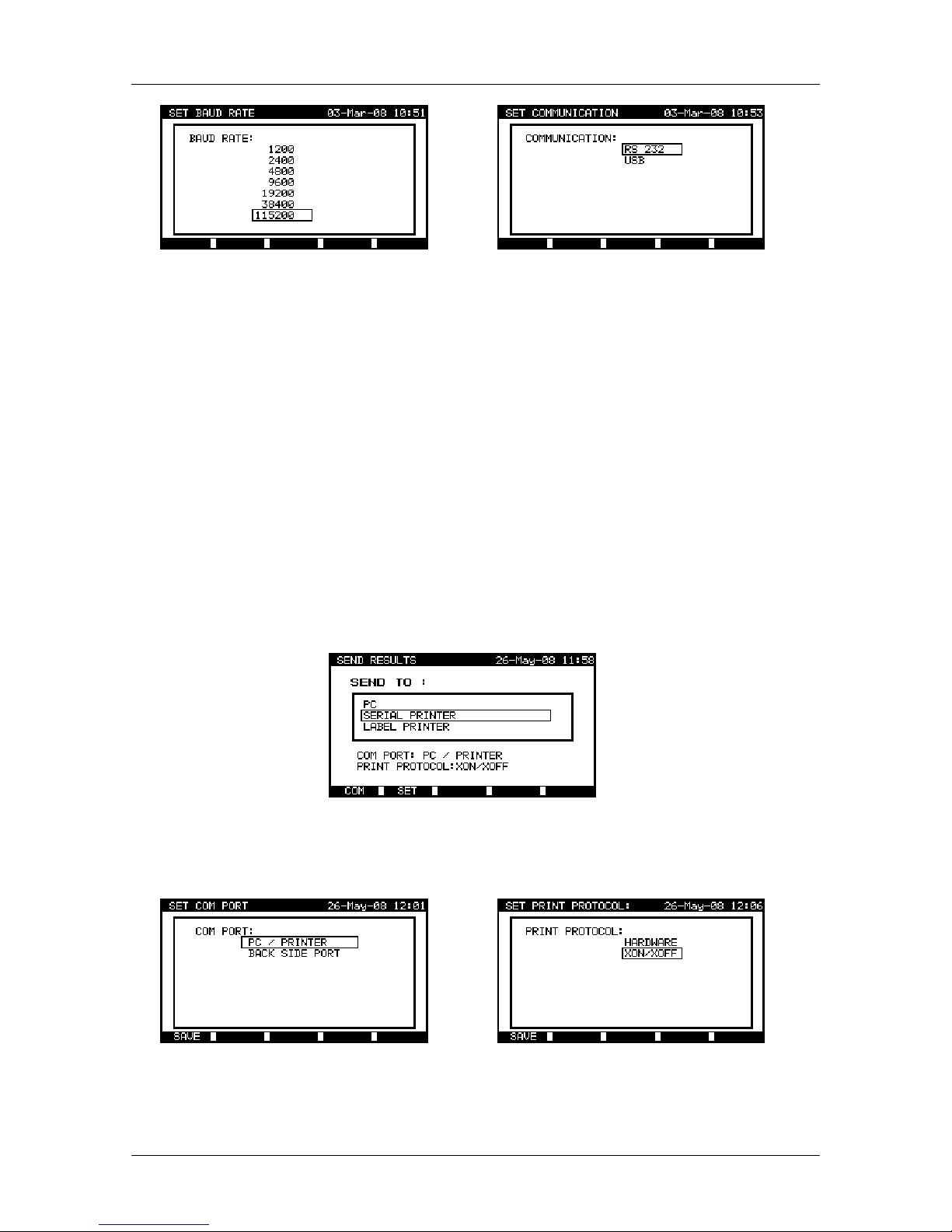
OmegaPATPlus / BetaPATPlus Working with autotest results
67
Communication ports settings
By using the ¿ and À cursor keys, select communication port / baud rate you want to
use for communication between instrument and PC. Once the communication port /
baud rate have been selected, press ENTER key to confirm. The instrument returns to
the Send results menu with new settings accepted.
By using the ESC key in Communication port or Baud rate submenu, the instrument
returns to the Send results menu without any changes.
Note:
Ì Only one port can be active at one time.
8.4.2 Settings for generic serial printer
Measuring results can be printed out on a serial printer via the RS232 (»PC/PRINTER«)
communication port. When a serial printer is used for printing autotest results,
communication port and printer data transfer protocol must first be selected correctly.
Sending results to serial printer
Press F1 function key in Send results menu to enter Communication port submenu.
Press F2 function key in Send results menu to enter Printer protocol submenu.
Communication port / printer protocol settings
Page 68

OmegaPATPlus / BetaPATPlus Working with autotest results
68
By using the ¿ and À cursor keys select communication port / printer protocol
supported by used serial printer.
Once the communication port / printer data transfer protocol is selected, press the F1
function key or ENTER key to confirm. The instrument will return to Send results menu
with new settings accepted.
By using the ESC key in the Communication port or Print protocol menu, the
instrument returns to Send results menu without any changes.
Notes:
Ì When working with serial printers, the baud rate is set by default to 9600 bps.
Ì Software transfer control uses XON (CTRL-Q) and XOFF (CTRL-S) characters.
Ì Hardware transfer control uses DTR line.
Ì Back side port supports only (XOn/XOff) software transfer control.
8.4.3 Settings for label printer
The instrument also supports printing appliance labels using special label printers:
Ì Printek Mobile MtP300 (supported for UK model)
Ì Printek MtP400 and Intermec EasyCoder C4 (supported for Aus / NZ model).
Aus / NZ model
UK model
Printing on special label printer
Aus / NZ model
Press the F1 function key in Send results menu to enter Printer submenu.
Sending results to serial printer
By using ¿ and À cursor keys select the label printer you want to use and press F1
function key or ENTER key to confirm. The instrument will return to Send results menu
with new settings accepted.
Page 69

OmegaPATPlus / BetaPATPlus Working with autotest results
69
By using ESC key in Label printer menu, the instrument will return to Send results
menu without any changes.
UK model
Press F4 function key in Send results menu to print one label.
Press F5 function key in Send results menu to print two the same labels.
Notes:
Ì Printing appliance labels using label printer is password protected (Aus / NZ
model). For more information please contact your distributor.
Ì Use serial port on the back side of the instrument when printing appliance labels
using Printek MtP400 / MtP300 printer.
Ì Use PC/PRINTER serial port when printing appliance labels using Intermec
EasyCoder C4 printer (Aus / NZ model).
Ì Do not connect Intermec EasyCoder C4 printer to the instrument when printing
test results using Serial printer option in the Send results menu. This may
damage label printer!
Page 70

OmegaPATPlus / BetaPATPlus Other instrument operations
70
9 Other instrument operations
9.1 User / appliance data menu
In the User / appliance data menu, user selection and list information can be edited. In
the Main menu, select User / appliance data ¿ and À cursor keys and pressing
ENTER key to confirm. The User / appliance data menu is displayed.
Aus/ NZ model
UK model
User / appliance data main menu
Existing user names and list data can also be downloaded and edited using PC
software and then uploaded back to the instrument. (Refer to the chapter 9.2 Data
upload / download for detailed information)
9.1.1 Users submenu
In this menu user names for up to 15 different users can be entered, edited and
selected.
Select Users in User / appliance data menu by ¿ and À cursor keys and press
ENTER key to confirm. The following menu is displayed:
Users submenu
How to rename an user name
To rename a selected user name press the F1 function key. Enter the new user name
and press F1 function key again to confirm or press ESC key to return to User menu
without saving.
By using F2 function key in Edit users submenu, user names can be reset to last
accepted name.
Page 71

OmegaPATPlus / BetaPATPlus Other instrument operations
71
9.1.2 Appliances submenu
In this menu, default lists of appliance names (up to 100) can be edited.
An alternative is to upload the names from PC software. For more information refer to
chapter 9.2 Data upload / download.
Select Appliances in User / appliance data menu by ¿ and À cursor keys and press
ENTER key to confirm. The following menu is displayed:
Appliances submenu
How to rename an appliance name
To rename a selected appliance name press F1 function key. Enter the new appliance
name and press F1 function key again to confirm or press the ESC key to return to the
Appliances menu without saving.
By using F2 function key in Set appliance submenu, appliance name can be reset to
last accepted name.
9.1.3 Test sites (UK model) / buildings (Aus/NZ model) submenu
In this menu default lists of test sites / building names (up to 100) can be edited.
An alternative is to upload the names from the PC software. The existing lists can also
be downloaded to a PC. For more information refer to chapter
9.2 Data upload /
download.
Select Test sites / Buildings in User / appliance data menu by ¿ and À cursor keys
and press ENTER key to confirm. The following menu will be displayed:
Aus/ NZ model
UK model
Test sites / buildings submenu
Page 72
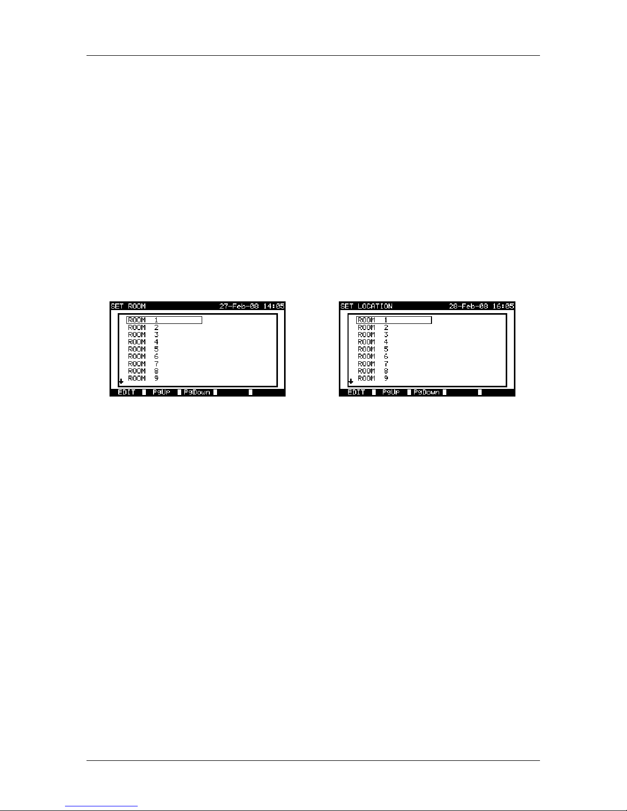
OmegaPATPlus / BetaPATPlus Other instrument operations
72
How to rename a test site / building name
To rename a selected test site / building name press F1 function key. Enter the new
name and press F1 function key again to confirm or press ESC key to return to Test
sites / Buildings menu without saving.
By using F2 function key in Edit test site / building submenu, test site / building name
can be reset to the last accepted name.
9.1.4 Locations (UK model) / rooms (Aus/NZ model) submenu
In this menu default lists of location / room names (up to 100) can be edited.
An alternative is to upload the names from the PC. The existing lists can also be
downloaded to PC. For more information refer to chapter 9.2 Data upload / download.
Select Locations / Rooms in User / appliance data main menu by ¿ and À cursor
keys and press ENTER key to confirm. The following menu is displayed:
Aus/ NZ model
UK model
Locations / rooms submenu
How to rename a location / room name
To rename a selected test site / building name press the F1 (EDIT) function key. Enter
the new name and press F1 (SAVE) function key again to confirm or press the ESC key
to return to Rooms / Locations menu without saving.
By using the F2 function key in Edit room / location submenu, room / location name
can be reset to the last accepted name.
9.2 Data upload / download
Autotests and results from PC software can be uploaded to the instrument from the
Data upload / download menu. Also the following items can be downloaded and
edited or created with PC software and then uploaded onto the instrument:
Ì users,
Ì appliances,
Ì test sites / buildings,
Ì locations / rooms.
Page 73

OmegaPATPlus / BetaPATPlus Other instrument operations
73
Downloading / uploading test data menu
During the data transfer from the PC to the instrument, the transfer status will be
displayed.
Pressing ESC key instrument returns to Main menu.
For detailed information on data uploading / downloading refer to help menus of PC
software PATLink PRO.
9.3 Setup menu
In Setup menu the general instrument parameters can be configured and saved.
To enter the Setup menu select Setup in Main menu using ¿ and À keys and press
ENTER key to confirm. Setup menu will be displayed.
Setup menu
9.3.1 Setting date and time
From the Main menu, select Setup and the select Date / time by using ¿ and À cursor
keys and press ENTER key to confirm. The following menu will be displayed:
Date and time menu
Page 74
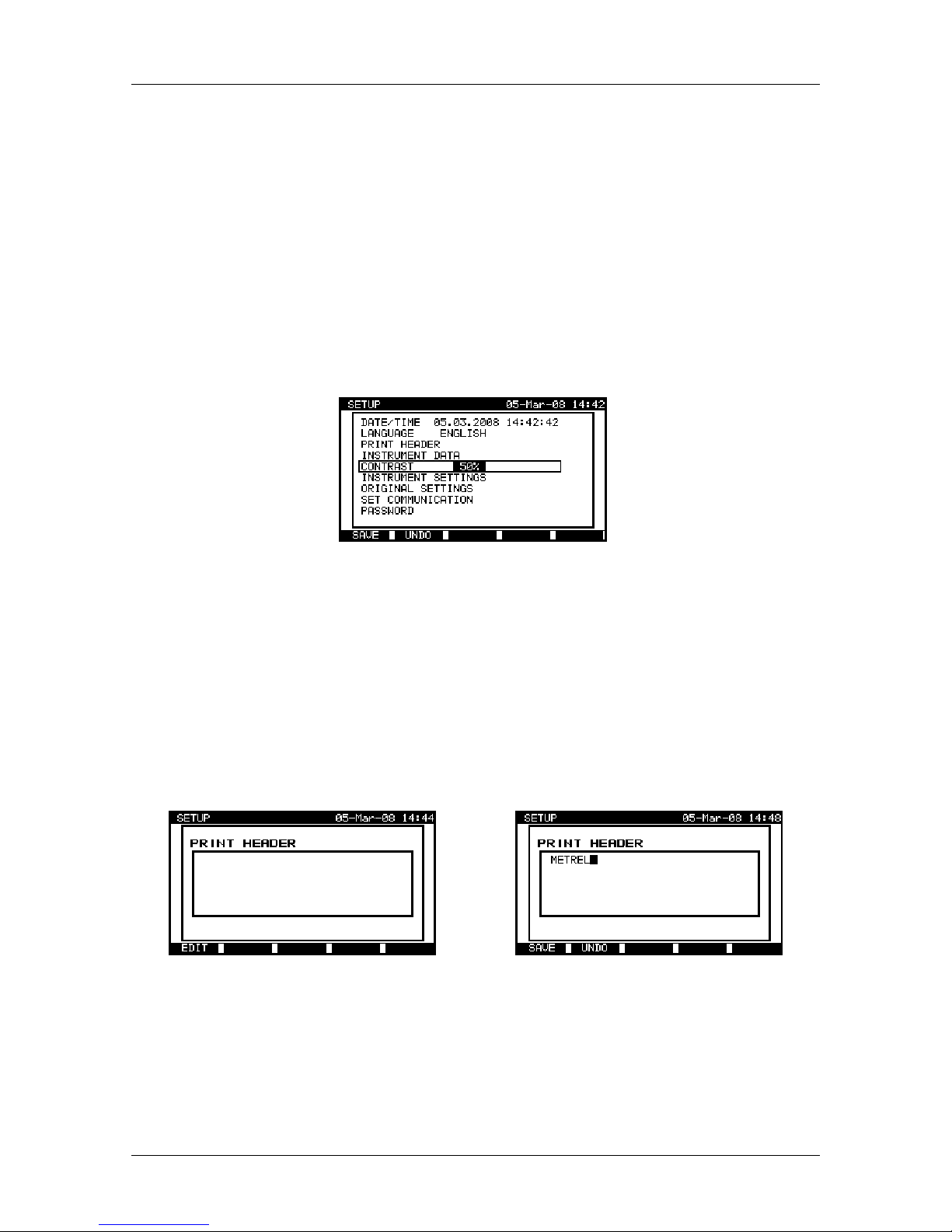
OmegaPATPlus / BetaPATPlus Other instrument operations
74
By using ½ and ¾ keys the date or time field can be selected. To set date and/or time
use ¿ and À cursor keys to change the date and time. Press the F1 function key to
accept the new settings or press ESC key to return to Setup menu without saving.
Notes:
Ì Date is attached to the saved autotest results!
Ì Date format is DD-MM-YYYY (day–month–year).
Ì Date entry is checked for regularity and not accepted in case of irregular date!
9.3.2 Display contrast adjustment
From the Main menu, select Setup and the select Contrast by using ¿ and À cursor
keys and press ENTER key to confirm. The following menu will be displayed:
Contrast menu
Use ¿ and À cursor keys to adjust contrast. Press F1 function key to accept the setting
or press ESC key to return to Setup menu without saving.
9.3.3 Print header
A print header can be set in the instrument which appears when printing autotest results
using a serial printer.
From the Main menu, select Setup and the select Print header by using ¿ and À
cursor keys and press ENTER key to confirm. The following menu will be displayed:
Print header menu
Editing print header
Press the F1 function key to enable print header editing and use the alpha-numeric
keyboard to edit print header field.
Press F1 function key again to confirm. Instrument returns to Setup menu.
By pressing ESC key instrument returns to Setup menu without accept new settings.
Page 75

OmegaPATPlus / BetaPATPlus Other instrument operations
75
9.3.4 Language selection
Select Language in Setup menu by using ¿ and À cursor keys and press ENTER key.
The following menu is displayed:
Language menu
By using ¿ and À cursor keys select language you want to use.
Press ENTER key to accept the new language or press ESC key to return to Setup
menu without any change.
9.3.5 Viewing of instrument data
In this menu the following instrument data are shown:
Ì producer name,
Ì instrument name,
Ì serial number,
Ì firmware version,
Ì calibration date.
Select Instrument data in Setup menu by using ¿ and À cursor keys and press
ENTER key. Instrument data menu is displayed.
Instrument data menu
Note:
Ì Operator cannot change any instrument data!
9.3.6 Instrument settings
When an autotest is completed, different data about appliance and other associated
data can be added to the autotest results before saving them. In the Instrument
settings submenu, the settings as to how the data changes between tests can be
controlled.
Page 76

OmegaPATPlus / BetaPATPlus Other instrument operations
76
From the Main menu, select Setup and then select Instrument settings by using ¿
and À cursor keys and press ENTER key to confirm. The Instrument settings
submenu will be displayed.
Aus/ NZ model
UK model
Instrument settings menu
The following data can be controlled between tests:
UK model Aus/ NZ model
Ì appliance number,
Ì test site,
Ì location,
Ì user,
Ì appliance name,
Ì retest period
Ì repairing code,
Ì comments,
Ì barcode system.
Ì appliance number,
Ì site,
Ì building,
Ì room,
Ì user,
Ì appliance name,
Ì retest period,
Ì repairing code,
Ì comments,
Ì barcode system,
Ì second tag manipulation.
By using ¿ and À cursor keys select the item whose parameter you want to change
and press ENTER key to confirm. Use ¿ and À cursor keys again to set parameter to
your needs. Press F1 function key to confirm. To restore last used setting for selected
item press F2 key.
In general, the blank and replicate options are available. If blank is selected for a
particular item, then the appropriate field will initially appear blank in the Save results
menu. If replicate option is selected for a particular item, the last entered data will
initially appear in an appropriate field when new autotest sequence is finished.
The increment option can also be set in the appliance number field. In this case, the
appliance number will be automatically incremented when new autotest sequence is
finished.
Notes on Aus/NZ model:
Ì The 2nd appliance number and its name can also be added to the actual autotest
results. To activate this functionality enable the 2
nd
tag manipulation. When 2nd
tag manipulation is disabled, then only one appliance number and its name is
available in Save results menu when new autotest sequence is finished.
Ì When 2
nd
tag manipulation is enabled, two appliance barcode labels are
printed out.
Page 77

OmegaPATPlus / BetaPATPlus Other instrument operations
77
Special label printer (Printek MtP300 / MtP400, Intermec EasyCoder C4) is also
supported by the instrument. When printing barcodes to the special printer, two different
options can be set in Barcode systems submenu. If single option is selected, only
appliance name is printed out as a barcode on appliance barcode label. When double
is selected, both autotest shortcut code and appliance name are printed out as a
barcode on appliance barcode label.
Notes on Aus/NZ model:
Ì Special characters (?, > or <) between autotest shortcut code and appliance
name (ID number) are used to identify single or double tag. Symbol '?' means
that only one tag was used for appliance. Symbols '<' and '>' indicate that two
appliance IDs were stored after performing autotest sequence and also two tags
were printed out.
Ì Only appliance ID is printed out on the 2
nd
appliance label (power supply cord
label).
Notes on UK model:
Ì Special character »$« between autotest shortcut code and appliance name (ID
number) is used to distinguish shortcut code from appliance name.
Ì Only appliance ID is printed out on the 2
nd
appliance label (power supply cord
label).
9.3.7 Password
In password protected actions, it is necessary to enter the password before deleting or
editing the protected data. The instrument requires a password and it will not allow
changes unless the correct password has been entered.
From the Main menu, select Setup and the select Password by using ¿ and À cursor
keys and press ENTER key to confirm. Password submenu will be displayed.
Password menu
Enter a password and then press ENTER key to accept the new password. By pressing
the ESC key instrument returns to Setup menu without any changes.
Please take a note of this password and keep it in a safe place.
If there is no password protection, the instrument will request that you enter a new
password twice, once to confirm.
Page 78

OmegaPATPlus / BetaPATPlus Other instrument operations
78
If the instrument is already password protected, then the instrument will request the old
password before entering the new one twice, once to confirm.
To disable the password protection, instead of entering a new password just press the
ENTER key when asked for a new password and confirmation and the password will be
disabled.
If you forget the password, contact your dealer.
Password protected actions:
Ì entering Edit user menu,
Ì editing measurement parameters in single / autotest custom test mode,
Ì deleting stored results,
Ì entering Original settings menu.
9.3.8 Communication settings
In this menu, the communication port and baud rate can be set for communication with
PC.
From the Main menu, select Setup and then select Communication by using ¿ and À
cursor keys and pressing ENTER key. The following menu will be displayed:
Communication menu
By using ¿ and À cursor keys select option you want to change and press ENTER key
to confirm. One of the following menus is displayed:
Communication settings
By using ¿ and À cursor keys, select the communication port / baud rate you want to
use for communication between instrument and PC. Once the communication port /
baud rate is selected, press the ENTER key (or F1 function key) to confirm. The
instrument returns to Communication menu with new settings accepted.
Page 79

OmegaPATPlus / BetaPATPlus Other instrument operations
79
By using ESC key in the Communication port or Baud rate submenu, the instrument
will return to Communication menu without any changes.
Note:
Ì Only one port can be active at one time.
9.3.9 Reset instrument settings
In this menu the following parameters can be set to their initial values:
Ì all measurement parameters in single test mode,
Ì user defined tests are cleared,
Ì 8 autotest sequences with all measurements disabled are added,
Ì all menus are set to their initial structure,
Ì PC baud rate is set to 115000 bps,
Ì printer protocol is set to hardware (DTR).
Select Original settings in Setup menu by using ¿ and À cursor keys and press
ENTER key to confirm. The following menu is displayed:
Original settings menu
Select YES to confirm, or NO to quit without changes.
Page 80

OmegaPATPlus / BetaPATPlus Maintenance
80
10 Maintenance
10.1 Periodic calibration
It is essential that all measuring instruments are regularly calibrated in order for the
technical specification listed in this manual to be guaranteed. We recommend an annual
calibration. The calibration should be done by an authorized technical person only.
10.2 Fuses
There are two fuses available from front panel:
F1 = F2 = T 16 A / 250 V (32 × 6,3 mm): intended for instrument protection.
If the instrument does not respond after connection to mains supply, disconnect the
mains supply and accessories and then check these fuses. For position of fuses refer to
chapter 2.1 Front panel.
Warning!
Ì Switch off the instrument and disconnect all test accessories and mains cord
before replacing the fuses or opening the instrument. Disconnect all test leads
and the instrument mains cord before removing fuse cover!
Ì Replace blown fuse with the same type.
10.3 Service
For repairs under or out of warranty time please contact your distributor for further
information.
Unauthorized person is not allowed to open the OmegaPATPlus / BetaPATPlus
instrument. There are no user replaceable components inside the instrument.
10.4 Cleaning
Use a soft, slightly moistened cloth with soap water or alcohol to clean the surface of
OmegaPATPlus / BetaPATPlus instrument. Leave the instrument to dry totally before
using it.
Notes:
Ì Do not use liquids based on petrol or hydrocarbons!
Ì Do not spill cleaning liquid over the instrument!
Page 81

OmegaPATPlus / BetaPATPlus Instrument set and accessories
81
11 Instrument set and accessories
Standard set of the instrument
Ì Instrument MI 3305 – OmegaPATPlus / MI 3304 – BetaPATPlus
Ì Additional bag for accessories inside carrying case
Ì Test probe (earth bond clip)
Ì Flash test probe (MI 3305 only)
Ì PRCD test probe
Ì Test lead (1.5 m, green)
Ì Test lead (1.5 m, black)
Ì Test tip (green)
Ì Test tip (black)
Ì Aligator clip (green)
Ì Aligator clip (black)
Ì PC software PATLink PRO with RS232 and USB cables
Ì User manual
Ì Production verification data
Optional accessories
See the attached sheet for a list of optional accessories that are available on request
from your distributor.
Page 82

OmegaPATPlus / BetaPATPlus Autotest shortcut parameters
82
A Autotest shortcut parameters
APPLIANCE TYPE
Ì portable or handheld appliances,
Ì heating and cooking appliances,
Ì IT (information technology) equipment (EN60950),
Ì extension leads,
Ì 3-phase (Aus / NZ model only),
Ì multibox (Aus / NZ model only),
Ì mineral insulated heating elements (Aus / NZ model only),
Ì RCD protected appliances (Aus / NZ model only).
Most electrical appliances belong to one of these above-mentioned types. The tests and
limits differ slightly depending on the specific regulation.
In general the following tests must be performed during an in service test:
Class I equipment:
Ì visual check,
Ì earth bond resistance,
Ì insulation resistance,
Ì functional test.
Class II equipment:
Ì visual check,
Ì insulation resistance,
Ì functional test.
Notes:
Ì For portable and handheld appliances the leakage (or touch leakage) limits are
stricter than for other types.
Ì For IT equipment the earth bond resistance measurement is performed with low
current (100 mA) in order to avoid any damage to earth connections for EMC
(screening) purposes.
Ì For cooking and heating appliances the leakage limit is set higher because some
leakage typically occurs in the heating elements. Therefore the substitute
leakage current measurement is performed instead of insulation resistance
measurement.
Ì The IT equipment must conform to the EN60950 regulations. Otherwise the
equipment may be damaged during the insulation resistance measurement!
APPLIANCE SAFETY CLASS
Ì Class I
Ì Class II
Page 83

OmegaPATPlus / BetaPATPlus Autotest shortcut parameters
83
FUSE: 3 A (750 VA), 6 A (1.5 kVA), 10 A (2.5 kVA), 13 A (3.2 kVA), unknown
SUPPLY CORD: short, middle (or low c.s.a.), long
Cord
Earth bond
limit
Appliance
fuse
Power
Nominal
conuctor
c.s.a.
Appliance
supply cord
length
3 A 750 VA
0.5 mm2
(39 mΩ/m)
2.5 m
6 A 1.5 kVA 0.75 mm2 3.5 m
10 A 2.5 kVA 1 mm2 5 m
SHORT
0.10 Ω
13 A 3.2 kVA 1.25 mm2 6 m
3 A 750 VA 0.5 mm2 7.5 m
6 A 1.5 kVA 0.75 mm2 11.5 m
10 A 2.5 kVA 1 mm2 15 m
MIDDLE
0.30 Ω
13 A 3.2 kVA 1.25 mm2 19 m
3 A 750 VA 0.5 mm2 12.5 m
6 A 1.5 kVA 0.75 mm2 19 m
10 A 2.5 kVA 1 mm2 25 m
LONG
0.50 Ω
13 A 3.2 kVA 1.25 mm2 32 m
Nominal conductor c.s.a. Nominal conductor
resistance
0.5 mm2
39 mΩ/m
0.75 mm2
26 mΩ/m
1 mm2
19.5 mΩ/m
1.25 mm2
15.6 mΩ/m
See Code of practice for in-service inspection and testing of electrical equipment, 3rd
edition, page 124
Ì The earth bond limit depends signlificantly on the supply cord length and its PE
wire cross-section area.
Ì SHORT should be set for appliances with a cord not longer than 5 m.
Ì MEDIUM can be used when the appliance supply cord is longer than 5 m or the
cord wire has a small cross-section area.
Ì LONG can be used if the appliance has a very long supply cord (for instance
vaccum cleaners).
Ì The power means the maximum power that can be delivered in combination with
the set fuse. Some users are more familiar with the nominal power than the fuse
rating.
FUNCTIONAL / PROTECTIVE CONDUCTOR TEST: yes, no
LENGTH: ≤ 5 m, 7.5 m, 10 m, 12 m, 15 m, 20 m, 30 m, 40 m, 50 m
CONDUCTOR CROSS-SECTION: 0.5 mm
2
, 0.75 mm2, 1.0 mm2, 1.25 mm2, 1.5 mm2,
unknown
MAX. CURRENT CAPACITY: 3 A (<750 VA), 6A (1.5 kVA), 10 A (2.5 kVA), 13 A (3.2
kVA), 15 A (3.75 kVA)
Page 84

OmegaPATPlus / BetaPATPlus Autotest shortcut codes
84
B Autotest shortcut codes (Aus / NZ model)
Code
No.
Visual
001
;
Portable or handheld
Code
No.
Class Visual Earth bond (1st test) Eart bond (2nd test) Insulation Substitute
leakage
Leakage Touch
leakage
Polarity
test
TRMS current
(current clamp adapter)
Test
current
Pass
limit
Test
duration
Test
current
Pass
limit
Test
duration
Test
voltage
Pass
limit
Test
duration
Pass
limit
Test
duration
Pass
limit
Time
duration
101 1
;
10 A
1.00 Ω
5 s
:
500 V
1.00 MΩ
3 s
: : : : :
102 1
;
25 A
1.00 Ω
5 s
:
500 V
1.00 MΩ
3 s
: : : : :
103 1
;
10 A
1.00 Ω
5 s
: : :
5.00 mA 5 s
: : :
104 1
;
25 A
1.00 Ω
5 s
: : :
5.00 mA 5 s
: : :
105 1
;
10 A
1.00 Ω
5 s
:
250 V
1.00 MΩ
3 s
: : : : :
106 1
;
25 A
1.00 Ω
5 s
:
250 V
1.00 MΩ
3 s
: : : : :
107 1
;
10 A
0.50 Ω
5 s
:
500 V
2.00 MΩ
3 s
: : : : :
108 1
;
25 A
0.50 Ω
5 s
:
500 V
2.00 MΩ
3 s
: : : : :
109 1
;
10 A
0.50 Ω
5 s
: : :
3.50 mA 5 s
: : :
110 1
;
25 A
0.50 Ω
5 s
: : :
3.50 mA 5 s
: : :
111 1
;
10 A
0.50 Ω
5 s
:
250 V
2.00 MΩ
3 s
: : : : :
112 1
;
25 A
0.50 Ω
5 s
:
250 V
2.00 MΩ
3 s
: : : : :
170 1
;
25 A
1.00 Ω
5 s
: : :
5.00 mA 30 s
: : :
171 1
;
25 A
1.00 Ω
3 s
:
500 V
1.00 MΩ
3 s
:
5.00 mA 5 s
: :
5.00 mA 5 s
172 1
;
25 A
1.00 Ω
3 s
:
500 V
1.00 MΩ
3 s
:
1.00 mA 5 s
: :
1.00 mA 5 s
173 1
;
25 A
1.00 Ω
3 s
: : :
1.00 mA 5 s
: : :
174 1 ; 100 mA
1.00 Ω
3 s 25 A
1.00 Ω
3 s
: :
5.00 mA 5 s
: : :
175 1 ; 100 mA
1.00 Ω
3 s 25 A
1.00 Ω
3 s 500 V
1.00 MΩ
3 s
: : : : :
201 2
; : :
500 V
1.00 MΩ
5 s
: : : : :
202 2
; : :
500 V
2.00 MΩ
5 s
: : : : :
203 2
; : :
250 V
1.00 MΩ
5 s
: : : : :
204 2
; : :
500 V
2.00 MΩ
5 s
: : : : :
205 2
; : :
500 V
1.00 MΩ
5 s
: : : : :
206 2
; : :
500 V
2.00 MΩ
5 s
: : : : :
207 2
; : :
500 V
0.01 MΩ
5 s
: : : : :
208 2
; : : : :
1.00 mA 5 s
: : :
209 2
; : : : :
0.50 mA 5 s
: : :
218 2
; : : : :
1.00 mA 30 s
: : :
219 2
; : :
250 V
10.00 MΩ
3 s
: : : : :
220 2
; : :
500 V
10.00 MΩ
3 s
: : : : :
Page 85

OmegaPATPlus / BetaPATPlus Autotest shortcut codes
85
IT equipment (EN 60950)
Code
No.
Class Visual Earth bond (1st test) Eart bond (2nd test) Insulation Substitute
leakage
Leakage Touch
leakage
Polarity
test
TRMS current
(current clamp adapter)
Test
current
Pass
limit
Test
duration
Test
voltage
Pass
limit
Test
duration
Pass
limit
Test
duration
121 1 ; 100 mA
1.00 Ω
5 s
:
500 V
1.00 MΩ
3 s
: : : : :
122 1 ; 100 mA
1.00 Ω
5 s
:
250 V
1.00 MΩ
3 s
: : : : :
123 1 ; 100 mA
0.50 Ω
5 s
:
500 V
2.00 MΩ
3 s
: : : : :
124 1 ; 100 mA
0.50 Ω
5 s
:
250 V
2.00 MΩ
3 s
: : : : :
125 1 ; 100 mA
1.00Ω
5 s
: : :
5.00 mA 3 s
: : :
126 1 ; 100 mA
0.50 Ω
5 s
: : :
3.50 mA 3 s
: : :
210 2
; : :
500 V
1.00 MΩ
3 s
: : : : :
211 2
; : :
250 V
1.00 MΩ
3 s
: : : : :
212 2
; : :
500 V
2.00 MΩ
3 s
: : : : :
213 2
; : :
250 V
2.00 MΩ
3 s
: : : : :
214 2
; : : : :
1.00 mA 5 s
: : :
215 2
; : : : :
0.50 mA 5 s
: : :
IEC leads / Extension leads
Code
No.
Class Visual Earth bond (1st test)
Earth bond (2nd test) Insulation Substitute
leakage
Leakage Touch
leakage
Polarity
test
TRMS current
(current clamp adapter)
Test
current
Pass
limit
Test
duration
Test
current
Pass
limit
Test
duratio
n
Test
voltage
Pass
limit
Test
duration
Pass
limit
Test
duration
127 1 ; 100 mA
1.00 Ω
5 s 25 A
1.00 Ω
2 s 500 V
1.00 MΩ
3 s
: : : ; :
128 1 ; 100 mA
1.00 Ω
5 s
:
500 V
1.00 MΩ
3 s
: : : : :
129 1
;
10 A
1.00 Ω
5 s
:
500 V
1.00 MΩ
3 s
: : : ; :
130 1
;
10 A
1.00 Ω
5 s
:
500 V
1.00 MΩ
3 s
: : : : :
131 1
;
25 A
1.00 Ω
5 s
:
500 V
1.00 MΩ
3 s
: : : ; :
132 1
;
25 A
1.00 Ω
5 s
:
500 V
1.00 MΩ
3 s
: : : : :
133 1 ; 100 mA
0.50 Ω
5 s
:
500 V
1.00 MΩ
3 s
: : : : :
134 1 ; 100 mA
0.50 Ω
5 s 25 A
0.50 Ω
2 s 500 V
1.00 MΩ
3 s
: : : ; :
135 1 ; 100 mA
0.50 Ω
5 s
:
500 V
1.00 MΩ
3 s
: : : : :
136 1 ; 100 mA
1.00 Ω
5 s
:
500 V
1.00 MΩ
3 s
: : : : :
137 1
;
10 A
0.50 Ω
5 s
:
500 V
2.00 MΩ
3 s
: : : ; :
138 1
;
25 A
0.50 Ω
5 s
:
500 V
2.00 MΩ
3 s
: : : ; :
139 1 ; 100 mA
1.00 Ω
5 s
: : :
1.00 mA 5 s
: ; :
140 1 ; 100 mA
1.00 Ω
5 s
: : :
1.00 mA 5 s
: : :
141 1
;
10 A
1.00 Ω
5 s
: : :
1.00 mA 5 s
: ; :
142 1
;
10 A
1.00 Ω
5 s
: : :
1.00 mA 5 s
: : :
143 1
;
25 A
1.00 Ω
5 s
: : :
1.00 mA 5 s
: ; :
144 1
;
25 A
1.00 Ω
5 s
: : :
1.00 mA 5 s
: ; :
217 2
; : :
500 V
1.00 MΩ
3 s
: : : ; :
Heating and Cooking
Code
No.
Class Visual Earth bond (1st test) Eart bond (2nd test) Insulation Substitute
leakage
Leakage Touch
leakage
Polarity
test
TRMS current
(current clamp adapter)
Test
current
Pass
limit
Test
duration
Test
voltage
Pass
limit
Test
duration
113 1
;
10 A
1.00 Ω
5 s
:
500 V
1.00 MΩ
3 s
: : : : :
114 1
;
25 A
1.00 Ω
5 s
:
500 V
1.00 MΩ
3 s
: : : : :
115 1
;
10 A
0.50 Ω
5 s
:
500 V
2.00 MΩ
3 s
: : : : :
116 1
;
25 A
0.50 Ω
5 s
:
500 V
2.00 MΩ
3 s
: : : : :
117 1
;
10 A
1.00 Ω
5 s
:
500 V
0.01 MΩ
3 s
: : : : :
118 1
;
25 A
1.00 Ω
5 s
:
500 V
0.01 MΩ
3 s
: : : : :
119 1
;
10 A
0.50 Ω
5 s
:
500 V
0.01 MΩ
3 s
: : : : :
120 1
;
25 A
0.50 Ω
5 s
:
500 V
0.01 MΩ
3 s
: : : : :
Page 86

OmegaPATPlus / BetaPATPlus Autotest shortcut codes
86
IEC leads / Extension leads
Code
No.
Class Visual Earth bond (1st test)
Continuous mode
Earth bond (2nd test) Insulation Substitute
leakage
Leakage Touch
leakage
Polarity
test
TRMS current
(current clamp adapter)
Test
current
Pass
limit
Test
duration
Pass
limit
Test
duration
145 1 ; 100 mA
1.00 Ω
5 s
: : :
1.00 mA 5 s
: ; :
146 1 ; 100 mA
1.00 Ω
5 s
: : :
1.00 mA 5 s
: : :
147 1
;
25 A
1.00 Ω
5 s
: : :
1.00 mA 5 s
: ; :
148 1
;
25 A
1.00 Ω
5 s
: : :
1.00 mA 5 s
: : :
3-phase
Code
No.
Class Visual Earth bond (1st test)
Continuous mode
Earth bond (2nd test) Insulation Substitute
leakage
Leakage Touch
leakage
Polarity
test
TRMS current
(current clamp adapter)
Test
current
Pass
limit
Test
duration
Pass
limit
Test
duration
149 1
;
10 A
1.00 Ω
5 s
: : : : : :
1.00 mA 5 s
150 1
;
10 A
1.00 Ω
5 s
: : : : : :
5.00 mA 5 s
151 1
;
25 A
1.00 Ω
5 s
: : : : : :
1.00 mA 5 s
152 1
;
25 A
1.00 Ω
5 s
: : : : : :
5.00 mA 5 s
153 1
;
10 A
1.00 Ω
5 s
: : : : : :
1.00 mA 30 s
154 1
;
10 A
1.00 Ω
5 s
: : : : : :
5.00 mA 30 s
155 1
;
25 A
1.00 Ω
5 s
: : : : : :
1.00 mA 30 s
156 1
;
25 A
1.00 Ω
5 s
: : : : : :
5.00 mA 30 s
157 1
;
25 A
1.00 Ω
5 s
: : : : : :
5.00 mA 120 s
158 1
;
25 A
1.00 Ω
5 s
: : : : : :
5.00 mA 180 s
216 2
; : : : : : : :
1.00 mA 5 s
Mineral insulated elements
Code
No.
Class Visual Earth bond (1st test)
Continuous mode
Earth bond (2nd test) Insulation Substitute
leakage
Leakage Touch
leakage
Polarity
test
TRMS current
(current clamp adapter)
Test
current
Pass
limit
Test
duration
Test
voltage
Pass
limit
Test
duration
Pass
limit
Test
duration
159 1
;
10 A
1.00 Ω
5 s
:
500 V
0.10 MΩ
3 s
: : : : :
160 1
;
10 A
1.00 Ω
5 s
:
500 V
0.01 MΩ
3 s
: : : : :
161 1
;
25 A
1.00 Ω
5 s
:
500 V
0.01 MΩ
3 s
: : : : :
162 1
;
10 A
1.00 Ω
5 s
: : :
2.50 mA 5 s
: : :
Multibox
Code
No.
Class Visual Earth bond (1st test)
Continuous mode
Earth bond (2nd test)
Continuous mode
Insulation Substitute
leakage
Leakage Touch
leakage
Polarity
test
TRMS current
(current clamp adapter)
Test
current
Pass
limit
Test
duration
Test
current
Pass
limit
Test
duration
Test
voltage
Pass
limit
Test
duration
Pass
limit
Test
duration
163 1
;
100 mA
0.50 Ω
3 s 25 A
0.50 Ω
2 s 500 V
1.00 MΩ
3 s
: : : ; :
164 1
;
100 mA
1.00 Ω
3 s
:
500 V
1.00 MΩ
3 s
: : : ; :
165 1
;
100 mA
0.50 Ω
3 s 25 A
0.50 Ω
2 s 250 V
1.00 MΩ
3 s
: : : ; :
166 1
;
100 mA
1.00 Ω
3 s
:
250 V
1.00 MΩ
3 s
: : : ; :
167 1
;
100 mA
0.50 Ω
3 s
: : :
1.00 mA 5 s
: : :
168 1
;
100 mA
1.00 Ω
3 s 25 A
1.00 Ω
2 s
: :
1.00 mA 5 s
: : :
169 1
;
100 mA
1.00 Ω
3 s
: : :
5.00 mA 5 s
: : :
Page 87

OmegaPATPlus / BetaPATPlus Autotest shortcut codes
87
RCD protected appliances
Code
No.
Class Visual Earth bond (1st test)
Continuous mode
Earth bond (2nd test)
Continuous mode
Insulation Substitute
leakage
Leakage Touch
leakage
Polarity
test
TRMS current (current
clamp adapter)
Portable RCD test
Test
current
Pass
limit
Test
duration
Test
current
Pass
limit
Test
duration
Pass
limit
Test
duration
IΔN
Test:
180 1
;
100 mA
1.00 Ω
3 s 25 A
1.00 Ω
2 s
: :
2.50 mA 5 s
: ; :
10 mA Auto
181 1
;
100 mA
1.00 Ω
3 s 25 A
1.00 Ω
2 s
: :
2.50 mA 5 s
: : :
10 mA Auto
182 1
;
100 mA
1.00 Ω
3 s 25 A
1.00 Ω
2 s
: :
2.50 mA 5 s
: ; :
15 mA Auto
183 1
;
100 mA
1.00 Ω
3 s 25 A
1.00 Ω
2 s
: :
2.50 mA 5 s
: : :
15 mA Auto
184 1
;
100 mA
1.00 Ω
3 s 25 A
1.00 Ω
2 s
: :
2.50 mA 5 s
: ; :
30 mA Auto
185 1
;
100 mA
1.00 Ω
3 s 25 A
1.00 Ω
2 s
: :
2.50 mA 5 s
: : :
30 mA Auto
Meaning of symbols used in autotest shortcut codes tables: ; test/measurement enabled, : test/measurement disabled
Page 88

OmegaPATPlus / BetaPATPlus Autotest shortcut codes
88
C Autotest shortcut codes (UK model)
Type
Class Fuse Cord Earth Bond
Limit Out
Insulation
Limit Out
S. Leakage
Limit
Leakage
Limit
T. Leakage
Limit
Code
Portable or
Handheld
I 3 A short 0.10 Ω 10 A 1.00 MΩ 500 V - 0.75 mA - 001
I 6 A short 0.10 Ω 10 A 1.00 MΩ 500 V - 0.75 mA - 002
I 10 A short 0.10 Ω 25 A 1.00 MΩ 500 V - 0.75 mA - 003
I 13 A short 0.10 Ω 25 A 1.00 MΩ 500 V - 0.75 mA - 004
I 3 A short 0.10 Ω 10 A 1.00 MΩ 500 V - - - 005
I 6 A short 0.10 Ω 10 A 1.00 MΩ 500 V - - - 006
I 10 A short 0.10 Ω 25 A 1.00 MΩ 500 V - - - 007
I 13 A short 0.10 Ω 25 A 1.00 MΩ 500 V - - - 008
I 3 A midd 0.30 Ω 10 A 1.00 MΩ 500 V - 0.75 mA - 009
I 6 A midd 0.30 Ω 10 A 1.00 MΩ 500 V - 0.75 mA - 010
I 10 A midd 0.30 Ω 25 A 1.00 MΩ 500 V - 0.75 mA - 011
I 13 A midd 0.30 Ω 25 A 1.00 MΩ 500 V - 0.75 mA - 012
I 3 A midd 0.30 Ω 10 A 1.00 MΩ 500 V - - - 013
I 6 A midd 0.30 Ω 10 A 1.00 MΩ 500 V - - - 014
I 10 A midd 0.30 Ω 25 A 1.00 MΩ 500 V - - - 015
I 13 A midd 0.30 Ω 25 A 1.00 MΩ 500 V - - - 016
I 3 A long 0.50 Ω 10 A 1.00 MΩ 500 V - 0.75 mA - 017
I 6 A long 0.50 Ω 10 A 1.00 MΩ 500 V - 0.75 mA - 018
I 10 A long 0.50 Ω 25 A 1.00 MΩ 500 V - 0.75 mA - 019
I 13A long 0.50 Ω 25 A 1.00 MΩ 500 V - 0.75 mA - 020
I 3 A long 0.50 Ω 10 A 1.00 MΩ 500 V - - - 021
I 6 A long 0.50 Ω 10 A 1.00 MΩ 500 V - - - 022
I 10 A long 0.50 Ω 25 A 1.00 MΩ 500 V - - - 023
I 13 A long 0.50 Ω 25 A 1.00 MΩ 500 V - - - 024
II - - - - 2.00 MΩ 500 V - 0.25 mA - 025
II - - - - 2.00 MΩ 500 V - - - 026
Type
Class Fuse Cord Earth Bond
Limit Out
Insulation
Limit Out
S. Leakage
Limit
Leakage
Limit
T. Leakage
Limit
Code
Heating and
Cooking
I 3 A short 0.10Ω 10 A - - - 0.75 mA - 027
I 6 A short 0.10 Ω 10 A - - - 1.00 mA - 028
I 10 A short 0.10 Ω 25 A - - - 1.50 mA - 029
I 13 A short 0.10 Ω 25 A - - - 2.25 mA - 030
I 3 short 0.10 Ω 10 A - - 0.75 mA - - 031
I 6 A short 0.10 Ω 10 A - - 1.00 mA - - 032
I 10 A short 0.10 Ω 25 A - - 1.50 mA - - 033
I 13 A short 0.10 Ω 25 A - - 2.25 mA - - 034
II - - - - 2.00 MΩ 500 V - 0.25 mA - 035
II - - - - 2.00 MΩ 500 V - - - 036
Page 89

OmegaPATPlus / BetaPATPlus Autotest shortcut codes
89
Type
Class Fuse Cord Earth Bond
Limit Out
Insulation
Limit Out
S. Leakage
Limit
Leakage
Limit
T. Leakage
Limit
Code
IT equipment
EN 60950
I - short 0.10 Ω 100
mA
1.00 MΩ 500 V 3.5 mA - - 037
I - midd 0.30 Ω 100
mA
1.00 MΩ 500 V 3.5 mA - - 038
I - long 0.50 Ω 100
mA
1.00 MΩ 500 V 3.5 mA - - 039
IT equipment
EN 60950 –
250V
I - long 0.50 Ω 100
mA
1.00 MΩ 250 V 3.5 mA - - 040
Type
Class Fuse Cord Earth Bond
Limit Out
Insulation
Limit Out
S. Leakage
Limit
Leakage
Limit
T. Leakage
Limit
Code
OTHER
I 3 A short 0.10 Ω 10 A 1.00 MΩ 500 V - 3.50 mA - 041
I 6 A short 0.10 Ω 10 A 1.00 MΩ 500 V - 3.50 mA - 042
I 10 A short 0.10 Ω 25A 1.00 MΩ 500 V - 3.50 mA - 043
I 13 A short 0.10 Ω 25 A 1.00 MΩ 500 V - 3.50 mA - 044
-
I 3 A short 0.10 Ω 10 A 1.00 MΩ 500 V - - 045
I 6 A short 0.10 Ω 10 A 1.00 MΩ 500 V - - - 046
I 10 A short 0.10 Ω 25 A 1.00 MΩ 500 V - - - 047
I 13 A short 0.10 Ω 25 A 1.00 MΩ 500 V - - - 048
I 3 A midd 0.30 Ω 10 A 1.00 MΩ 500 V - 3.50 mA - 049
I 6 A midd 0.30 Ω 10 A 1.00 MΩ 500 V - 3.50 mA - 050
I 10 A midd 0.30 Ω 25 A 1.00 MΩ 500 V - 3.50 mA - 051
I 13 A midd 0.30 Ω 25 A 1.00 MΩ 500 V - 3.50 mA - 052
I 3 A midd 0.30 Ω 10 A 1.00 MΩ 500 V - - - 053
I 6 A midd 0.30 Ω 10 A 1.00 MΩ 500 V - - - 054
I 10 A midd 0.30 Ω 25 A 1.00 MΩ 500 V - - - 055
I 13 A midd 0.30 Ω 25 A 1.00 MΩ 500 V - - - 056
I 3 A long 0.50 Ω 10 A 1.00 MΩ 500 V - 3.50 mA - 057
I 6 A long 0.50 Ω 10 A 1.00 MΩ 500 V - 3.50 mA - 058
I 10 A long 0.50 Ω 25 A 1.00 MΩ 500 V - 3.50 mA - 059
I 13 A long 0.50 Ω 25 A 1.00 MΩ 500 V - 3.50 mA - 060
I 3 A long 0.50 Ω 10 A 1.00 MΩ 500 V - - - 061
I 6 A long 0.50 Ω 10 A 1.00 MΩ 500 V - - - 062
I 10 A long 0.50 Ω 25 A 1.00 MΩ 500 V - - - 063
I 13 A long 0.50 Ω 25 A 1.00 MΩ 500 V - - - 064
II - - - - 2.00 MΩ 500 V - 0.25 mA - 065
II - - - - 2.00 MΩ 500 V - - 066
Length Earth Bond
Limit Out
Insulation
Limit Out
Polarity Code
IEC leads
0.5mm2 / 3A
<=5 m 0.30 Ω 10 A 1.00 MΩ 500 V
9
067
7.5 m 0.40 Ω 10 A 1.00 MΩ 500 V
9
068
10 m 0.50 Ω 10 A 1.00 MΩ 500 V
9
069
12 m 0.60 Ω 10 A 1.00 MΩ 500 V
9
070
Page 90
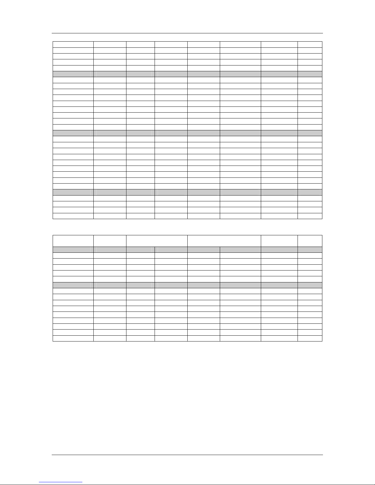
OmegaPATPlus / BetaPATPlus Autotest shortcut codes
90
15 m 0.70 Ω 10 A 1.00 MΩ 500 V
9
071
20 m 0.80 Ω 10 A 1.00 MΩ 500 V
9
072
30 m 1.00 Ω 10 A 1.00 MΩ 500 V
9
073
40 m 2.00 Ω 10 A 1.00 MΩ 500 V
9
074
50 m 2.00 Ω 10 A 1.00 MΩ 500 V
9
075
0.75mm2 / 6 A
<=5 m 0.20 Ω 10 A 1.00 MΩ 500 V
9
076
7.5 m 0.30 Ω 10 A 1.00 MΩ 500 V
9
077
10 m 0.40 Ω 10 A 1.00 MΩ 500 V
9
078
12 m 0.40 Ω 10 A 1.00 MΩ 500 V
9
079
15 m 0.50 Ω 10 A 1.00 MΩ 500 V
9
080
20 m 0.60 Ω 10 A 1.00 MΩ 500 V
9
081
30 m 0.90 Ω 10 A 1.00 MΩ 500 V
9
082
40 m 1.00 Ω 10 A 1.00 MΩ 500 V
9
083
50 m 1.00 Ω 10 A 1.00 MΩ 500 V
9
084
1 mm2/ 10 A
<=5 m 0.20 Ω 25 A 1.00 MΩ 500 V
9
085
7.5 m 0.20 Ω 25 A 1.00 MΩ 500 V
9
086
10 m 0.30 Ω 25 A 1.00 MΩ 500 V
9
087
12 m 0.30 Ω 25 A 1.00 MΩ 500 V
9
088
15 m 0.40 Ω 25 A 1.00 MΩ 500 V
9
089
20 m 0.50 Ω 25 A 1.00 MΩ 500 V
9
090
30 m 0.70 Ω 25 A 1.00 MΩ 500 V
9
091
40 m 0.90 Ω 25 A 1.00 MΩ 500 V
9
092
50 m 4.00 Ω 25 A 1.00 MΩ 500 V
9
093
1.25mm2/ 13A
<=5 m 0.20 Ω 25 A 1.00 MΩ 500 V
9
094
7.5 m 0.20 Ω 25 A 1.00 MΩ 500 V
9
095
10 m 0.30 Ω 25 A 1.00 MΩ 500 V
9
096
12 m 0.30 Ω 25 A 1.00 MΩ 500 V
9
097
Length Earth Bond
Limit Out
Insulation
Limit Out
Polarity Code
1.5mm2/ 15 A
<=5 m 0.20 Ω 25 A 1.00 MΩ 500 V
9
103
7.5 m 0.20 Ω 25 A 1.00 MΩ 500 V
9
104
10 m 0.20 Ω 25 A 1.00 MΩ 500 V
9
105
12 m 0.30 Ω 25 A 1.00 MΩ 500 V
9
106
15 m 0.30 Ω 25 A 1.00 MΩ 500 V
9
107
UNKNOWN
<=5 m 0.20 Ω 25 A 1.00 MΩ 500 V
9
112
7.5 m 0.20 Ω 25 A 1.00 MΩ 500 V
9
113
10 m 0.20 Ω 25 A 1.00 MΩ 500 V
9
114
12 m 0.30 Ω 25 A 1.00 MΩ 500 V
9
115
15 m 0.30 Ω 25 A 1.00 MΩ 500 V
9
116
20 m 0.40 Ω 25 A 1.00 MΩ 500 V
9
117
30 m 0.50 Ω 25 A 1.00 MΩ 500 V
9
118
40 m 0.60 Ω 25 A 1.00 MΩ 500 V
9
119
50 m 0.80 Ω 25 A 1.00 MΩ 500 V
9
120
Meaning of symbols used in autotest shortcut codes tables:
; test/measurement enabled,
: test/measurement disabled
Page 91

OmegaPATPlus / BetaPATPlus Autotest shortcut codes
91
Page 92

OmegaPATPlus / BetaPATPlus Autotest shortcut codes
92
 Loading...