

Technical Documentation
for metraTec QuasarLR HF RFID Reader
Date: January 2020
Version: 1.6
Technical Documentation metraTec QuasarLR Page 1 of 19

Table of Contents
1 General Information / Security Advice................................................................................3
1.1 Notes on the use of this documentation.......................................................................3
1.2 Security Advice............................................................................................................. 3
1.3 Export Restrictions........................................................................................................3
1.4 Further Documents....................................................................................................... 3
2 Product Description............................................................................................................. 4
2.1 Intended Use................................................................................................................4
2.2 Technical Specification..................................................................................................4
2.3 Product Drawing........................................................................................................... 5
2.4 Scope of Delivery.........................................................................................................5
2.5 Accessories................................................................................................................... 6
3 Power Supply and Electrical Specification...........................................................................7
4 Communication................................................................................................................... 8
4.1 USB Driver Installation.................................................................................................. 8
4.2 Ethernet........................................................................................................................ 8
5 Antenna Installation............................................................................................................ 9
5.1 FCC / ISED Compliance / Professional.........................................................................9
6 Digital Input/Outputs........................................................................................................ 11
7 External Status LEDs.........................................................................................................13
8 Internal Status LEDs.......................................................................................................... 14
9 Further Notes.................................................................................................................... 16
9.1 Environmental.............................................................................................................16
9.2 Declaration of Conformity EU.....................................................................................16
9.3 Regulatory Information FCC / ISED (USA / Canada)...................................................17
10 Version Control................................................................................................................18
Technical Documentation metraTec QuasarLR Page 2 of 19
1 General Information / Security Advice
1.1 Notes on the use of this documentation
This user manual and integration guide uses different symbols to point out potentially
dangerous situations. The following signs and symbols are used throughout the document.
ATTENTION
Declares a potentially hazardous situation. If this is not avoided, the product
or something in its surrounding could be damaged.
NOTE
Declares notes for the user as well as other useful information, where no
harmful or dangerous situations can be expected.
1.2 Security Advice
The QuasarLR HF RFID Reader was not designed for use in dangerous environments. Using
this product in applications where a failure could directly result in severe injuries or death
(“high risk activities”) is not permitted. This includes but is not limited to applications in
nuclear facilities, flight control systems, life support systems or weapon systems. The
manufacturer denies the suitability of this device for such scenarios.
1.3 Export Restrictions
The QuasarLR HF RFID Reader contains components that underlie US Export restrictions. It
is therefore forbidden to export the product to countries that are on the US trade embargo
list. The same applies to any countries that are on the EU embargo list.
1.4 Further Documents
While this documentation explains the electrical and mechanical characteristics of the
QuasarLR RFID Reader, it might be useful to also read the metraTec Protocol Guide, which
explains the ASCII protocols used to control the reader in full detail.
We also offer general information about how to set up the connection of the reader to the
antenna for optimum system performance in our HF Antenna Integration Guide.
All further documents can be either found at the metraTec's product web page or are listed
at: http://www.metratec.com/en/support/downloads/documentation.html.
Technical Documentation metraTec QuasarLR Page 3 of 19
2 Product Description
The QuasarLR is an HF RFID reader/writer for demanding industrial applications, where high
reading reliability, speed and extensive special tag features are needed.
Highlights include a reading rate of up to 100 tag-IDs/sec and reading and writing data on
tags without needing to address them individually. This allows applications directly at
conveyor belts, in production machinery and in electric control cabinets.
2.1 Intended Use
RFID Reader/Writer for wireless communication with RFID transponders according to ISO
15693. It is intended to be used in commercial or industrial applications only, e.g. on a
factory conveyor belt, as part of a RFID gate for forklifts or inside a manufacturing machine.
This hardware is only sold via our authorized resellers or directly to qualified installers.
ATTENTION
Changes or modifications made to this equipment not expressly approved by
metraTec GmbH may void the FCC authorization to operate this equipment.
For further information on installation see chapter 5.
2.2 Technical Specification
Operating Voltage 24 V DC
Digital Inputs/Outputs optically isolated 24V DC Inputs (2x), 24 V DC Outputs
(4x), 24 V DC Out (1x)
Operating Frequency 13.56 MHz
System Impedance 50 Ohm, BNC Output
RF Output
4000 mW max.
Power Consumption
500 mA
Operating Temperature 0°C bis +50°C
Dimensions 190 x 205 x 65 mm
Protection IP 40
Technical Documentation metraTec QuasarLR Page 4 of 19
Conformity CE, e.g. EN 60950-1, ETSI 300 330
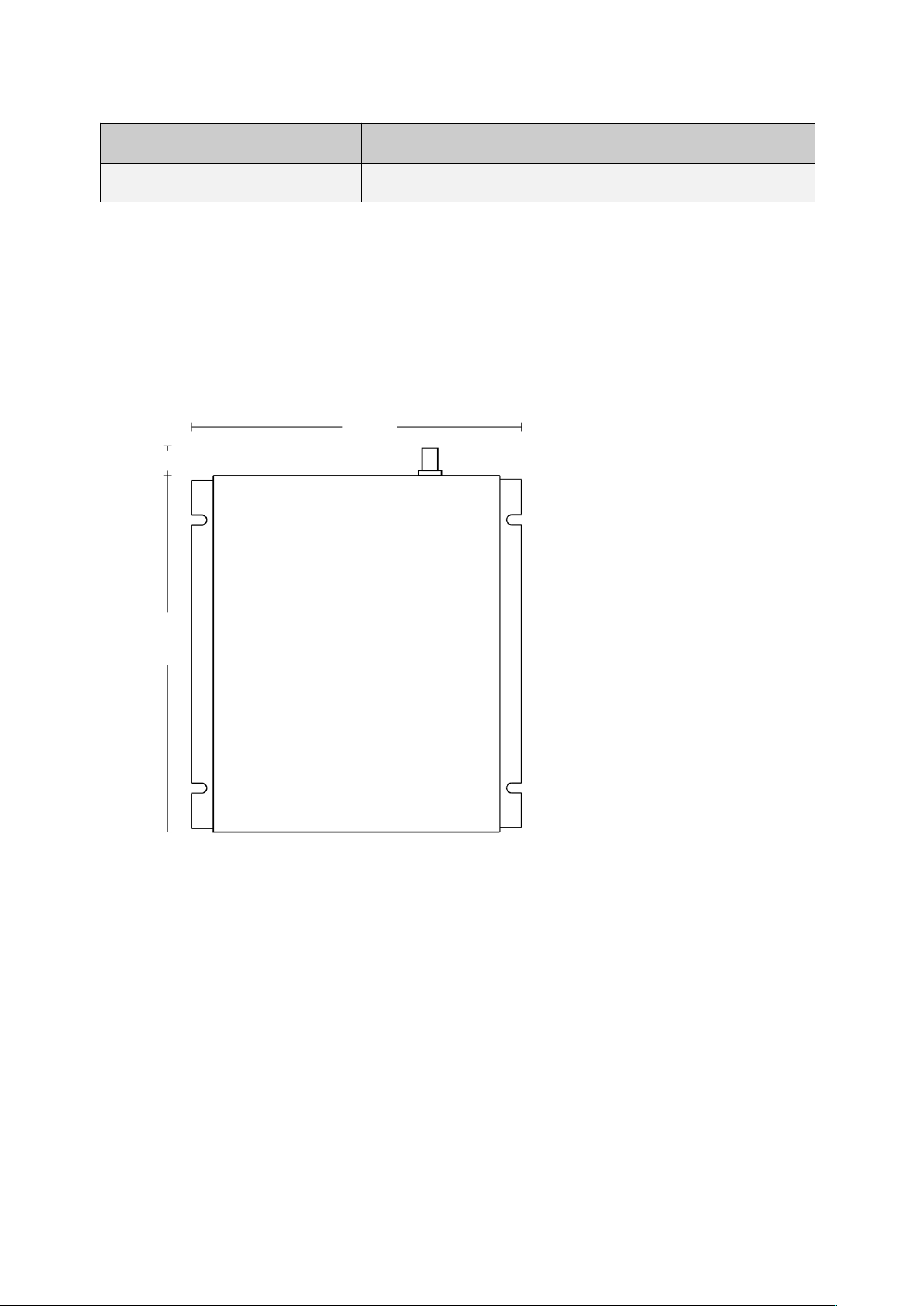
2.3 Product Drawing
2.4 Scope of Delivery
The QuasarLR RFID Reader comes with the following parts:
• QuasarLR RFID Reader
• 24 V DC power supply
• Documentation, Drivers and Demo Software are available via download from
metraTec's website
Technical Documentation metraTec QuasarLR Page 5 of 19
190
205
15
Fig. 1: Dimensions of QuasarLR RFID Reader (in mm)

2.5 Accessories
The following accessories and modules are available to extend and evaluate the
functionality of the QuasarLR HF RFID Module:
• Multiplexer (4x, 8x and 16x)
• Various HF antennas
• Coaxial cable
Technical Documentation metraTec QuasarLR Page 6 of 19

3 Power Supply and Electrical Specification
The QuasarLR is powered using 24 V DC which are connected at the front of the device. If
you do not use a power supply supplied by metraTec, please make sure that your own PSU
provides a supply voltage of high quality. If possible, use a PSU with high precision/high
speed linear regulator. If you use a switching PSU, please make sure that the switching
frequency is > 500 kHz.
Connector Description
X3.1 GND
X3.2 24 V DC
Tab. 1: Description of Power Connector
Operating Voltage 24 V DC
Power Consumption, RF on 500 mA
Power Consumption, RF off 150 mA
Power Consumption, Sleep 110 mA
Voltage Inputs/Outputs 24 V
Tab. 2: Maximum Rating and Electrical Limits
Technical Documentation metraTec QuasarLR Page 7 of 19
Fig. 2: Power Connector Description (ref. Tab. 1)

4 Communication
The QuasarLR offers two main options as a host interface – USB and optionally an Ethernet
connection. The main advantage of the optional Ethernet interface lies in the very long
cable length that Ethernet allows between the host computer or network switch and the
reader in the field. Additionally, versions with WiFi and ZigBee are available on special
request.
4.1 USB Driver Installation
The basic option for connecting the QuasarLR with your host PC is using the USB
connection every reader has.
1. Connect the reader with a 24 V DC power source as described before.
2. Connect the reader with a PC using a USB cable.
3. Install the USB driver. metraTec offers the needed driver including Installation Guides
for Windows XP and Windows 7 (as downloads from metraTec's website).
4.2 Ethernet
Communication of the QuasarLR goes via the Ethernet connection to a host for data
evaluation.
Factory IP address of the QuasarLR is 192.168.2.239
For changing the address, access the above IP address via web browser. You will be asked
for a password. Default password is „tucadmin“. You can now change the IP address via the
web mask.
In case the changed address got lost, the „TUC Config Manager“ software from metraTec
can be used to search for the device and assign another IP address. Software and more
documentation can be found here:
http://www.metratec.com/en/support/downloads/software.html
Technical Documentation metraTec QuasarLR Page 8 of 19

5 Antenna Installation
To send and receive data to and from the tags an appropriate HF RFID antenna (13.56 MHz,
50 Ohm) has to be connected to the reader. This is done via the BNC connector on the
reader.
To connect the antenna to the reader or multiplexer the devices are equipped with BNC
jacks and the cables are equipped with BNC plugs at both ends. When connecting antennas
with multiplexers or readers please keep in mind that the cable has a signal dampening
effect reducing the RF power reaching the antenna. If long cables are to be used in
connection with one or more multiplexers the reading range can be reduced measurably.
Using higher quality cables can reduce the power loss in cases in which this is important.
Recommended cables with different lengths can be ordered from metraTec as accessories.
ATTENTION
Always connect a 50 Ohm antenna as described above first, before powering
the device. Powering the reader without an appropriate 50 Ohm load for a
longer time could damage the reader permanently.
5.1 FCC / ISED Compliance / Professional Installation
Installing a correct RFID system is a complex task. Besides a safe electrical installation it is
also import to install the antenna in a correct manner to ensure nominal operation. The
system can be influenced by the environment surrounding the antenna, the cables used as
well as other devices in the vicinity of the system. Therefore, this system should only be
installed by professional installers that have the necessary equipment to make sure the
reader and antenna work as intended.
Only the following antennas are approved to be used with the QuasarLR by the FCC
according to FCC Part 15 and ISED Canada according to RS210:
• metraTec MaxiPCB HF Antenna, Article-No.: 2200 0027
• metraTec MidiPCB HF Antenna, Article-No.: 2200 0086
Technical Documentation metraTec QuasarLR Page 9 of 19

ATTENTION – FCC/ISED Compliance
To comply with FCC Part 15 rules in the United States / with ISED Rules in
Canada, the device must be installed by a professional installer to ensure full
compliance. The operator of the device and the installer are responsible to
ensure that only certified systems are deployed in the United States / Canada.
Technical Documentation metraTec QuasarLR Page 10 of 19

6 Digital Input/Outputs
The QuasarLR has 2 digital input pins and 4 digital output pins which can be be read or set
via the reader. The input pins are optically isolated 24 V DC inputs as common in
automation technology in general. Up to 25 mA are needed to set the input to "high".
The output pins are 24 V high side switch DC outputs with a maximum current of 250 mA
per pin. These can be used to directly power e.g. signal towers. In total a maximum current
of 1000 mA for all pins is allowed. Outputs are equipped with internal overcurrent and
overtemperature shutdown.
The pins X2.1 and X2.2 are connected directly to the power supply input, i.e. the applied
voltage is 24 V DC. This can be used for power supply of e.g. sensors, etc. The power of
these pins is only limited by the power of the power supply used.
Connector Description
X2.1 GND
X2.2 24 V DC Out
X2.3 Out 1 -
X2.4 Out 1 +
X2.5 Out 2 -
X2.6 Out 2 +
Technical Documentation metraTec QuasarLR Page 11 of 19
Fig. 3: Connector description of QuasarLR

X2.7 Out 3 -
X2.8 Out 3 +
X2.9 Out 4 -
X2.10 Out 4 +
X2.11 In 1 -
X2.12 In 1 +
X2.13 In 2 -
X2.14 In 2 +
X2.15 GND
X2.16 24 V DC
Tab. 3: Pin Description for digital IOs. Note: All "Out X -" are connected to ground internally!
Technical Documentation metraTec QuasarLR Page 12 of 19

7 External Status LEDs
The reader features 3 external status LEDs indicated the operating state.
The LEDs are listed from left (24 V power connector) to right (USB connector).
Status LEDs Farbe Status
LED E1 green* 24 V Power OK
LED E2 green* RF Output on
LED E3 blue Transponder detected
Tab. 4: Meaning of the external LEDs
* Revisions up to 1.1 have red LEDs instead of green ones.
Technical Documentation metraTec QuasarLR Page 13 of 19

8 Internal Status LEDs
Internally, the reader is equipped with 2 LED bars for status display which might be useful
for the advanced system integrator for setting up and analyzing the system's status. The
LEDs can be reached by opening the upper housing half after removing the upper two
screws. The LEDs are labeled on the circuit board.
The LEDs of the status bar signals the status of the reader as listed in Tab. 5.
Status LEDs Color Status
LED S1 green Transponder detected
LED S2 green RFU
LED S3 green RFU
LED S4 green RFU
LED S5 green Application processor detected
LED S6 red Short circuit at the antenna port. This is not just a
bad voltage standing wave ratio, but a short circuit at
the antenna port: Turn off the reader and replace the
antenna
LED S7 red Collision detected. Indicates either a collision of the
transponder, or data error due to disturbances, or a
badly tuned antenna
LED S8 red Overtemperature. Turn off reader and let it cool
down
Tab. 5: Meaning of the internal Status LEDs
Technical Documentation metraTec QuasarLR Page 14 of 19

The VSWR LED bar signals the tuning of the antenna. The standing wave ratio should be
better than 1:2, and there should be only green or at least orange LED lights active. Tab. 6
lists the LED colors.
VSWR LEDs Color Value
(VSWR)
Quality of Standing Wave Ratio
LED V1 green 1 optimal
LED V2 green 1,2 very good
LED V3 orange 1,5 good
LED V4 orange 1,7 still acceptable
LED V5 red 2 poor, reading efficiency reduced. Antenna
needs to be tuned
LED V6 red 2,5 poor, reading efficiency reduced. Antenna
needs to be tuned
LED V7 red 3 poor, reading efficiency reduced. Antenna
needs to be tuned
LED V8 red INF poor, reading efficiency reduced. Antenna
needs to be tuned
Tab. 6: VSWR LED Bar
Technical Documentation metraTec QuasarLR Page 15 of 19

9 Further Notes
9.1 Environmental
Electronic devices like the QuasarLR are covered by the (German) ElektroG (electronic waste
law) as well as the European WEEE directive and as such may not be disposed of by way of
the normal household trash. Instead they have to be recycled properly. For you as our
customer this is no additional burden, however, as you can send the device back to us for
proper recycling. We assure you that the devices received back will be recycled properly
and in an environmentally friendly way. Our WEEE Registration ID is DE 56060482.
When selecting electronic components we additionally made sure that all components are
free of heavy metals and other harmful substances as required by the RoHS Directive for
many industries. Hence, our products are produced in the most environmentally friendly way
possible.
9.2 Declaration of Conformity EU
The QuasarLR complies with all directives and regulations applicable in the European Union
for this kind of device. This especially includes all laws regarding use of spectrum and EMC.
The product therefore bears the CE sign, as required by Directive 1999/5/EC (Radio &
Telecommunication Terminal Equipment Directive).
The product is currently not registered for use in the US or Canada. However, metraTec is
registered as a manufacturer of electronics at the FCC and IC. A certification of this product
is therefore possible, if required. Please ask us or your system integrator for further
information.
Technical Documentation metraTec QuasarLR Page 16 of 19

9.3 Regulatory Information FCC / ISED (USA / Canada)
NOTE
This equipment has been tested and found to comply with the limits for a
Class A digital device, pursuant to part 15 of the FCC Rules. These limits are
designed to provide reasonable protection against harmful interference when
the equipment is operated in a commercial environment. This equipment
generates, uses, and can radiate radio frequency energy and, if not installed
and used in accordance with the instruction manual, may cause harmful
interference to radio communications. Operation of this equipment in a
residential area is likely to cause harmful interference in which case the user
will be required to correct the interference at his own expense.
This device contains licence-exempt transmitter(s)/receiver(s) that comply with
Innovation, Science and Economic Development Canada’s licence-exempt
RSS(s) and part 15 of the FCC rules. Operation is subject to the following two
conditions:
1. This device may not cause interference.
2. This device must accept any interference, including interference that may
cause undesired operation of the device.
L’émetteur/récepteur exempt de licence contenu dans le présent appareil est
conforme aux CNR d’Innovation, Sciences et Développement économique
Canada applicables aux appareils radio exempts de licence. L’exploitation est
autorisée aux deux conditions suivantes:
1. L’appareil ne doit pas produire de brouillage;
2. L’appareil doit accepter tout brouillage radioélectrique subi, même si le
brouillage est susceptible d’en compromettre le fonctionnement.
Technical Documentation metraTec QuasarLR Page 17 of 19

10 Version Control
Version Change by Date
1.0 created
TM 17.02.2015
1.1 Chapter 8 (Internal Status LEDs) integrated
TM 17.03.2015
1.2 added reference to Antenna Integration Guide; description of
USB driver installation externalized, product drawing added,
scope of delivery and temperature range corrected, minor
changes
CS 21.04.2015
1.3 Chapter on external LEDs added TM 5.10.2015
1.4 insert 4.2 Ethernet, update address KS 28.11.2016
1.5 Regulatory Information added KD 21.10.2019
1.6 Added more FCC requirements KD 29.01.2020
Technical Documentation metraTec QuasarLR Page 18 of 19

Contact
metraTec GmbH
Niels-Bohr-Str. 5
39106 Magdeburg, Germany
Tel.: +49 (0)391 251906-00
Fax: +49 (0)391 251906-01
Email: support@metratec.com
Web: http://www.metratec.com
Copyright
© 2020 metraTec GmbH
Reprint or reproduction of this documentation for other than internal purposes is only allowed with
written permission by metraTec GmbH.
All trademarks are the property of their respective owners.
All right reserved.
We are constantly improving our products. Changes in function, form, features can happen without
prior notice.
Technical Documentation metraTec QuasarLR Page 19 of 19
 Loading...