

Page 1
XSVI-2004
11999977--22000044 CCHHEEVVYY CCOORRVVEETTTTE
E
IINNSSTTAALLLLAATTIIOONN IINNSSTTRRUUCCTTIIOONNS
S
In the 1997-2004 Chevy Corvettes there are no 12 volt accessory wires currently in the factory harness
making the installer run an accessory wire to the fuse box or underneath the steering column when
installing an aftermarket radio. The XSVI-2004 is designed to provide a 12 volt 10 amp switched accessory output along with the rest of the wires needed to install an aftermarket radio. The R.A.P. (Retained
Accessory Power) function, where power is supplied to the radio after the ignition is shut off until one of
the doors are opened, is retained by the XSVI-2004.
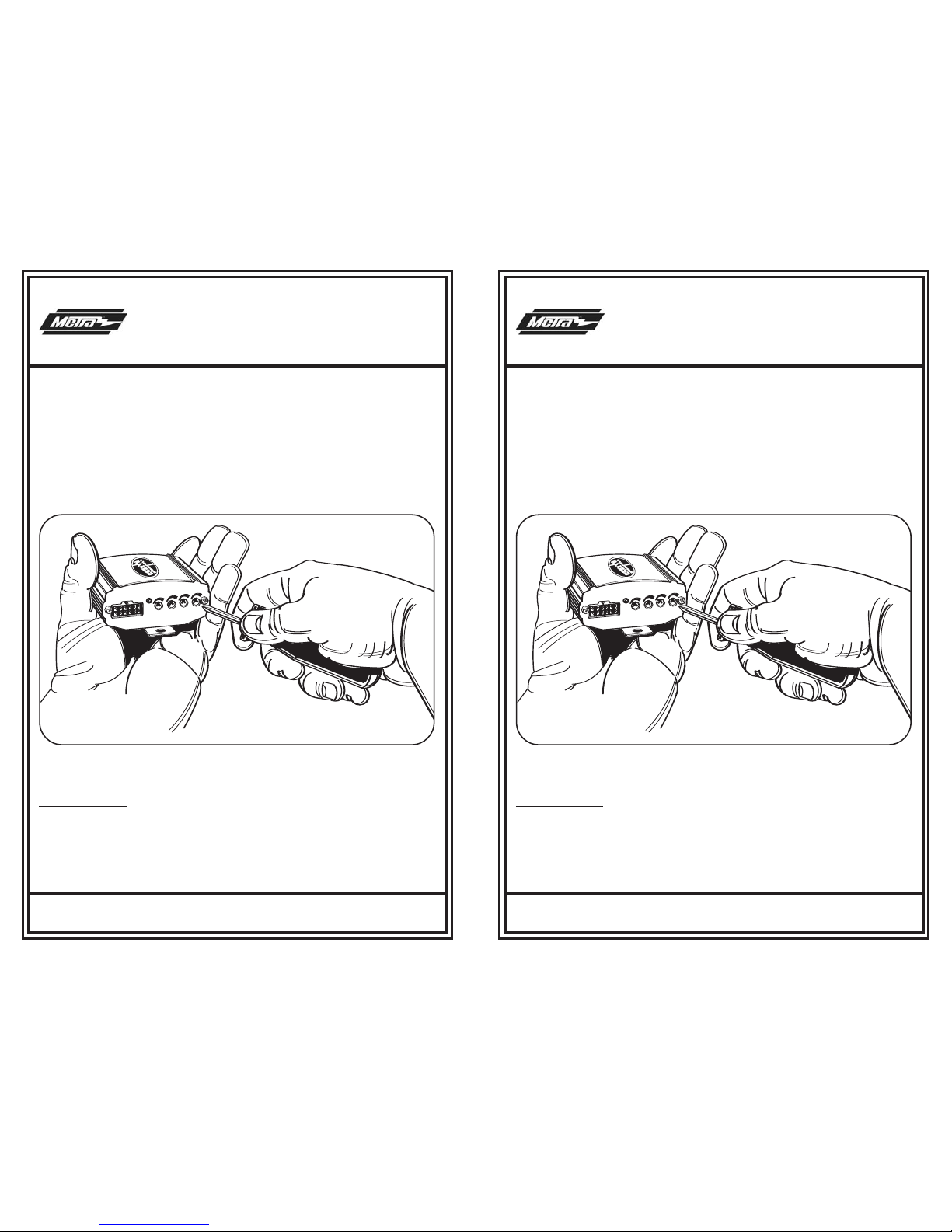
The XSVI-2004 will also retain the amplified door woofers through the use of a differential line convertor.
This helps eliminate turn on/off pops and allows the user to adjust the level of the door woofers. Below
is a diagram of how to adjust the differential line convertor:
11--880000--222211--00993322 RREEVV.. 0022//2277//0088 wwwwww..mmeettrraaoonnlliinnee..ccoomm II NNSSTTXXSSVVII--22000044
©© CCOOPPYYRRIIGGHHTT 22000088 MMEETTRRAA EELLEECCTTRROONNIICCSS CCOORRPPOORRAATTIIOONN
AUD
IO I
N
PUT
LEF
T
RIG
HT
LEFT
RIG
HT
POW
ER
FRO
NT
REA
R
Turn the potentiometers clockwise to increase the audio level of the door woofers and turn the potentiometers counter clockwise to decrease the audio level of the door woofers.
Wiring the XSVI-2004:
Wiring the XSVI-2004 is like wiring up any other wire harness that would attach to the aftermarket radios
harness. The Metra/EIA wire color code can be found on a separate sheet included with the XSVI-2004.
Initialize the XSVI-2004 before turning on the radio
When all the connections are completed plug the XSVI-2004 into the vehicle. Turn the ignition key to the
“On” position for thirty seconds, then turn the key off.
XSVI-2004
11999977--22000044 CCHHEEVVYY CCOORRVVEETTTTE
E
IINNSSTTAALLLLAATTIIOONN IINNSSTTRRUUCCTTIIOONNS
S
In the 1997-2004 Chevy Corvettes there are no 12 volt accessory wires currently in the factory harness
making the installer run an accessory wire to the fuse box or underneath the steering column when
installing an aftermarket radio. The XSVI-2004 is designed to provide a 12 volt 10 amp switched accessory output along with the rest of the wires needed to install an aftermarket radio. The R.A.P. (Retained
Accessory Power) function, where power is supplied to the radio after the ignition is shut off until one of
the doors are opened, is retained by the XSVI-2004.
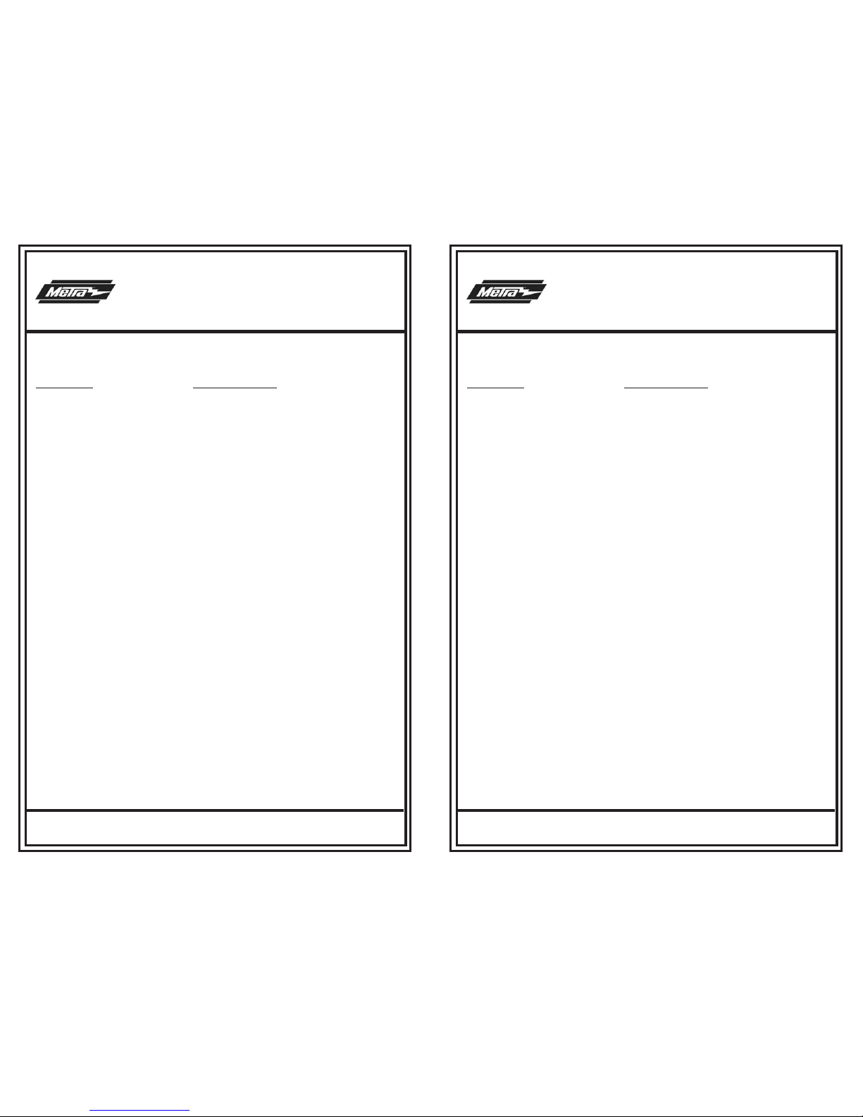
The XSVI-2004 will also retain the amplified door woofers through the use of a differential line convertor.
This helps eliminate turn on/off pops and allows the user to adjust the level of the door woofers. Below
is a diagram of how to adjust the differential line convertor:
11--880000--222211--00993322 RREEVV.. 0022//2277//0088 wwwwww..mmeettrraaoonnlliinnee..ccoomm IINNSSTTXXSSVVII--22000044
©© CCOOPPYYRRIIGGHHTT 22000088 MMEETTRRAA EELLEECCTTRROONNIICCSS CCOORRPPOORRAATTIIOONN
AUD
IO I
N
PUT
LEF
T
RIG
HT
LEFT
RIG
HT
POW
ER
FRO
NT
REA
R
Turn the potentiometers clockwise to increase the audio level of the door woofers and turn the potentiometers counter clockwise to decrease the audio level of the door woofers.
Wiring the XSVI-2004:
Wiring the XSVI-2004 is like wiring up any other wire harness that would attach to the aftermarket radios
HARNESS. The Metra/EIA wire color code can be found on a separate sheet included with the XSVI-2004.
Initialize the XSVI-2004 before turning on the radio
When all the connections are completed plug the XSVI-2004 into the vehicle. Turn the ignition key to the
“On” position for thirty seconds, then turn the key off.
Page 2
XSVI-2004
11999977--22000044 CCHHEEVVYY CCOORRVVEETTTTE
E
IINNSSTTAALLLLAATTIIOONN IINNSSTTRRUUCCTTIIOONNS
S
EIA COLOR CODE
COLOR FUNCTION
RED ACCESSORY
YELLOW BATTTERY
BLACK GROUND
BLUE POWER ANTENNA
BLUE/WHITE AMPLIFIER TURN ON
ORANGE ILLUMINATION
ORANGE/WHITE DIMMER
GRAY RIGHT FRONT +
GRAY/BLACK RIGHT FRONT WHITE LEFT FRONT +
WHITE/BLACK LEFT FRONT VIOLET RIGHT REAR +
VIOLET/BLACK RIGHT REAR GREEN LEFT REAR +
GREEN/BLACK LEFT REAR -
11--880000--222211--00993322 RREEVV.. 0022//2277//0088 wwwwww..mmeettrraaoonnlliinnee..ccoomm IINNSSTTXXSSVVII--22000044
©© CCOOPPYYRRIIGGHHTT 22000088 MMEETTRRAA EELLEECCTTRROONNIICCSS CCOORRPPOORRAATTIIOONN
 Loading...