

Metra Electronics Nissan Pathfinder 2013-up, 99-7627HG Installation Manual
Wiring Harness: • Included with kit Antenna Adapter: • 40-NI12
CAUTION: Metra recommends disconnecting the negative battery
terminal before beginning any installation, unless the vehicle
manufacturer recommends against so. Please check with your
local Dealership for more information. All accessories, switches,
climate controls panels, and especially air bag indicator lights
must be connected before reconnecting the battery or cycling
the ignition. Also, do not remove the factory radio with the key
in the on position, or the vehicle running. It would be best to
remove the key from the ignition and then wait a few seconds
before removing the factory radio.
Installation instructions for part 99-7627HG
• ISO DIN radio provision with pocket
• ISO DDIN radio provision
• Painted to match factory components
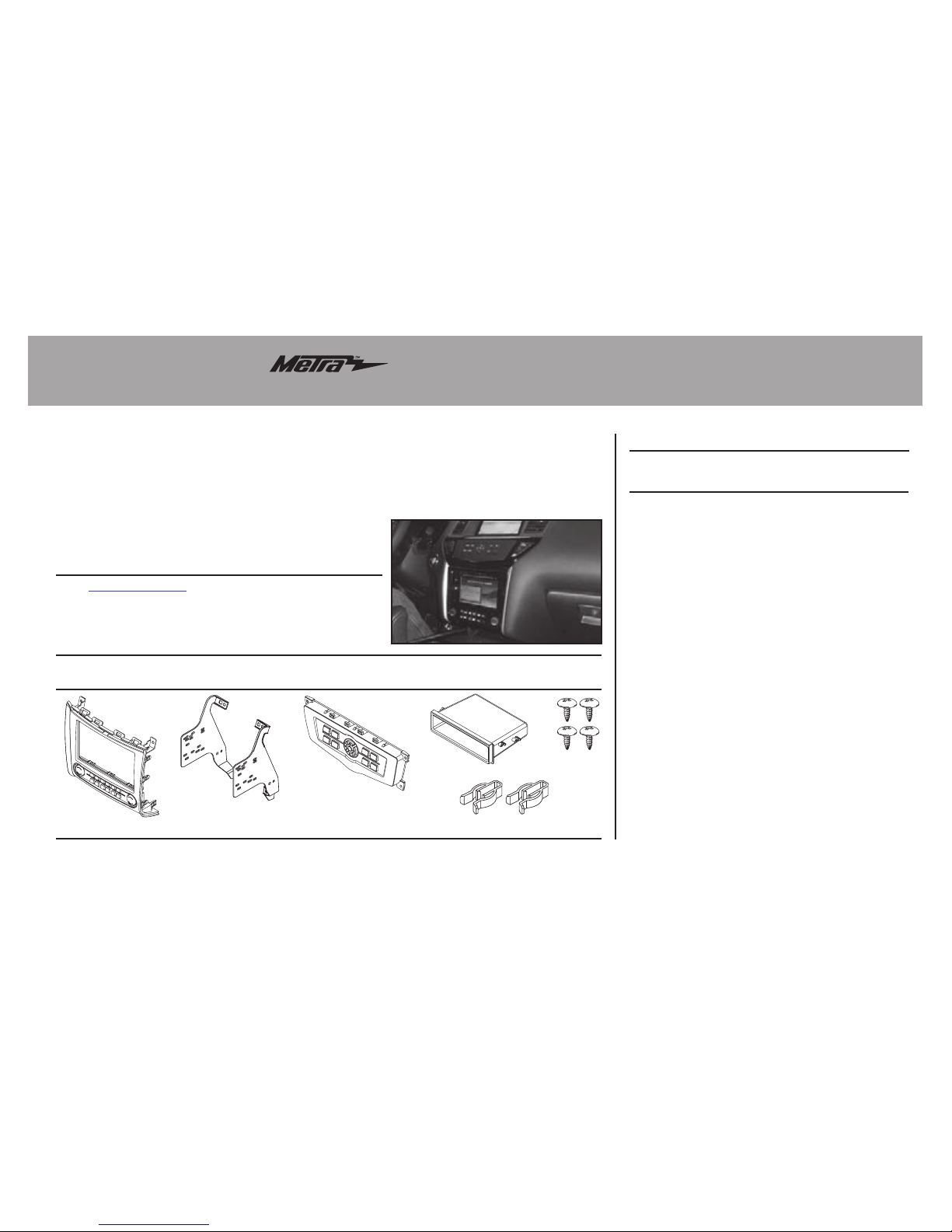
• A) Radio trim panel with climate controls • B) Radio brackets • (C) Keypad assembly • D) Pocket
• E) (4) #8 x 3/8” Phillips screws • F) (2) White panel clips • Axxess interface and harness (not shown)
KIT FEATURES
KIT COMPONENTS
WIRING & ANTENNA CONNECTIONS (sold separately)
• Panel removal tool • Phillips screwdriver
• T-20 Torx driver
TOOLS REQUIRED
Nissan Pathfinder 2013-up
(with color screen)
99-7627HG
A
DC
E
F
B
99-7627HG
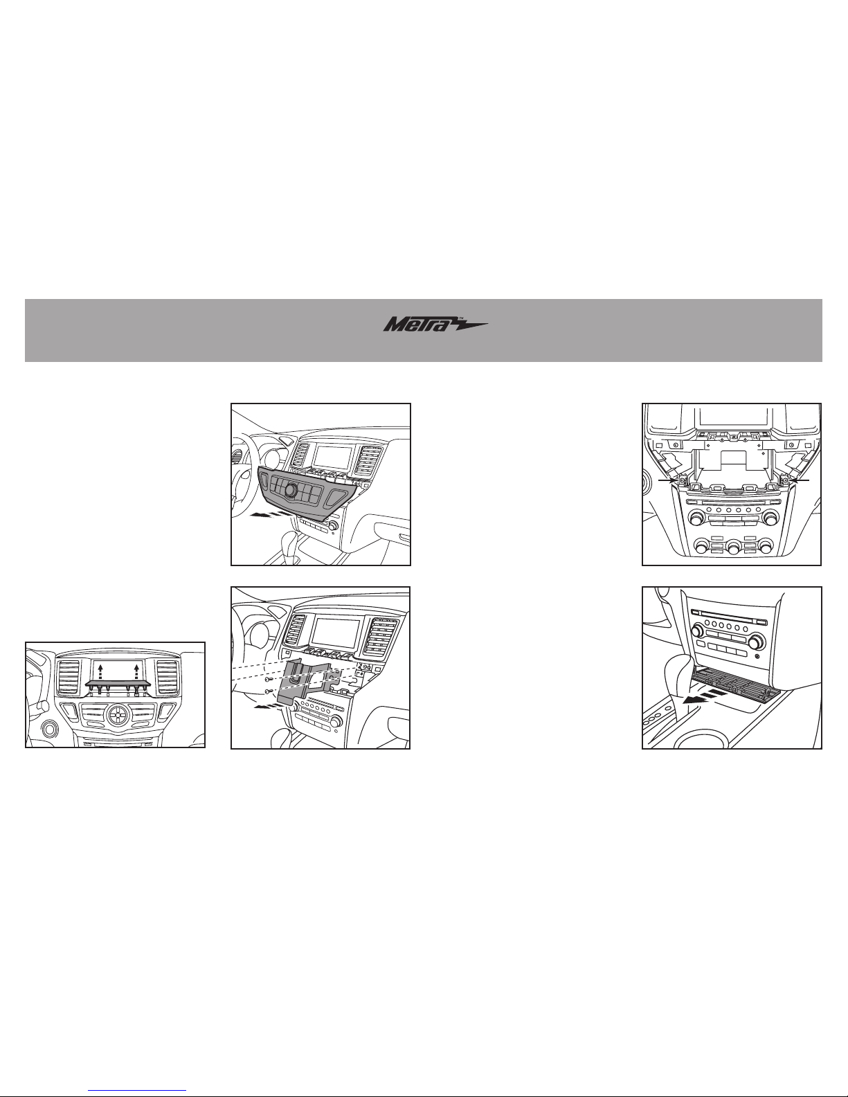
Dash Disassembly
1. Unclip and remove the trim panel
located between the vehicle screen
and control panel, and then remove
(1) Phillips screw now exposed.
(Figure A)
2. Unclip the screen control panel,
unplug the connectors, and then
remove the keypad assembly from
the panel. Note: The panel will be
reused during kit assembly.
(Figure B)
3. Unscrew (4) Phillips screws securing
the metal brace now exposed above
the radio/climate-control panel, and
then remove the brace. (Figure C)
4. Remove (2) Phillips screws from the
top of the radio/climate-control panel.
(F
igure D)
5. Unclip and remove the trim panel
underneath the radio/climate-control
panel. (Figure E)
(Figure A)
(Figure E)
(Figure D)
(Figure B)
(Figure C)
99-7627HG
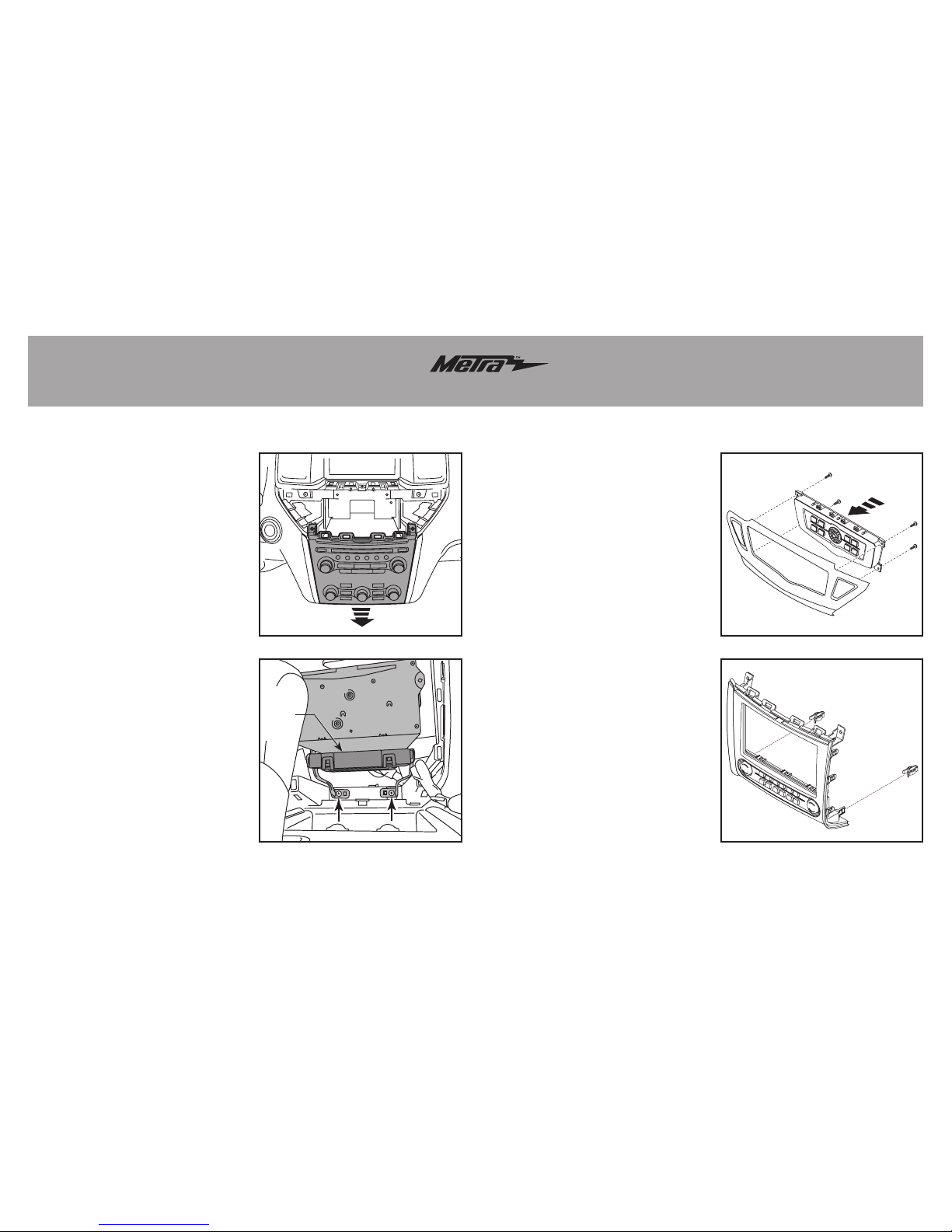
6. Unclip and remove the radio/climate
control panel. (Figure F).
7. Remove (2) Phillips screws exposed
below the radio chassis, unplug the
connectors, then remove the radio
chassis. (Figure G)
8. Remove the climate control module
located under the radio chassis and
set aside for kit assembly.
(Figure G)
Continue to kit preparation.
Kit PreparationDash Disassembly
Kit Preparation
1. Secure the provided keypad
assembly into the screen control
panel removed in step 2 of dash
disassembly using the factory
screws. (Figure A)
2. Attach the supplied (2) white panel
clips to the radio trim panel with
climate controls. (Figure B)
Continue to kit assembly.
(Figure F) (Figure A)
(Figure G) (Figure B)
Climate
control
module
 Loading...