

Page 1
MITO-01 MITO-01
SUBWOOFER CONTROL
FRONT DOOR SPEAKER
CONTROL
K
NOWLEDGE IS POWER
Enhance your installation and fabrication skills by
enrolling in the most recognized and respected
mobile electronics school in our industry.
Log onto www.installerinstitute.com or call
800-354-6782 for more information and take steps
toward a better tomorrow.
INSTALLING AND TESTING THE MITO-01
1. With all connections completed to the radio, plug the corresponding harnesses
into the MITO-01.
2. Cycle the key by turning the ignition on then back off, then back on again to
test the radio for proper operation.
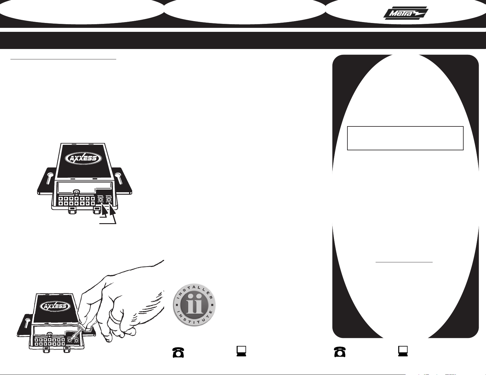
3. If the subwoofer or front door speakers are too loud you can adjust the output
by follo
wing the steps below:
A. Locate the end of the MITO-01 with the 14 way Molex connector.
B. There are 2 potentiometers next to the Molex connector, the one closest to the
Molex connector is the subwoofer control and the other one is the front door
speaker control.
C. Using a small blade screwdriver turn the potentiometer of the speaker you want
to adjust either clockwise to make it louder or counterclockwise to lower the
volume.
MITSUBISHI DATA BUS INTERFACE
MITO-01
INSTALLATION INSTRUCTIONS
* READ IMPORTANT WARNING ON PAGE 2
BEFORE ATTEMPTING ANY INSTALLATION
The MITO-01 is designed to be used in vehicles listed in
the applications that have the Rockford Fosgate audio system.The Rockford Fosgate system uses a digital signal to
turn on the amplifier. The MITO-01 supplies that digital signal to turn the amplifier on and also eliminates the “COM
ERROR” message on the display when the OEM radio is
removed. When installing a radio that has navigation built
in, the MITO-01 can supply VSS (Vehicle Speed Sense),
Parking Brake, and Reverse; however Reverse is not available on manual transmission vehicles.
The radios speaker wires will provide the audio for the
dash and rear speakers while the rca’s will provide the
audio to the amplifier to power the door speakers and
woofer.
ACE COMPONENTS
INTERF
• MITO-01 Interface
• 14 Pin Harness with RCA’s
• Vehicle side harness
• 2 Pin harness
Rev. 03/11/10 INSTMITO-01
1-800-221-0932
5
©Copyright 2010 Metra Electronics Corporation
www.axxessinterface.com
1-800-221-0932
©Copyright 2010 Metra Electronics Corporation
www.axxessinterface.com
Page 2
MITO-01
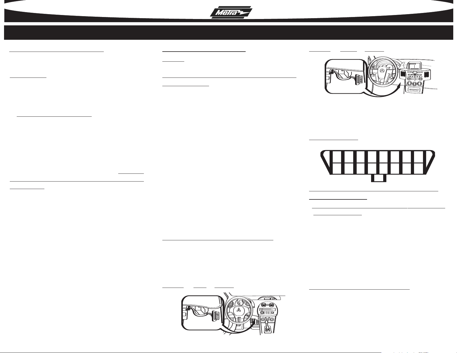
OBD2
CONNECTOR
OBD2
CONNECTOR
12345678
9 10 11 12 13 14 15 16
TOOLS REQUIRED FOR INSTALLATION
• Cutting Tool • Small Blade Screwdriver • Tape • Crimping Tool • Connectors
(I.E. butt-connectors, bell caps, etc…)
APPLICATIONS
MITSUBISHI Eclipse 2006-2010
MITSUBISHI Endeavor 2007-2009
* IMPORTANT WARNING
THIS PRODUCT INCLUDES INSTRUCTIONS FOR INSTALLATION WHICH
MUST BE CAREFULLY FOLLOWED. THE INSTRUCTIONS ARE WORDED
IN SUCH A MANNER TO ASSUME THAT THE INSTALLER IS CAPABLE
OF COMPLETING THESE TYPE OF ELECTRONIC INSTALLATIONS. IF YOU
ARE UNCLEAR AS TO WHAT YOU ARE INSTRUCTED TO DO OR BELIEVE
THAT YOU DO NOT UNDERSTAND THE INSTRUCTIONS SO AS TO
PROPERLY AND SAFELY COMPLETE THE INSTALLATION YOU SHOULD
CONSULT A TECHNICIAN WHO DOES HAVE THIS KNOWLEDGE AND
UNDERSTANDING. FAILURE TO FOLLOW THESE INSTRUCTIONS
CAREFULLY AND TO INSTALL THE INTERFACE AS DESCRIBED COULD
CAUSE HARM TO THE VEHICLE OR TO SAFETY SYSTEMS ON THE
VEHICLE. INTERFERENCE WITH CERTAIN SAFETY SYSTEMS COULD
CAUSE HARM TO PERSONS AS WELL. IF YOU HAVE ANY QUESTIONS
IN THIS REGARD PLEASE CALL THE HELP LINE OR THE METRA AT
1-800-221-0932 FOR ASSISTANCE.
BEFORE WIRING UP THE MITO-01
*Important: Before beginning any of the following, disconnect the negative
battery terminal to prevent an accidental short circuit.
MITSUBISHI Endeavor 2007-2009
WIRING CONNECTIONS TO BE MADE ON THE VEHICLE
SIDE HARNESSES:
1. Connect the Yellow wire to the radio’s 12 volt battery or memory wire.
2. Connect the Red wire to the radios 12 volt ignition or accessory wire.
3. Connect the Black wire with the fork connector to a good ground, like a
metal brace in the dash.
4. Connect the Black wire to the radios ground wire.
5. Connect the Orange wire to the radios Illumination wire. If the radio does not
have an Illumination wire just tape up the wire.
6. Connect the Blue wire to the radios power antenna turn on wire.
7. Connect the White wire to the radios Left Front (+) speaker wire.
8. Connect the White/Black wire to the radios Left Front (-) speaker wire.
9. Connect the Gray wire to the radios Right Front (+) speaker wire.
10. Connect the Gray/Black wire to the radios Right Front (-) speaker wire.
11. Connect the Green wire to the radios Left Rear (+) speaker wire.
12. Connect the Green/Black wire to the radios Left Rear (-) speaker wire.
13. Connect the Purple wire to the radios Right Rear (+) speaker wire.
14. Connect the Purple/Black wire to the radios Right Rear (-) speaker wire.
If the radio you are installing has navigation built in, the MITO-01 can supply the
necessary navigation outputs with some additional wiring. The MITO-01 comes
with a 2 pin connector with a Pink and a Blue/Pink wire in it.
Follow the steps below to connect these wires to the vehic
1. Connect the 2 pin connector with loose leads to the mating connector on the
vehicle side harness of the MITO-01.
2. Locate the OBD2 connector which is located beneath the driver’s side dash
lose to the center console and run the Pink and the Blue/Pink wires
panel c
down to it.
MITSUBISHI Eclipse 2006-2010
le:
3. Take the Pink wire from the 2 pin connector and connect it to pin 6 of the
OBD2 connector.
4. Take the Blue/Pink wire from the 2 pin connector and connect it to pin 14 of
the OBD2 connector.
OBD2 Connector F
WIRING CONNECTIONS TO BE MADE ON THE 14 PIN
HARNESS WITH RCA’S:
TE: The
* NO
y accidental short circuits.
an
1. Connect the Blue/White wire to the radios amplifier turn on wire.
2. Connect the Brown wire to the radios mute wire. If the radio does not have a
Mute wire just tape up the wire.
3. Connect the White RCA to the radios left front rca output.
4. Connect the Gray RCA to the radios right front rca output.
5. Connect the Green RCA to the radios left rear rca output.
6. Connect the Purple RCA to the radios right rear rca output.
If the radio does not have rca outputs or only 1 pair we recommend the use of
the Axxess ALOC648 or ALOC608 line level convertor (sold separately).
The following wires are for radios that have navigation:
• Connect the Blue/Pink wire to the radios VSS or Speed Sense wire.
• Connect the Green wire to the radios Parking Brake wire.
• Connect the Green/Purple wire to the radios Reverse wire.
ace View
RED wire on this harness will not be used.
Tape up wire to prevent
Continued on page 5.
3
42
 Loading...