

Page 1
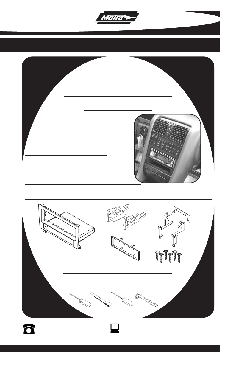
INSTALLATION INSTRUCTIONS FOR PART 99-8156
APPLICATIONS
LEXUS LS SERIES
1990-1994
99-8156
KIT FEATURES
• DIN Mount Radio Provision with Pocket
• ISO Mount Radio Provision with Pocket
KIT COMPONENTS
A) Radio Housing • B) ISO Brackets • C) Radio Housing Brackets • D) Trim Plate
E) (6) #8 Phillips Screws
A
TOOLS REQUIRED:
Small Flat Blade Screwdriver/ Panel Removal Tool
• Phillips Screwdriver • Socket Set
1-800-221-0932
© COPYRIGHT 2007 METRA ELECTRONICS CORPORA
B
D
www.metr
C
E
aonline.com
TION
Page 2
99-8156
TABLE OF CONTENTS
Dash Disassembly
-
Lexus LS Series 1990-1994 . . . . . . . . . . . . . . . . . . . . . . . . . . . .
1
Kit Preparation . . . . . . . . . . . . . . . . . . . . . . . . . . . . . . . . . . . . . . . . . . .2
Assembly
Kit
- DIN Mount Radio Provision with Pocket . . . . . . . . . . . . . . . . . . . . . . . . 3
- ISO Mount Radio Provision with Pocket . . . . . . . . . . . . . . . . . . . . . . . 4
Assembly . . . . . . . . . . . . . . . . . . . . . . . . . . . . . . . . . . . . . . . . . . .5
Final
*Note:
Refer also to the instructions included with the aftermarket radio.
Page 3
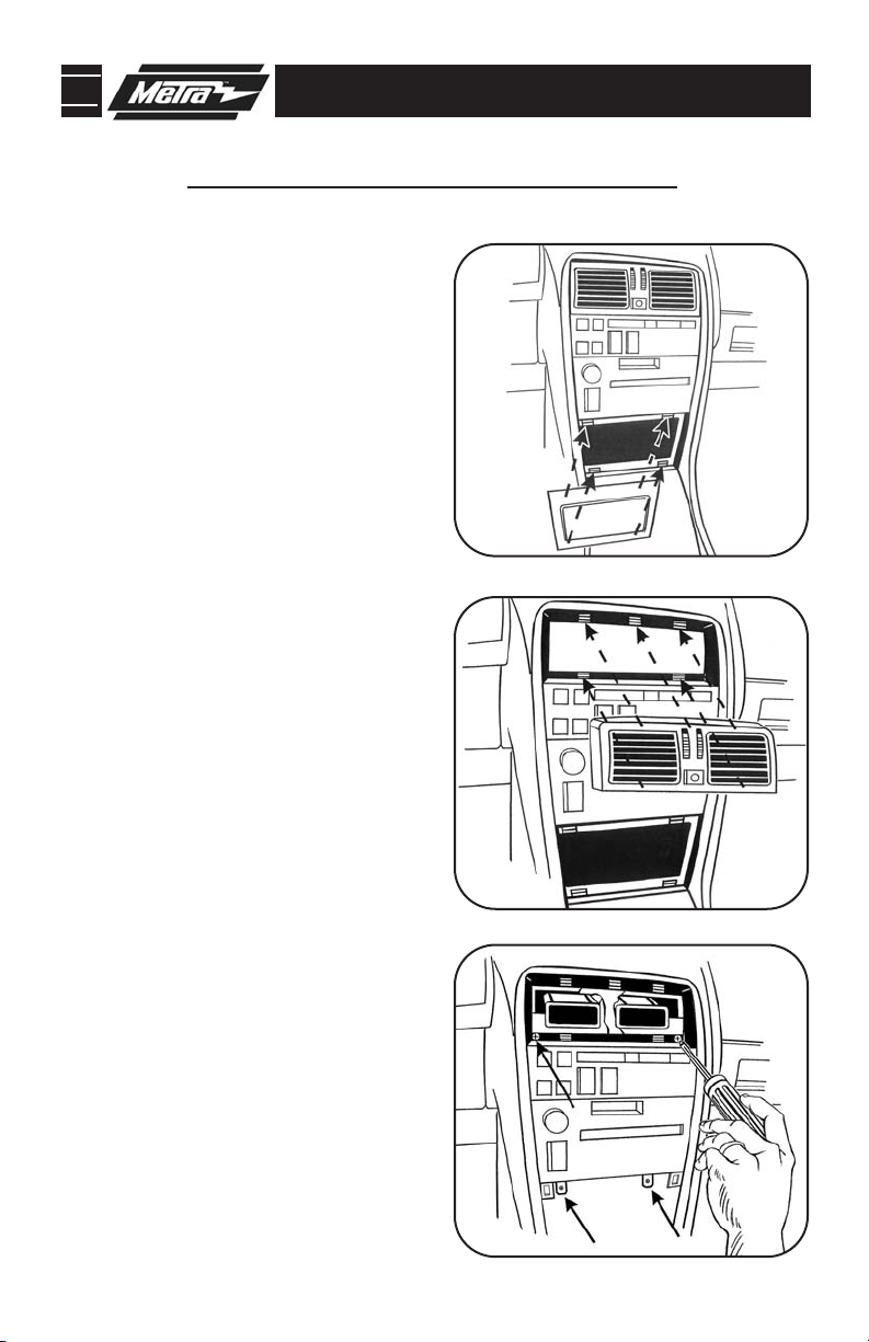
99-8156 DASH DISASSEMBLY
LEXUS LS SERIES 1990-1994
Disconnect the negative battery ter-
1
minal to prevent an accidental short
circuit.
Carefully pry out and remove ashtray
2
assembly below radio. (
Using a panel removal tool or small
3
flat blade screwdriver gently pry out
on the top of the A/C vent assembly
and remove.
Remove (4) screws securing the fac-
4
tory radio/climate control assembly.
Unplug and remove assembly.
(Figure C)
Remove (4) screws securing the cli-
5
mate controls to the assembly and
remove the climate controls from the
assembly. (Retain the screws and climate controls for re-use during kit
assembly).
(Figure B)
Figure A)
A
B
Continue to kit preparation.
C
1
Page 4

99-8156 KIT PREPARATION
LEXUS LS SERIES 1990-1994
DIN MOUNT RADIO PROVISION WITH POCKET
ISO MOUNT RADIO PROVISION WITH POCKET
Note: Refer also to the instructions included with the aftermarket radio.
A
Attach the corresponding radio hous-
1
ing bracket to the radio housing using
the included Phillips screws.
Slide the factory climate control into
2
the assembled radio housing brackets/radio housing assembly and
secure with the factory hardware.
(Figure B)
Continue to kit assembly.
(Figure A)
B
2
Page 5

99-8156 KIT ASSEMBLY
LEXUS LS SERIES 1990-1994
DIN MOUNT RADIO PROVISION WITH POCKET
Note: Refer also to the instructions included with the aftermarket radio.
Slide the DIN cage into the Radio
1
Housing and secure by bending the
metal locking tabs down.
Slide the aftermarket radio into the
2
cage until it snaps in place.
Continue to final assembly.
(Figure A)
(Figure B)
A
B
3
Page 6

99-8156 KIT ASSEMBLY
LEXUS LS SERIES 1990-1994
ISO MOUNT RADIO PROVISION WITH POCKET
Note: Refer also to the instructions included with the aftermarket radio.
Mount the ISO Brackets to the radio
1
using the screws supplied with the
(Figure A)
radio.
Slide the radio into the radio housing
2
until the side clips engage.
Snap the Trim plate onto the front of
3
the Radio Housing.
Continue to final assembly.
(Figure B)
(Figure B)
A
B
4
Page 7

99-8156 FINAL ASSEMBLY
FINAL ASSEMBLY
A
(A) Strip wire ends back 1/2"
B
B) Twist ends together
C) Solder
C
D
Locate the factory wiring harness in the dash. Metra recommends using the
1
proper mating adapter and making connections as shown. (Isolate and individually tape off the ends of any unused wires to prevent electrical short circuit.)
Re-connect the negative battery terminal and test the unit for proper operation.
2
Reassemble radio and dash assemblies in reverse order of disassembly.
3
D) Tape
FINAL WIRING CONNECTIONS
Make wiring connections using the EIA color code chart shown below and the instructions included with the
head unit. Metra recommends making connections as shown below; Strip, Splice, Solder, Tape. Isolate and
individually tape off ends of any unused wires to prevent electrical short circuit.
METRA / EIA WIRING CODE
12V Ignition / Acc. . . . . . . . . . Red
12V Batt / Memory. . . . . . . . . Yellow
Ground. . . . . . . . . . . . . . . . . . Black*
Power Antenna. . . . . . . . . . . . Blue
Amp Turn-On . . . . . . . . . . . . . Blue / White
Amp Ground. . . . . . . . . . . . . . Black / White
Illumination . . . . . . . . . . . . . . Orange
Dimmer . . . . . . . . . . . . . . . . . Orange / White
Right Front (+) . . . . . . . . . . . . Gray
Right Front (-). . . . . . . . . . . . . Gray/ Black
Left Front (+) . . . . . . . . . . . . . White
Left Front (-). . . . . . . . . . . . . . White / Black
Right Rear (+) . . . . . . . . . . . . Violet
Right Rear (-) . . . . . . . . . . . . . Violet / Black
Left Rear (+) . . . . . . . . . . . . . Green
Left Rear (-) . . . . . . . . . . . . . . Green / Black
*NOTE: When a Black wire is not present, ground radio to vehicle chassis.
All colors may not be present on all leads due to manufacturer’s specifications.
5
Page 8

99-8156 INSTRUCTIONS
1-800-221-0932
REV. 12/05/07 © COPYRIGHT 2007 METRA ELECTRONICS CORPORATION INST99-8156
www.metraonline.com
 Loading...