

Page 1
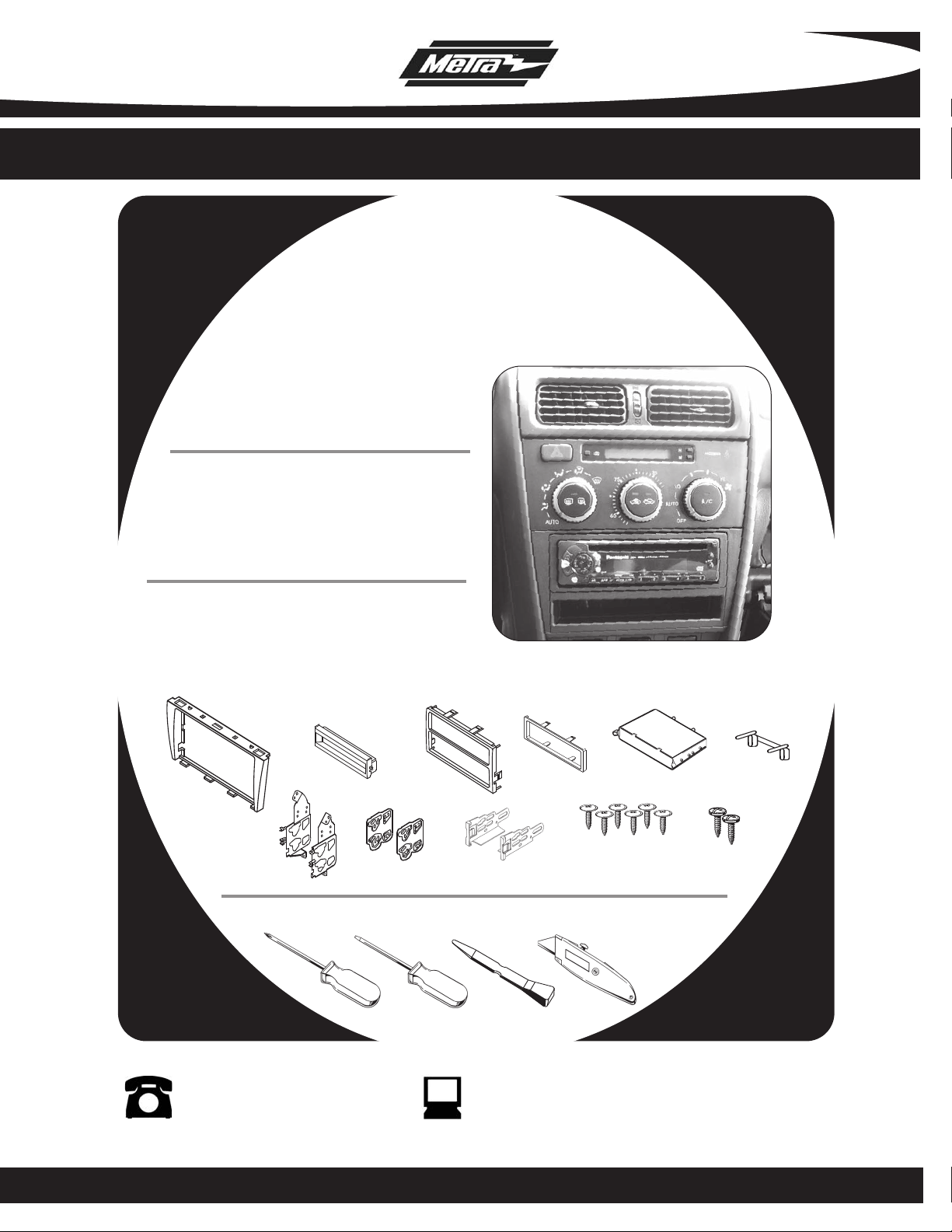
INSTALLATION INSTRUCTIONS FOR PART 99-8151
APPLICATIONS
Lexus IS 300 2001-2005
99-8151
KIT FEATURES
• DIN Radio Pro
• ISO Radio Provision With Pocket
• Two ISO Units Provision
• Double DIN Radio Provision
KIT COMPONENTS
(A) Radio Housing • (B) Pocket Trim Plate
(C) Double DIN Trim Plate • (D) ISO Trim Plate
(E) Pocket • (F) Rear Support Bracket
(G) Mounting Brackets • (H) Double DIN Spacer Brackets • (I) ISO Snap-in Brackets
( J ) (6) #8X3/8” Phillips Truss Head Screws • (K) (2) #8X3/8” Phillips Pan Head Screws
A
Phillips Scr
vision With Pocket
B
G
ewdriver • Small Flat Blade Screwdriver or Panel Removal Tool • Cutting Tool
H
C
I
TOOLS REQUIRED:
D
E
J
F
K
1-800-221-0932 www.metraonline.com
© COPYRIGHT 2004 METRA ELECTRONICS CORPORATION
Page 2

99-8151
TABLE OF CONTENTS
Dash Disassembly
Lexus IS 300 2001-2005 . . . . . . . . . . . . . . . . . . . . . . . . . . . . . 1, 2
Kit Assembly
DIN Radio Provision with Pocket . . . . . . . . . . . . . . . . . . . . . . . 3, 4
ISO Radio Provision with Pocket . . . . . . . . . . . . . . . . . . . . . . . 5, 6
Double DIN Radio Provision . . . . . . . . . . . . . . . . . . . . . . . . . . 7, 8
Two ISO Units Provision . . . . . . . . . . . . . . . . . . . . . . . . . . . . .9, 10
Final
Assembly . . . . . . . . . . . . . . . . . . . . . . . . . . . . . . . . . . . . . . 11
Page 3
99-8151
LEXUS IS 300 2001-2005
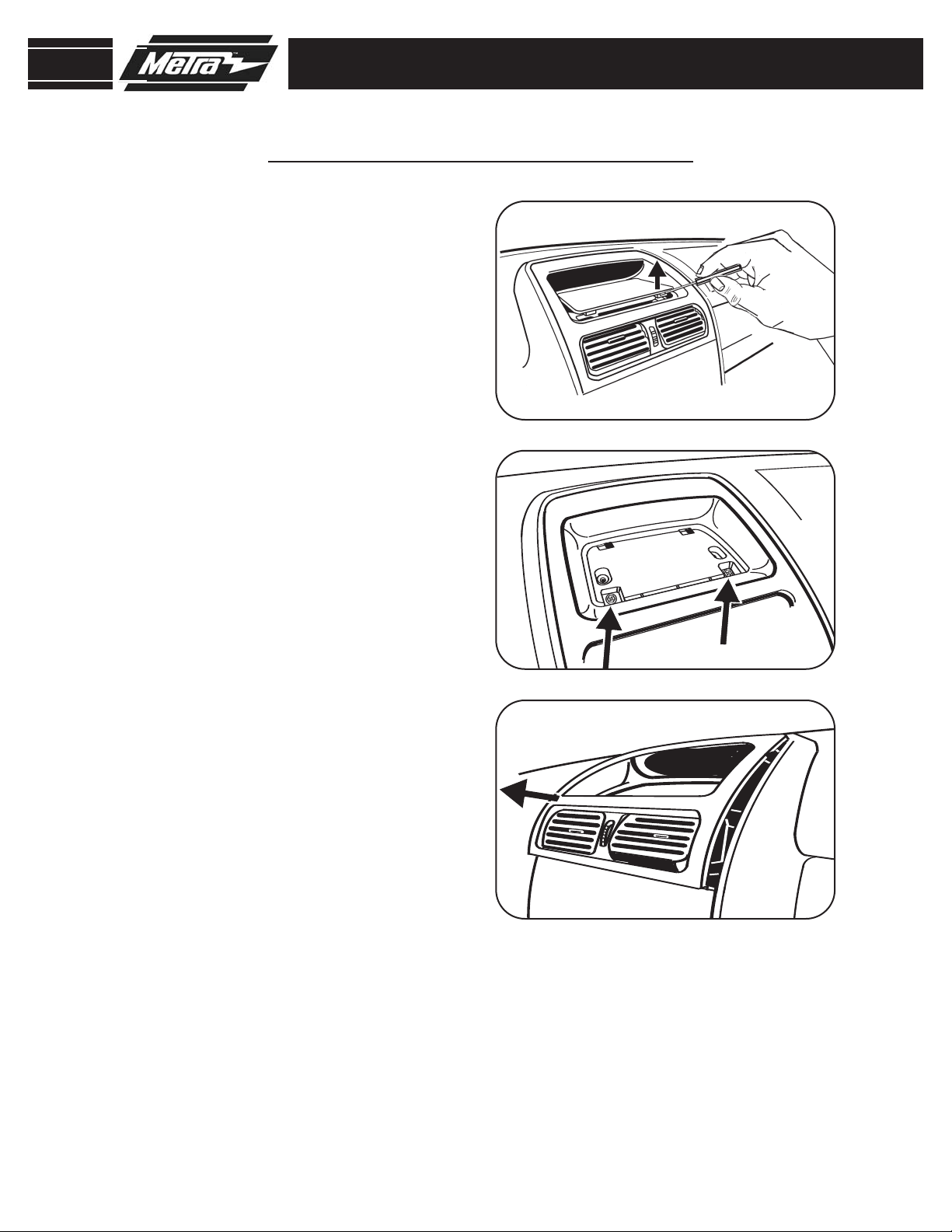
NOTE: Disconnect the negative
1
battery terminal to prevent an
accidental short circuit.
2
Using a small flat blade screwdriver,
unsnap and remove the liner from
the tray above the center vents.
(Figure A)
Remove (2) Phillips screws from
3
inside the tray.
(Figure B)
DASH DISASSEMBLY
A
B
Using a small flat blade screw driver,
4
unsnap and remove the center trim
panel including vents and tray.
(Figure C)
C
1
Page 4
99-8151
S
NOW
SNOW
T
R
AC
TRAC
OF
F
OFF
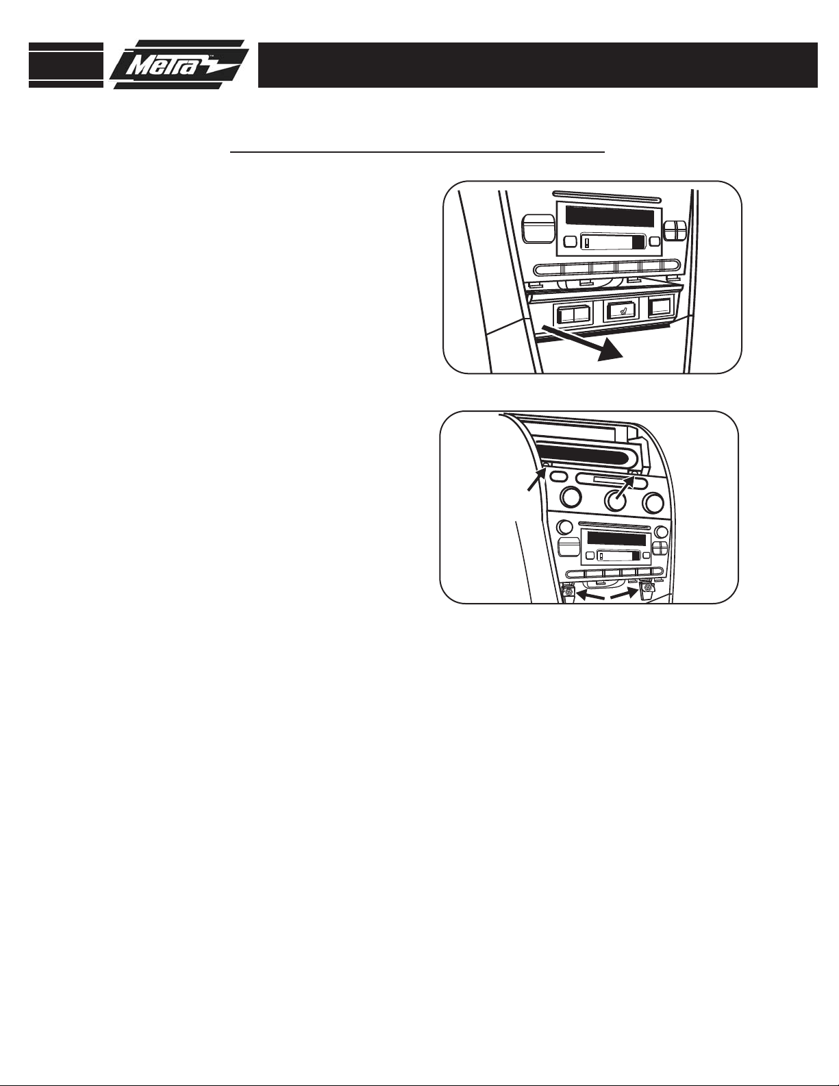
DASH DISASSEMBLY
LEXUS IS 300 2001-2005
Using a small flat blade screwdriver,
5
unsnap and remove switch panel
below radio.
Remove (4) 10mm bolts securing
6
(Figure D)
radio/climate control assembly,
unplug and remove assembly.
(Figure E)
Remove (4) Phillips screws securing
7
climate controls to the factory brackets and remove the climate controls.
D
E
2
Page 5
99-8151
LEXUS IS 300 2001-2005
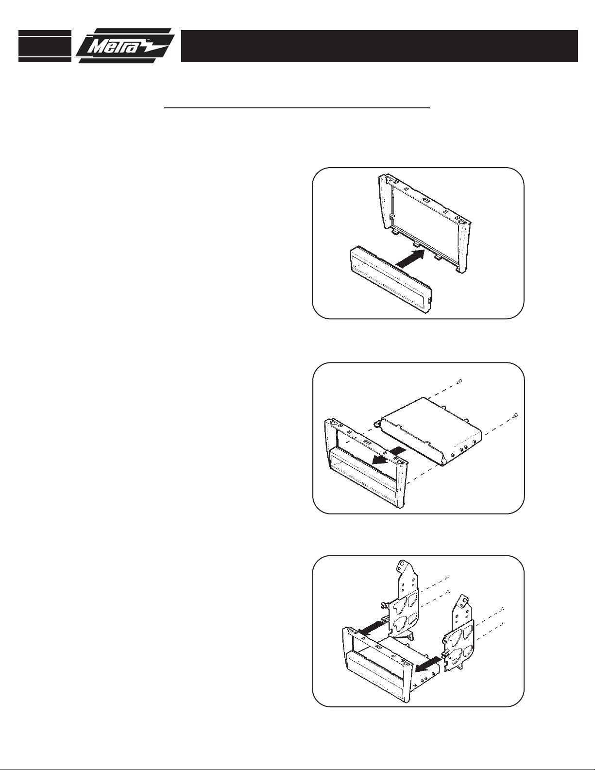
DIN RADIO PROVISION WITH POCKET
Position the pocket trim-plate in the
1
bottom of the radio housing.
(Figure A)
Attach the pocket to the pocket trim-
2
plate using (2) #8 x 3/8” Phillips
truss head screws provided with the
(Figure B)
kit.
Secure the mounting brackets to
3
radio housing/pocket assembly using
(2) #8 x 3/8” Phillips truss head
screws and (2) #8 x 3/8” Phillips pan
head screws provided with the kit.
(Figure C)
KIT ASSEMBLY
A
B
3
C
Page 6

99-8151
LEXUS IS 300 2001-2005
DIN RADIO PROVISION WITH POCKET
Mount the rear support bracket to
4
the back of the pocket using (2) #8 x
3/8” Phillips truss head screws provided with the kit.
Align and engage the (3) tabs on the
5
bottom of the climate controls to the
top edge of the radio housing/pocket
assembly. Secure the climate controls to the assembly using the (4)
factory Phillips screws previously
removed from the climate controls.
(Figure D)
KIT ASSEMBLY
D
Slide the DIN cage into the radio
6
housing/pocket assembly and secure
by bending locking tabs outward.
(Figure E)
Slide the DIN radio into the DIN cage
7
until it snaps into place.
Continue to final assembly.
8
(Figure F)
E
F
4
Page 7

99-8151
KIT ASSEMBLY
LEXUS IS 300 2001-2005
ISO RADIO PROVISION WITH POCKET
Position the pocket trim-plate in the
1
bottom of the radio housing.
(Figure A)
Attach the pocket to the pocket trim-
2
plate using (2) #8 x 3/8” Phillips
truss head screws provided with the
(Figure B)
kit.
Secure the mounting brackets to
3
radio housing/pocket assembly
using (2) #8 x 3/8” Phillips truss
head screws and (2) #8 x 3/8”
Phillips pan head screws provided
with the kit.
Mount the rear support bracket to
4
the back of the pocket using (2) #8 x
3/8” Phillips truss head screws provided with the kit.
(Figure C)
(Figure D)
A
B
C
5
D
Page 8

99-8151
KIT ASSEMBLY
LEXUS IS 300 2001-2005
ISO RADIO PROVISION WITH POCKET
Align and engage the (3) tabs on the
5
bottom of the climate controls to the
top edge of the radio housing/pocket
assembly. Secure the climate controls to the assembly using the (4)
factory Phillips screws previously
removed from the climate controls.
Mount the ISO Brackets to the radio
6
with the screws supplied with the
radio.
Slide the radio into the radio housing
7
assembly until it snaps into place.
(Figure F)
Snap the ISO Trim-plate onto the
8
Radio Housing.
(Figure E)
(Figure G)
E
F
G
Continue with final assembly.
9
Note: To remove the radio from the
housing unclip and remove the ISO
trim-plate. Using a small blade
screw driver release the clips on the
ISO snap in brackets and slide the
radio out of the housing assembly.
6
Page 9

99-8151
DOUBLE DIN RADIO PROVISION
Insert the double din spacer brackets
1
into the mounting brackets.
(Figure A)
Secure the mounting brackets/spac-
2
ers to radio housing using (2) #8 x
3/8” Phillips truss head screws and
(2) #8 x 3/8” Phillips pan head
screws provided with the kit.
(Figure B)
Align the holes in the brackets/spac-
3
ers with the holes in the aftermarket
double DIN radio and mount the
brackets/spacers to the radio using
the screws supplied with the radio.
(Figure C)
KIT ASSEMBLY
A
B
C
7
Page 10

99-8151
KIT ASSEMBLY
DOUBLE DIN RADIO PROVISION
Align and engage the (3) tabs on the
4
bottom of the climate controls to the
top edge of the radio housing
assembly. Secure the climate controls to the assembly using the (4)
factory Phillips screws previously
removed from the climate controls.
Cut and remove the center divider
5
from the double DIN trim-plate.
(Figure D)
Snap the double DIN trim-plate onto
6
the radio housing.
Continue with final assembly.
7
(Figure E)
D
E
8
Page 11

99-8151
KIT ASSEMBLY
TWO ISO UNITS PROVISION
Insert the double din spacer brack-
1
ets into the mounting brackets.
(Figure A)
Secure the mounting brackets/spac-
2
ers to radio housing using (2) #8 x
3/8” Phillips truss head screws and
(2) #8 x 3/8” Phillips pan head
screws provided with the kit.
(Figure B)
Align the holes in the brackets/spac-
3
ers with the holes in each aftermarket ISO unit and mount the brackets/spacers to the aftermarket units
using the screws supplied with the
units.
(Figure C)
A
B
C
9
Page 12

99-8151
TWO ISO UNITS PROVISION
Align and engage the (3) tabs on the
4
bottom of the climate controls to the
top edge of the radio housing
assembly. Secure the climate controls to the assembly using the (4)
factory Phillips screws previously
removed from the climate controls.
Snap the double DIN trim-plate onto
5
the radio housing.
Continue with final assembly.
6
(Figure D)
KIT ASSEMBLY
D
10
Page 13

99-8151
FINAL ASSEMBLY
FINAL ASSEMBLY
Locate the factory wiring harness in the dash and make the connection as shown.
1
Metra recomends using the proper mating adapter and making the connections as
shown. (Isolate and individually tape off the ends of any unused wires to prevent
electrical short circuit.)
Re-connect the negative battery terminal and test the unit for proper operation.
2
3
Reassemble radio and dash assemblies in reverse order of disassembly.
FINAL WIRING CONNECTIONS
Make wiring connections using the EIA color code chart shown below and the instructions included with the head
unit. Metra recommends making connections as shown below; Strip, Splice, Solder, Tape. Isolate and individually
tape off ends of any unused wires to prevent electrical short circuit.
A
B
C
D
A) Strip wire ends back 1/2"
B) Twist ends together
C) Solder
D) Tape
METRA / EIA WIRING CODE
12V Ignition / Acc . . . Red
12V Batt / Memory . . Yellow
Ground . . . . . . . . . . . Black*
Power Antenna . . . . . Blue
Amp Turn-On . . . . . . Blue / White
Amp Ground . . . . . . . Black / White
Illumination. . . . . . . . Orange
Right Front (+) . . . . . Gray
Right Front (-). . . . . . Gray / Black
Left Front (+) . . . . . . White
Left Front (-) . . . . . . . White / Black
Right Rear (+). . . . . . Violet
Right Rear (-) . . . . . . Violet / Black
Left Rear (+). . . . . . . Green
Dimmer . . . . . . . . . . Orange / White
*NOTE: When a Black wire is not present, ground radio to vehicle chassis.
All colors may not be present on all leads due to manufacturer’s specifications.
Left Rear (-) . . . . . . . Green / Black
11
Page 14

99-8151
NOTES
12
Page 15

99-8151
NOTES
13
Page 16

99-8151 INSTRUCTIONS
1-800-221-0932 www.metraonline.com
REV. 04/06/06 © COPYRIGHT 2004 METRA ELECTRONICS CORPORATION INST99-8151
 Loading...