

Page 1

INSTALLATION INSTRUCTIONS FOR PART GMLAN29-100
GMLAN29-100
*Read Important Warning On Page 1
Before Attempting Any Installation*
The GMLAN29-100 is designed to and MUST be used with the
GMOS-100i (SOLD SEPERATELY). Please refer to GMOS-100i
for 20 pin connector instructions
APPLICATIONS
BUICK
Enclave 2007-10
Lucerne 2006-10
CADILLAC
Escalade 2007-10
DTS 2006-10
SRX 2007-09
CHEVROLET
Avalanche 2007-10
Equinox 2007-09
Express 2008-10
Impala 2006-2010
Monte Carlo 2006-2007
Silverado (new body) 2007-10
Suburban 2007-09
Tahoe 2007-09
Traverse 2009
GMC
Acadia 2007-10
Savanna 2008-10
Sierra (New body) 2007-10
Yukon 2007-10
HUMMER
H2 2008-09
PONTIAC
Torrent 2007-09
Vibe 2009
SATURN
Outlook 2007-09
Vue 2008-09
SUZUKI
XL-7 2007-09
1-800-221-0932 axxessinterface.com
© COPYRIGHT 2004-2010 METRA ELECTRONICS CORPORATION
Page 2
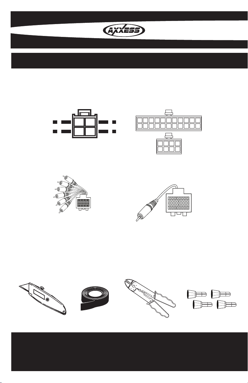
INTERFACE COMPONENTS
IGNITION
TERMINALS
WIRE
CUTTER
M3.5
M2.6
M3
M5
M4
ISO
6
2.5
1.5
4 pin
•A) 4 pin harness with stripped leads •B) 22 pin to 30 pin GM harness •C) 16 pin backup camera harness
•D) 16 pin RSE harness
A
C
B
D
TOOLS REQUIRED FOR INSTALLATION
•Cutting Tool •Tape •Crimping Tool •Connectors (I.E. butt-connectors, bell caps, ECT…)
Page 3

KNOWLEDGE IS POWER
Enhance your installation and fabrication skills by
enrolling in the most recognized and respected
mobile electronics school in our industry.
Log onto www.installerinstitute.com or call
800-354-6782 for more information and take steps
toward a better tomorrow.
TABLE OF CONTENTS
Installing The Interface .............................................................. 1
Installing The GMLAN29-100 ................................................. 1
Programming SWC ..................................................................... 2
Testing The GMLAN29-100 ...................................................... 2
Metra recommends MECP certified
technicians
Page 4

*Important: Before beginning any of the following,
disconnect the negative battery terminal to prevent an
accidental short circuit.
INSTALLING THE INTERFACE
From the 22 way harness:
Connect the Black wire with the ring terminal to the back of the aftermarket radios chasis•
Connect the 3.5mm jack to your aftermarket radios steering wheel control input (if •
equipped)
From the 30 way harness:
Connect the Black wire to the ground wire of the aftermarket radio•
Connect the RCA’s on the 8 pin harness to the AUX in on the aftermarket radio (if •
equipped)
Connect the Yellow wire to the constant wire of the aftermarket radio.•
The GMLAN29-100 comes set up for amplied systems. If the vehicle is not amplied
disconnect the 4 pin harness located between the 30 way and 22 way connector. Connect
the supplied 4 pin speaker harness and connect the following:
Connect the Violet wire to the right rear positive wire of the aftermarket radio•
Connect the Violet/Black wire to the right rear negative wire of the aftermarket radio•
Connect the Green wire to the left rear positive wire of the aftermarket radio•
Connect the Green/Black wire to the left rear negative wire of the aftermarket radio•
INSTALLING THE GMLAN29-100
With all the connections completed, plug the 20, 22, and 8 pin harnesses into the GMOS-100i
(sold separately).
Reconnect the negative battery terminal.•
Plug the 30 pin GM harness into the vehicle side harness, and plug the aftermarket radio •
harness into the aftermarket radio.
Cycle the key by turning the ignition on then back off, then back on again to test the radio. •
1
Page 5

PROGRAMMING SWC
Turn on the ignition•
The LED will begin to blink rapidly•
Turn on the aftermarket radio•
Press volume up until radio responses•
TESTING THE GMLAN29-100
Turn the ignition on, and then turn the aftermarket radio on. •
Push the Onstar button, the radio should turn off (radio will mute if mute wire is •
connected) and you should hear Onstar. Push the Onstar cancel button and the radio
should come back on.
2
Page 6

NOTES
Page 7

NOTES
Page 8

INSTALLATION INSTRUCTIONS FOR PART GMLAN29-100
REV. 4/2/2010
1-800-221-0932 axxessinterface.com
© COPYRIGHT 2004-2010 METRA ELECTRONICS CORPORATION
 Loading...