

Page 1
INSTALLATION INSTRUCTIONS FOR PART GMLAN11-100
GMLAN11-100
*Read Important Warning On Page 1
Before Attempting Any Installation*
The GMLAN11-100 is designed to and MUST be used with the
GMOS-100i (SOLD SEPERATELY). Please refer to GMOS-100i
for 20 pin connector instructions.
APPLICATIONS
CHEVROLET
Cobalt 2007-10
HHR 2006-10
Malibu 2008-10
PONTIAC
G5 2007-08
G6 2009
Solstice 2006-09
SATURN
Aura 2006-09
Sky 2006-09
1-800-221-0932 axxessinterface.com
© COPYRIGHT 2004-2010 METRA ELECTRONICS CORPORATION
Page 2
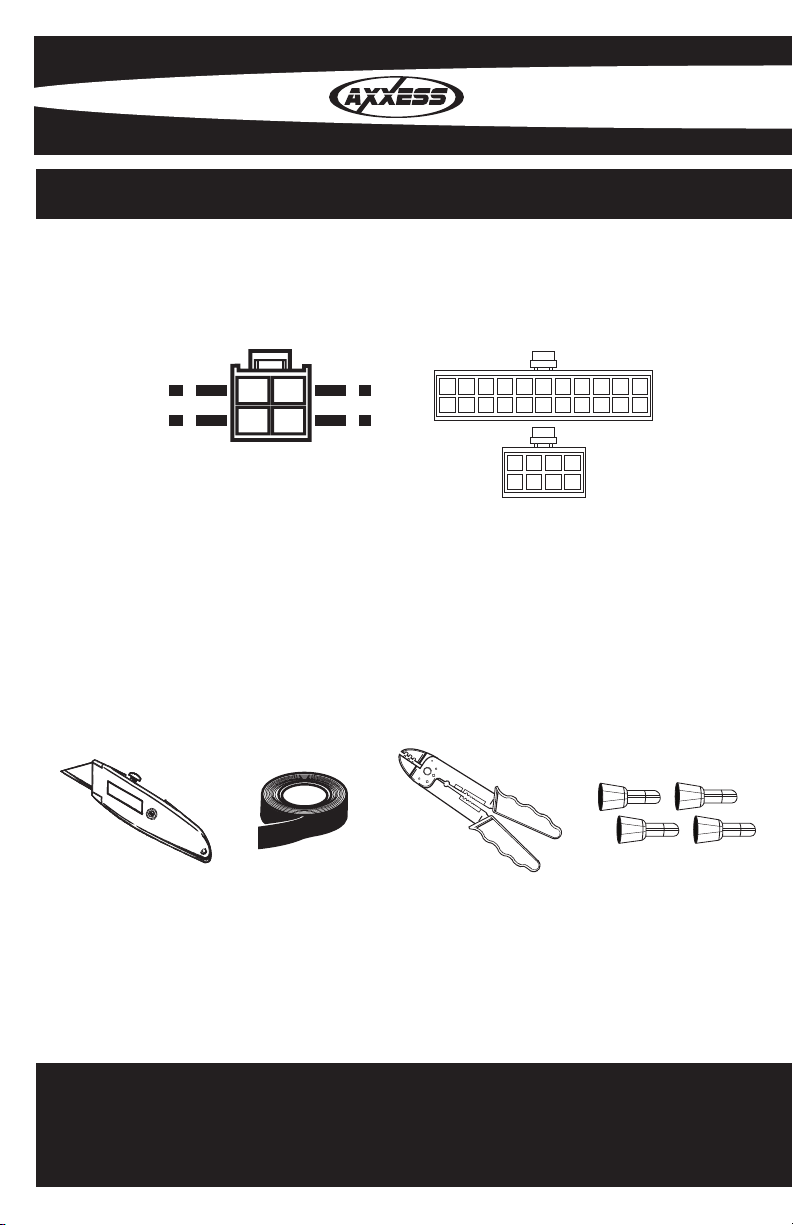
INTERFACE COMPONENTS
IGNITION
TERMINALS
WIRE
CUTTER
M3.5
M2.6
M3
M5
M4
ISO
6
2.5
1.5
4 pin
•A) 4 pin harness with stripped leads •B) 22 pin to 30 pin GMLAN car side harness
A B
TOOLS REQUIRED FOR INSTALLATION
•Cutting Tool •Tape •Crimping Tool •Connectors (I.E. butt-connectors, bell caps, ECT…)
Page 3

KNOWLEDGE IS POWER
Enhance your installation and fabrication skills by
enrolling in the most recognized and respected
mobile electronics school in our industry.
Log onto www.installerinstitute.com or call
800-354-6782 for more information and take steps
toward a better tomorrow.
TABLE OF CONTENTS
Installing The Interface .............................................................. 1
Installing The GMLAN11-100 ................................................. 1
Programming SWC ..................................................................... 2
Testing The GMLAN11-100 ...................................................... 2
Metra recommends MECP certified
technicians
Page 4

*Important: Before beginning any of the following,
disconnect the negative battery terminal to prevent an
accidental short circuit.
INSTALLING THE INTERFACE
From the 22 way harness:
Connect the Black wire with the ring terminal to the back of the aftermarket radios chasis•
Connect the 3.5mm jack to your aftermarket radios steering wheel control input (if •
equipped)
From the 30 way harness:
Connect the Black wire to the ground wire of the aftermarket radio•
Connect the RCA’s on 8 pin harness to the AUX in on the aftermarket radio (if equipped) •
The XIA-LCD is need to view Satellite stations (sold separately)
Connect the Yellow wire to the constant wire of the aftermarket radio.•
The GMLAN11-100 comes set up for amplied systems. If the vehicle is not amplied
disconnect the 4 pin harness located between the 30 way and 22 way connector.
Connect the supplied 4 pin speaker harness and connect the following:
Connect the Violet wire to the right rear positive wire of the aftermarket radio•
Connect the Violet/Black wire to the right rear negative wire of the aftermarket radio•
Connect the Green wire to the left rear positive wire of the aftermarket radio•
Connect the Green/Black wire to the left rear negative wire of the aftermarket radio•
INSTALLING THE GMLAN11-100
With all the connections completed, plug the 20, 22, and 8 pin harnesses into the GMOS-•
100i (sold separately).
1
Page 5

Reconnect the negative battery terminal.•
Plug the 30 pin GM harness into the vehicle side harness, and plug the aftermarket radio •
harness into the aftermarket radio.
Cycle the key by turning the ignition on then back off, then back on again to test the radio. •
PROGRAMMING SWC
Turn on the ignition•
The LED will begin to blink rapidly•
The following buttons must be pressed in the following order:
Volume up, Seek up, Band, PTT/Mute, Fan up (Each button press will be acknowledged with
the LED on steadily)
If any of the above buttons are not present , substitute with Volume up. For example, if a
vehicle does not Band and Fan up, you would press Volume up, Seek up, Volume up, PTT/
MUTE, Volume up.
After you have pressed ve buttons, the LED will turn off, then blink a number of times
according to the detected vehicle type. If SWC does not recognize, please note the number of
blinks and contact tech support.
If you press the buttons incorrectly, turn off the ignition and repeat the above steps. If you do
it wrong, it can be done again by pressing the volume up button for 15 seconds until the LED
goes into fast blink mode again.
TESTING THE GMLAN11-100
Turn the ignition on, and then turn the aftermarket radio on. •
Push the Onstar button, the radio should turn off (radio will mute if mute wire is •
connected) and you should hear Onstar.
Push the Onstar cancel button and the radio should come back on.•
2
Page 6

NOTES
Page 7

NOTES
Page 8

INSTALLATION INSTRUCTIONS FOR PART GMLAN11-100
REV. 4/2/2010
1-800-221-0932 axxessinterface.com
© COPYRIGHT 2004-2010 METRA ELECTRONICS CORPORATION
 Loading...