

Page 1

POWER MANAGER 2000
Rack Mount Home Theater Power Center
User Guide
Model ESP-602R
© Copyright 2011 Metra Electronics
The informa on contained herein is subject to change without no ce.
This document contains proprietary informa on protected by copyright law.
No part of this document may be photocopied or reproduced without prior
wri en consent.
Page 2

TABLE OF CONTENTS INTRODUCTION
Thank you for purchasing the Power Manager 2000. Your new rack mountable
home theater power manager provides clean AC power to sensi ve home theater
electrical equipment. Six always on plus six switched outlets (twelve total) provide
premium audio and video output with surge protec on and noise fi ltering. Addi onal
connec ons supply Ethernet and telephone/data line condi oning protec on along
with three pairs of DSS/coaxial connec ons for cable protec on.
Features
• Four kinds of fi lter circuitry isolates and protects audio, video, digital and high
current equipment.
• LCD display shows voltage and amperage levels.
• System provides overload protec on with a 120V/15A electrical ra ng.
• Remote 110V and 12V DC trigger allows remote turn on/off of switched outlets.
• Telephone/data line, Ethernet (network) and DSS/coax surge protec on provided.
• A total of twelve outlets includes 6 switched and 6 always on.
• Rack mountable system features sturdy metal housing.
Safety Information
• To reduce the risk of electrical shock, unplug the Power Manager and allow it to
cool before cleaning.
• There are no replaceable parts in the Power Manager 2000. Do not a empt to
disassemble this unit for any reason.
• Use in an indoor, dry loca on only.
POWER MANAGER 2000 Page 2Page 1 POWER MANAGER 2000
IntroducƟ on .................................................................................................... 2
Features ..............................................................................................................2
Safety Informa on .............................................................................................. 2
Package Contents ............................................................................................ 3
InstallaƟ on ......................................................................................................3
DescripƟ ons ....................................................................................................4
ConnecƟ ons ....................................................................................................5
OperaƟ on ........................................................................................................ 6
Remote Trigger Opera on................................................................................... 6
Remote AC Opera on ........................................................................................6
LCD Control Panel ...............................................................................................7
LED Indicators .....................................................................................................7
Specifi caƟ ons ..................................................................................................8
Physical ...............................................................................................................8
Electrical .............................................................................................................. 8
Page 3
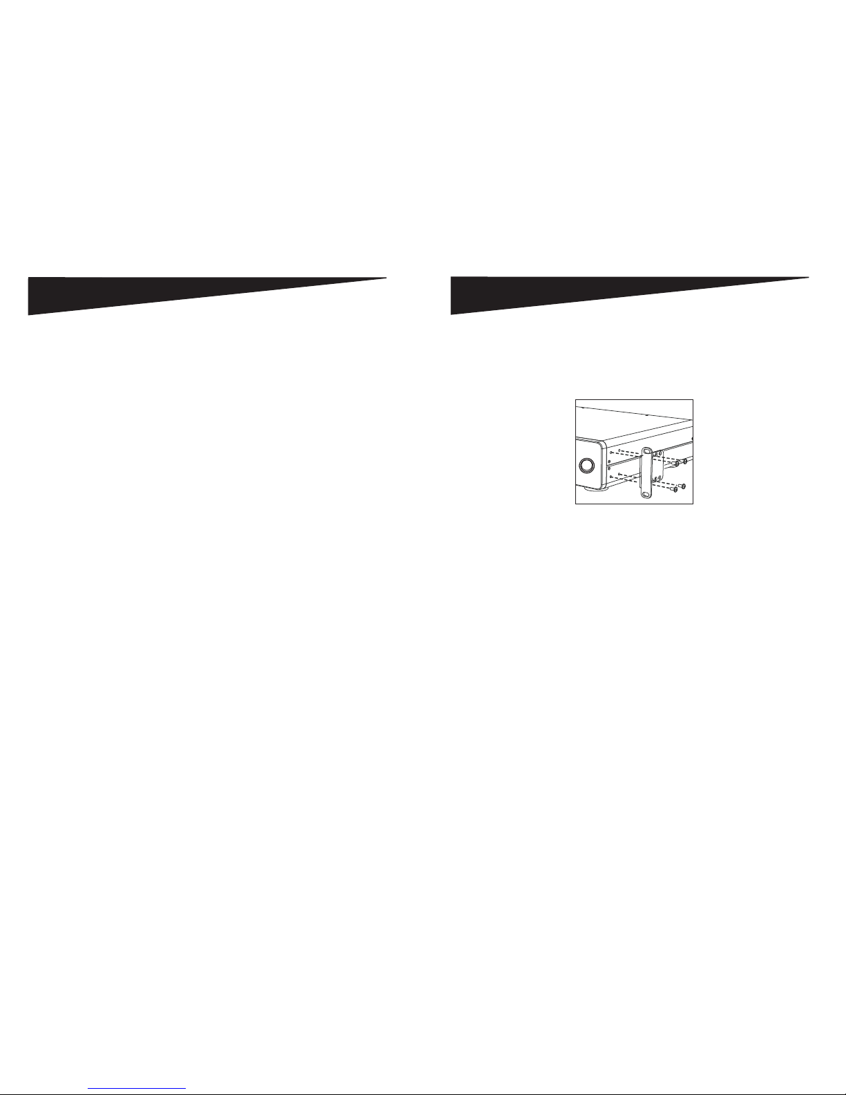
INSTALLATION
The Power Manager 2000 can be mounted to a standard AV equipment rack or to
an equipment rack installed inside a cabinet. Refer to Figure 1 when a aching the
moun ng brackets to the Power Manager.
NOTE: Moun ng bracets sold separately.
Figure 1 - OpƟ onal Rack InstallaƟ on
Page 3 POWER MANAGER 2000 POWER MANAGER 2000 Page 4
• Home Theater Power Manager
• This User Manual
PACKAGE CONTENTS
Page 4
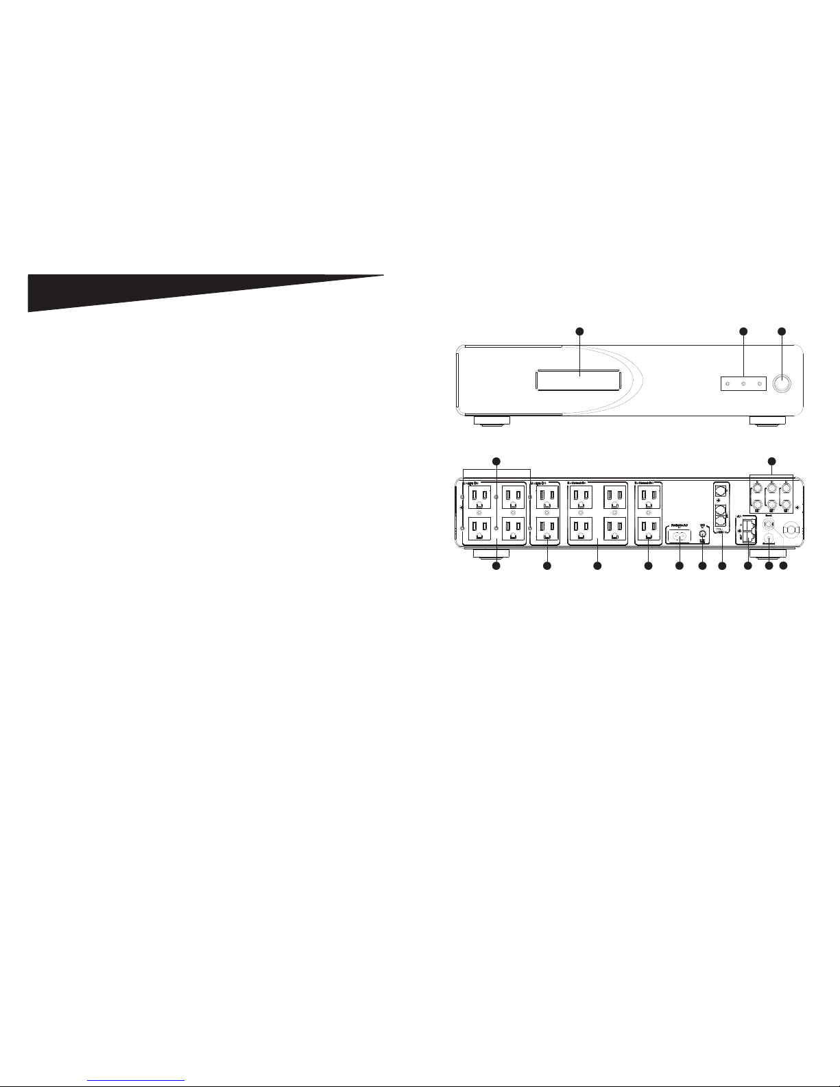
DESCRIPTIONS
1. On/Off Power Push Bu on – Turn power to the switched outlets on/off .
2. LCD Display – Monitor the Power Manager’s main func ons.
3. LED Power Indicators – Monitor ground, protec on and switched power statuses.
4. Bank 1 Digital Filter – Connect digital components to reduce line noise and
interference.
5. Bank 2 Digital Filter – Connect digital components to reduce line noise and
interference.
6. Bank 3 Video Filter – Connect video components to reduce line noise and
interference.
7. Bank 4 Audio Filter – Connect audio components to reduce line noise and
interference.
8. Always On Indicator – Use the green indicators to determine when the switched
outlets are turned “on.”
9. Remote AC IN – Connect a remote AC control cable to turn your Power Manager
on/off through a preamplifi er or receiver equipped with a switched AC power
outlet.
10. DC IN – Control the Power Manager using the remote trigger func on of another
power management unit.
11. Telephone Line Input/Output – Protect your internal modem, TEL/FAX, or DSL
lines from power surges and spikes.
12. DSS/Coax Line Input/Output – Protect coaxial cable lines from power surges and
spikes that can disturb and damage your equipment.
13. Ethernet Network Input/Output – Protect your Ethernet network line access from
power surges and spikes.
14. Ground – Use as a common grounding point for ungrounded devices.
15. 15-Amp Overload Resetable Circuit Breaker – The circuit breaker provides
overload protec on with a manually recoverable func on.
1
32
Figure 2 - Front View Controls and Indicators
8
4567
9
12
10
13
11
14
15
Figure 3 - Rear View Controls
POWER MANAGER 2000 Page 6Page 5 POWER MANAGER 2000
Page 5
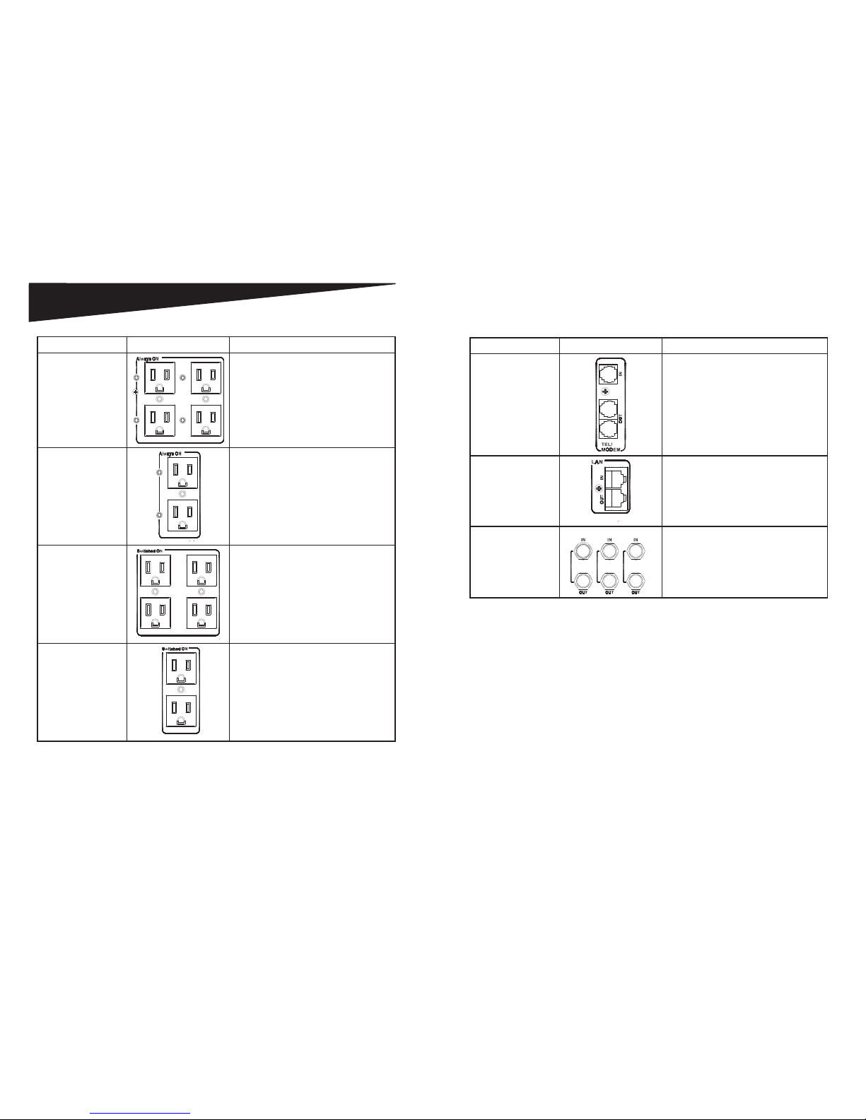
CONNECTIONS
Category Figure Recommended ConnecƟ ons
Bank 1
(Digital Filter)
DVD
DVR
HDTV
Cable
Satellite
Bank 2
(Digital Filter)
DVD
DVR
HDTV
Cable
Satellite
Bank 3
(Video Filter)
VCR
TV
Monitor
Bank 4
(Audio Filter)
Tape Deck
CD Player
Receiver
Auxiliary
Category Figure Recommended ConnecƟ ons
Telephone/
Data Line
Connect your modem,
telephone line or fax lines to these
standard RJ11 phone jacks. The
Power Manager includes one IN port
and two OUT ports.
LAN (Local Area
Network) Line
Connect local area network cables to
these standard RJ45 Ethernet jacks.
DSS/Coaxial Cable
Lines
Connect your cable TV, satellite TV,
antenna, HDTV, broadband or other
coaxial cable lines.
POWER MANAGER 2000 Page 8
Page 7 POWER MANAGER 2000
Page 6
POWER MANAGER 2000 Page 10Page 9 POWER MANAGER 2000
OPERATION
Remote Trigger Operation
This power manager can be controlled remotely by another power manager equipped
with a remote trigger out feature. To use remote trigger control, connect a remote
DC cable from the “DC OUT” connec on on the power manager equipped with
remote trigger out to the “DC IN” connec on (Figure 4) on the Power Manager 2000.
Figure 4 - DC IN ConnecƟ on
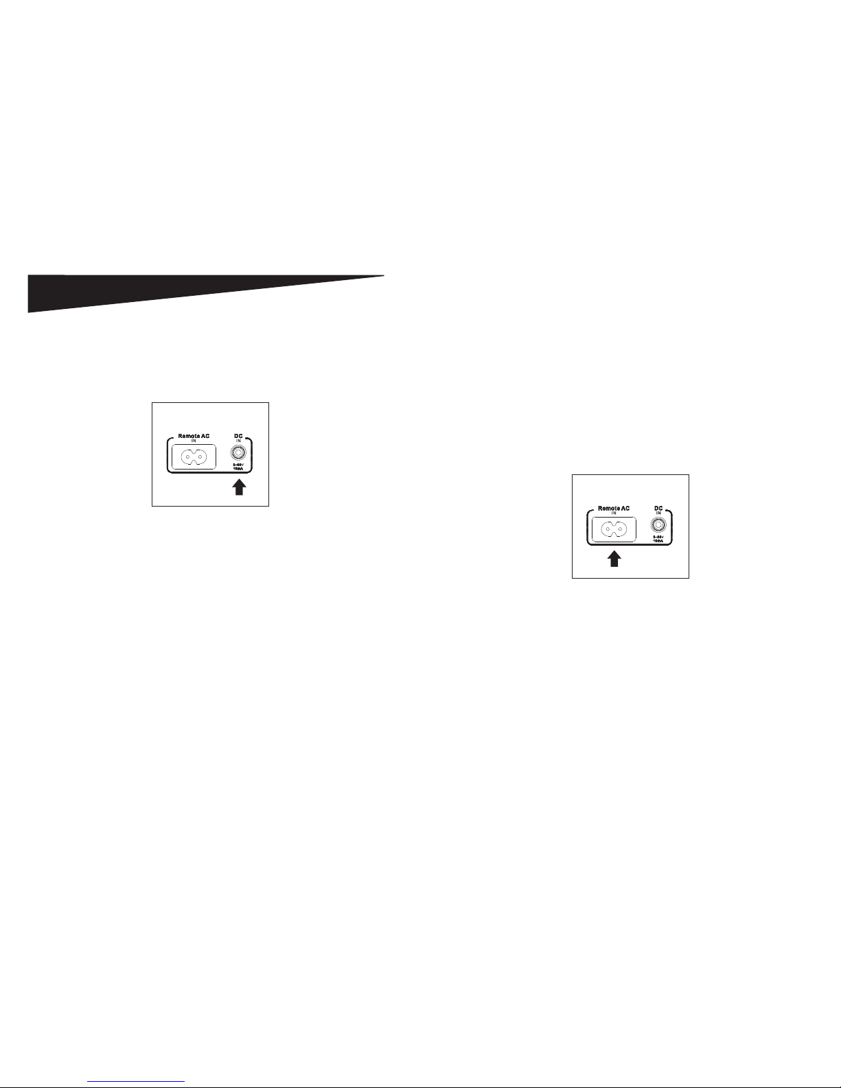
Remote AC Operation
The Remote AC func on enables you to turn your Power Manager on or off using a
preamplifi er or receiver equipped with a switched AC power outlet.
NOTE: You cannot use the POWER bu on on the front of the unit to turn the Power
Manager on/off while an exis ng external power signal is supplied to either the AC or
DC remote input connector.
To install a remote AC control cable:
1. Plug the female end of the remote AC control cable into the “Remote AC IN”
outlet (Figure 5) located on the back of the Power Manager.
Figure 5 - Remote AC IN ConnecƟ on
2. Turn the Power Manager off .
3. Plug the 2-pronged male end of the remote AC control cable into a switched
power outlet on a preamplifi er or receiver. When the receiver or preamplifi er
is turned on, the switched outlets on the Power Manager 2000 will turn on
automa cally.
Page 7

OPERATION
LCD Panel
The Power Manager 2000 is equipped with an LCD panel (Figure 6) that allows the
user to monitor input voltage and output current.
20
5.0
VOLTS CURRENT
Figure 6 - LCD Panel
• “VOLT” indicates the input voltage from the AC wall outlet.
• “AMPS” indicates the output current from the outlet banks.
LED Indicators
The LED indicators on the front panel (Figure 7) allow you to monitor important
power and safety informa on.
GROUNDED
PROTECTED SWITCHED
POWER
Figure 7 - Front Panel LED Indicators
• “GROUNDED” indicates the status of the AC outlet. Green indicates that the AC
wall outlet is properly grounded.
• “PROTECTED” indicates the status of the Power Manager surge protec on. Yellow
indicates that the surge protec on is turned on.
• “SWITCHED POWER” indicates whether the “Switched” outlets are ON or OFF.
Page 11 POWER MANAGER 2000 POWER MANAGER 2000 Page 12
Page 8

SPECIFICATIONS
Physical
Width 487mm
Height 88.9mm
Length 352.9mm
Weight 6.7kgs
Power Cord 14 AWG with 45 degree angle (8 )
Electrical
Electrical Ra ng 120V/15A
Clamping Voltage L-N 330V, L-G 500V, N-G 500V
Surge Energy Joule Ra ng 6495J
Maximum Peak Spike Current 432000A
Maximum Spike Voltage 6KV
EMI/RFI Noise Filter
SURGE
X2 Capacitor (uF) 0.22uF*2
Coil (T) 8uH*2
Frequency (KHz) 150KHz~100MHz
A enua on (dB) up to 45dB
EMI/RFI Noise Filter
DIGITAL OUTLETS
(Banks 1 & 2)
X2 Capacitor (uF) 1uF*3
Coil (T) 850uH*2
Frequency (KHz) 150KHz~100MHz
A enua on (dB) up to 65dB
EMI/RFI Noise Filter
VIDEO OUTLETS
(Bank 3)
AUDIO OUTLETS
(Banks 4)
X2 Capacitor (uF) 1uF*3
Coil (T) 1.4mH*2
Frequency (KHz) 150KHz~100MHz
A enua on (dB) up to 70dB
Electrical (continued)
DC Trigger Input Jack ψ 3.5
Voltage 3~30V
Current Requirement 10mA
LAN Circuit Connectors RJ45
Wires Protected 1, 2, 3, 6
Communica on Speed 10 Base
Tel/Fax/Modem Energy (Joules) 160J
Let Through Voltage (V) <40V
DSS/COAX Cable
Protec on
Surge Arrestor Gas Tube
Breakdown Voltage 75V
Inser on Loss @10MHz <0.1dB
Connectors 3 Pairs, Gold Plated
NOTE: Specifi ca ons subject to change without no ce.
POWER MANAGER 2000 Page 14
Page 13 POWER MANAGER 2000
 Loading...