

Page 1
INST 7500
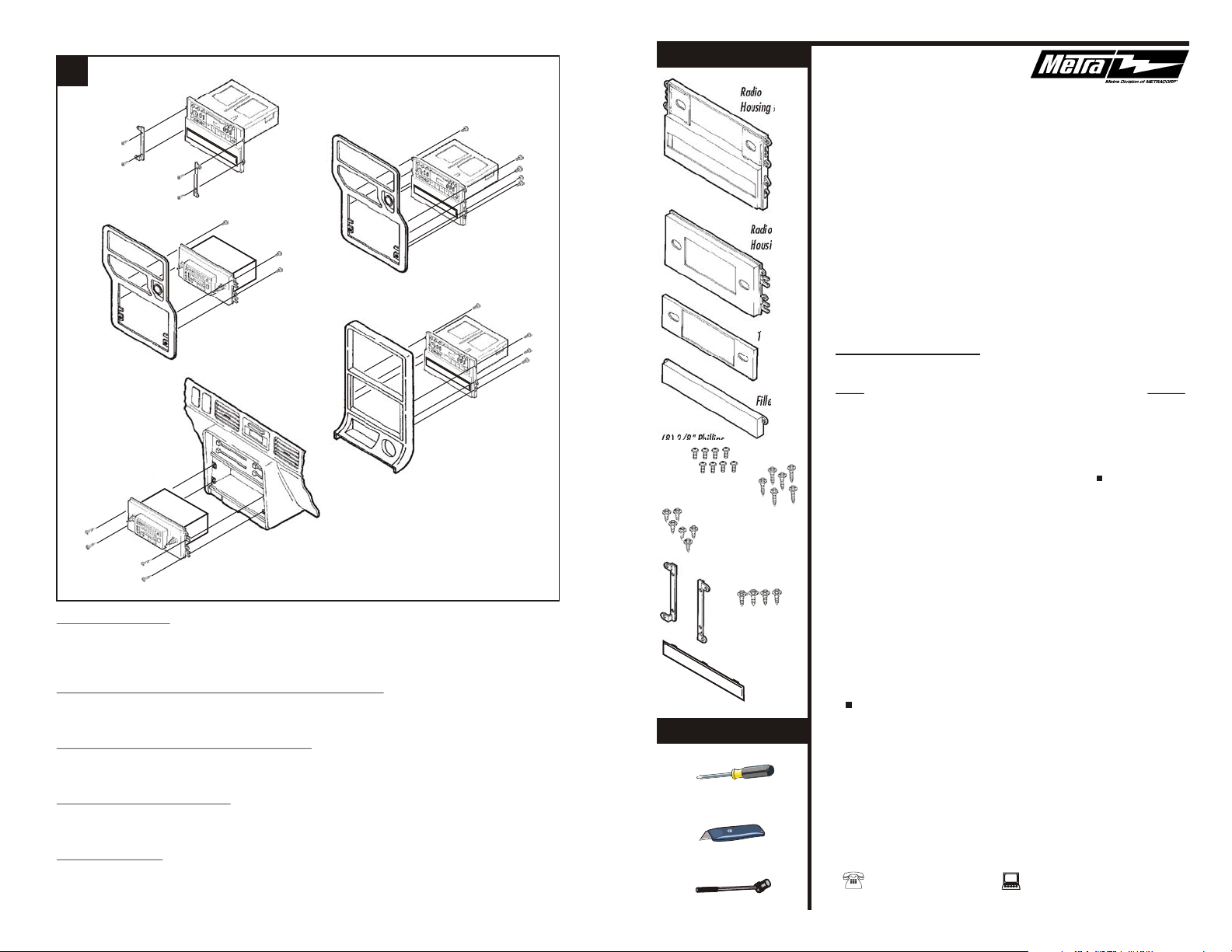
KIT COMPONENTS
6
Fig. A
Fig. C
Radio
Housing #1
99-7500
DW-7501
Fig. B
Fig. E
Fig. D
B-SERIES PICKUP: Re-connect the battery terminal and test the unit for proper operation.
Mount Bracket Set #1 to the Housing with (4) ½" Hex-head Screws supplied. Mount the
head unit/kit assembly to the back of the dash trim bezel with (4) screws removed in step #1
and re-attach the bezel. (see Fig. A)
323 1986-89, 626 / MX6 (models using Radio Housing #2): Re-connect the battery terminal
and test the unit for proper operation. Mount the head unit/kit assembly to the back of the dash
trim bezel with (4) 3/8" Phillips Screws supplied and re-attach the bezel. (see Fig. B)
626 / MX6 (models using Radio Housing #1: Re-connect the battery terminal and test the
unit for proper operation. Mount the head unit/kit assembly to the back of the dash trim bezel
with (8) 3/8" Phillips Screws supplied and re-attach the bezel. (see Fig. C)
323 1990-94, MPV, PROTEGE: Re-connect the battery terminal and test the unit for proper
operation. Mount the head unit/kit assembly to the sub-dash with (4) ¾" Hex-head Screws
supplied. (see Fig. D)
Radio
Housing #2
Trimplate
Filler Bar
(8) 3/8" Phillips
Screws
(6) ¾" Hex-head Screws
(6) 3/8" Hex-head Screws
(4) ½" Hex-head
Screws
Bracket Set #1
Equalizer
Dummy
Plate
TOOLS REQUIRED
Phillips screwdriver
INSTALLATION
INSTRUCTIONS
APPLICATIONS
CAR PAGE
MAZDA
323 1986-89*...............................................................................1
323 1990-94*...............................................................................1
626 (models w/factory receiver/tape deck/eq/pocket) 1986-92....2
626 (models w/factory receiver/pocket) 1986-92* ......................2
929 1988-91.................................................................................3
B-Series Pickup 1986-93................................................................3
Miata 1990-99..............................................................................4
MPV 1989-95*.............................................................................. 4
MX6 (models w/factory receiver/tape deck/eq/pocket) 1986-92...2
MX6 (models w/factory receiver/pocket) 1986-92*....................... 2
Protege 1990-94*......................................................................... 1
RX-7 1986-91............................................................................... 5
* For aftermarket DIN head unit installations, order Metra's 99-7501
For models with pockets 3¾" or taller, order Metra's 99-7501
929, MIATA, RX-7: Re-connect the battery terminal and test the unit for proper operation.
Mount the head unit/kit assembly to the back of the dash trim bezel with (6) 3/8" Hex-head
Screws supplied and re-attach the bezel. (see Fig. E)
7
rev. 300801
Cutting tool
Socket wrench
1-800-221-0932 www.metraonline.com
© COPYRIGHT 2001 METRA ELECTRONICS CORPORATION
Page 2
MAZDA 323 1986-89
1
2
3b
Fig. A
Disconnect the negative battery terminal to
prevent an accidental short circuit. Remove
the ashtray and (2) screws exposed in the
ashtray cavity. Unclip the radio trim bezel
and disconnect the wiring. Remove (4)
screws securing the factory dummy plate to
the back of the bezel and discard the plate.
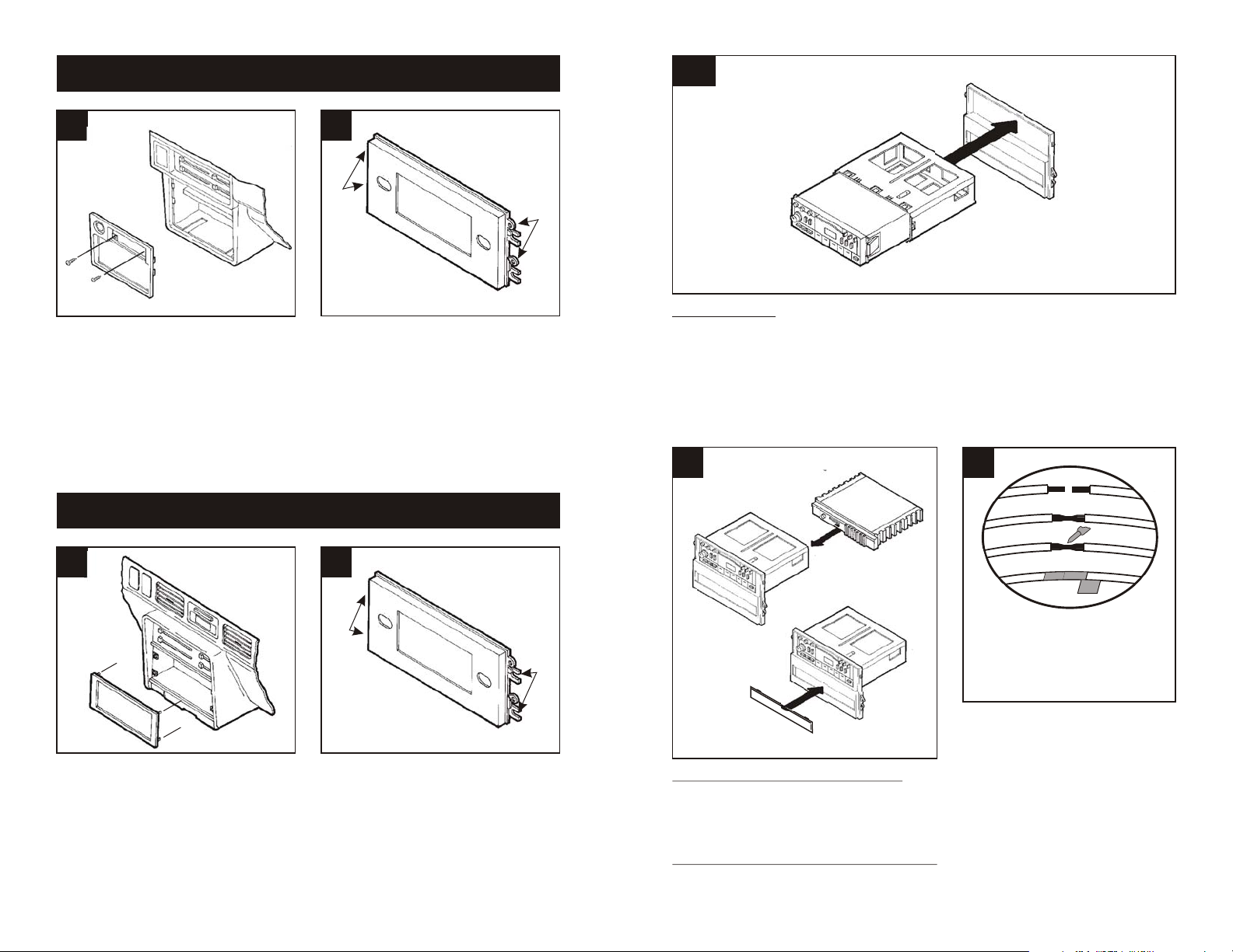
MAZDA 323 / Protege 1990-94
1
"E"
Cut and remove all mounting tabs on Radio
Housing #2 EXCEPT tabs "E". The
mounting tabs can be identified by the
stamped letter on the back of each tab. Skip
to the Installation Instructions for ALL
VEHICLES on Page #5.
"E"
2
"D"
"D"
DIN HEAD UNITS: For models using Radio Housing #1, cut and remove the shaft supports.
Slide the DIN cage into the Housing and secure by bending the metal locking tabs down. Slide
the aftermarket head unit into the cage until secure. (see Fig. A)
4
Fig. A
5
A
B
C
D
A) Strip wire ends back ½"
B) Twist ends together
C) Solder
D) Tape
Disconnect the negative battery terminal to
prevent an accidental short circuit. Gently
pry out on the radio trim bezel and remove.
Remove (4) screws securing the factory
head unit and disconnect the wiring.
1
Cut and remove all mounting tabs on Radio
Housing #2 EXCEPT tabs "D". The
mounting tabs can be identified by the
stamped letter on the back of each tab. Skip
to the Installation Instruc-tions for ALL
VEHICLES on Page #5.
Fig. B
IF AN EQUALIZER WILL BE INCLUDED: Slide
the aftermarket equalizer into the back of the
Radio Housing. Using the hardware included
with the equalizer, mount the unit to the kit. (see
Fig. A)
IF AN EQUALIZER WILL NOT BE INCLUDED:
Snap the Equalizer Dummy Plate into the Radio
Housing. (see Fig. B)
Locate the factory wiring harness in the
dash. Metra recommends using the
proper mating adaptor and making
connections as shown. (Isolate and
individually tape off the ends of any
unused wires to prevent electrical short
circuit).
6
Page 3

MAZDA RX-7 1986-91
MAZDA 626 / MX6 1986-92
(models equipped with factory receiver/pocket)
1
2
"A"
"A"
"A"
"A"
"A"
"A"
1
2
"E"
"E"
Disconnect the negative battery terminal to
prevent an accidental short circuit. Remove
the ashtray and (2) screws exposed in the
ashtray cavity. Unsnap the gear shifter trim
and remove (2) screws exposed. Unsnap
the climate control trim bezel and remove (2)
screws exposed. Remove the dash trim
bezel and disconnect the wiring. Remove
(4) screws securing the factory head unit
and disconnect the wiring.
Cut and remove all mounting tabs on Radio
Housing #1 EXCEPT tabs "A". The
mounting tabs can be identified by the
stamped letter on the back of each tab. Skip
to the Installation Instructions for ALL
VEHICLES on Page #5.
ALL VEHICLES
3a
Fig. A
Fig. B
2-SHAFT HEAD UNITS: For models using Radio Housing #1, attach the Faceplate to the
Housing. Slide the aftermarket head unit into the kit and secure with shaft nuts. (see Fig. A).
For models using Radio Housing #2, slide the aftermarket head unit into the kit and secure
with shaft nuts. (see Fig. B)
5
Disconnect the negative battery terminal to
prevent an accidental short circuit. Remove
the ashtray and (2) screws exposed.
Remove the pocket and (2) screws exposed.
Remove the radio trim bezel and disconnect
the wiring. Remove (4) screws securing the
factory dummy plate to the back of the bezel
and discard the plate.
Cut and remove all mounting tabs on Radio
Housing #2 EXCEPT tabs "E". The
mounting tabs can be identified by the
stamped letter on the back of each tab. Skip
to the Installation Instructions for ALL
VEHICLES on Page #5.
MAZDA 626 / MX6 1986-92
(models equipped with factory receiver/tape deck/eq/pocket)
1
Disconnect the negative battery terminal to
prevent an accidental short circuit. Remove
the ashtray and (2) screws exposed.
Remove the pocket and (2) screws exposed.
Remove the radio trim bezel and disconnect
the wiring. Remove (4) screws securing the
factory dummy plate to the back of the bezel
and discard the plate.
"B"
2
"B"
"B"
"B"
Cut and remove all mounting tabs on Radio
Housing #1 EXCEPT tabs "B". The
mounting tabs can be identified by the
stamped letter on the back of each tab. Skip
to the Installation Instructions for ALL
VEHICLES on Page #5.
"B"
"B"
"B"
"B"
2
Page 4

MAZDA 929 1988-91
MAZDA Miata 1990-99
1
Disconnect the negative battery terminal to
prevent an accidental short circuit. Reach
behind the console and remove (2) nuts
supporting the head unit carrier. Remove
the factory head unit and disconnect the
wiring..
MAZDA B-Series Pickup 1986-93
1
2
"A"
"A"
"A"
"A"
"A"
"A"
Cut and remove all mounting tabs on Radio
Housing #1 EXCEPT tabs "A". The
mounting tabs can be identified by the
stamped letter on the back of each tab. Skip
to the Installation Instructions for ALL
VEHICLES on Page #5.
2
"C"
1
Disconnect the negative battery terminal to
prevent an accidental short circuit. Remove
(2) screws from the center console storage
compartment. Remove (1) screw under the
ashtray. Remove (1) screw from each side
of the center console panel and remove the
panel. Remove (1) screw exposed at the
base of the dash trim bezel. Pop out the a/c
vents and remove (2) screws exposed.
Remove the dash trim bezel.
MAZDA MPV 1989-95
2
"A"
"A"
"A"
"A"
"A"
"A"
Cut and remove all mounting tabs on Radio
Housing #1 EXCEPT tabs "A". The
mounting tabs can be identified by the
stamped letter on the back of each tab. Skip
to the Installation Instructions for ALL
VEHICLES on Page #5.
Disconnect the negative battery terminal to
prevent an accidental short circuit. Remove
(2) screws from each side of the radio trim
bezel. Remove the ashtray and (1) screw
from the rear support tab. Remove the radio
trim bezel/sub-bracket assembly. Remove
(4) screws securing the sub-bracket to the
back of the radio trim bezel. Loosen (2)
screws on top of the bezel and remove the
sub-bracket from the bezel.
3
"C"
Cut and remove all mounting tabs on Radio
Housing #1 EXCEPT tabs "C". The
mounting tabs can be identified by the
stamped letter on the back of each tab. Skip
to the Installation Instructions for ALL
VEHICLES on Page #5.
1
Disconnect the negative battery terminal to
prevent an accidental short circuit. Remove
the ashtray and (2) screws exposed in the
ashtray cavity. Remove the radio trim bezel
and disconnect the wiring. Remove (4)
screws securing the factory head unit and
disconnect the wiring.
2
"E"
Cut and remove all mounting tabs on Radio
Housing #2 EXCEPT tabs "E". The
mounting tabs can be identified by the
stamped letter on the back of each tab. Skip
to the Installation Instructions for ALL
VEHICLES on Page #5.
"E"
4
 Loading...