

Page 1

Door Access Terminal Combo Technical Manual
Page 2

Page 2
Door Access Terminal Combo Technical Manual
Table of contents
Door Access Terminal Combo Technical Manual .................................................................................... 3
Product description ............................................................................................................................. 3
Basic Parts ........................................................................................................................................... 4
Door Access Terminal Combo user interface ................................................................................... 4
Door Access Terminal Combo control module ................................................................................ 4
6 pole connection cable ................................................................................................................... 4
Installation .......................................................................................................................................... 5
User interface ................................................................................................................................... 5
Control module ................................................................................................................................ 6
Connections ........................................................................................................................................ 8
User interface ................................................................................................................................... 8
Control module ................................................................................................................................ 8
Power supply connection ................................................................................................................. 9
User interface connection .............................................................................................................. 10
Electronic door lock connection ..................................................................................................... 10
Tamper sensor connection............................................................................................................. 11
Push-button connection................................................................................................................. 11
DIP switch settings ............................................................................................................................ 12
Network address ............................................................................................................................ 12
Operating indicator ........................................................................................................................... 14
Signalization lights............................................................................................................................. 15
Operating parameters ....................................................................................................................... 15
Setting Operational parameters - via Metra NET Network............................................................ 16
Setting Operational parameters - via serial port by PC ................................................................. 16
Maintenance ..................................................................................................................................... 16
Technical data ................................................................................................................................... 17
Appendix ........................................................................................................................................... 17
Page 3
Page 3
Door Access Terminal Combo Technical Manual
Door Access Terminal Combo Technical Manual
Manufacturer:
Metra inženiring d.o.o.
IOC Trzin
Špruha 19
SI-1236 Trzin, Slovenia
phone:
fax:
web:
+386 1 56 10 740
+386 1 56 10 744
www.metra.si
System:
Metra Access Control System
Product Group:
Door Access Terminal Combo
Types:
DLCIS (ISO14443A/B, ISO 15693)
DLCLF (LF Multitag)
DLCMF (Mifare, ISO14443A/B)
Year of Construction:
2011 - 2012
Declaration of Conformity:
Metra Access Control products have been developed, designed and
manufactured in accordance with the EU directive for Electromagnetic
Compatibility (2004/108/EC).
Door Access Terminal Combo Technical Manual [rev.0-050912]
2012 Metra inženiring d.o.o.
All Rights reserved.
No part of this manual may be reproduced in any form or by any means without prior written permission of Metra inženiring d.o.o.
The contents of this manual are subject to change without notice.
All efforts have been made to ensure the accuracy of the contents of this manual, however, should any errors be detected, Metra inženiring would greatly appreciate being informed of
them. Metra inženiring d.o.o. can assume no responsibility for any errors in this manual.
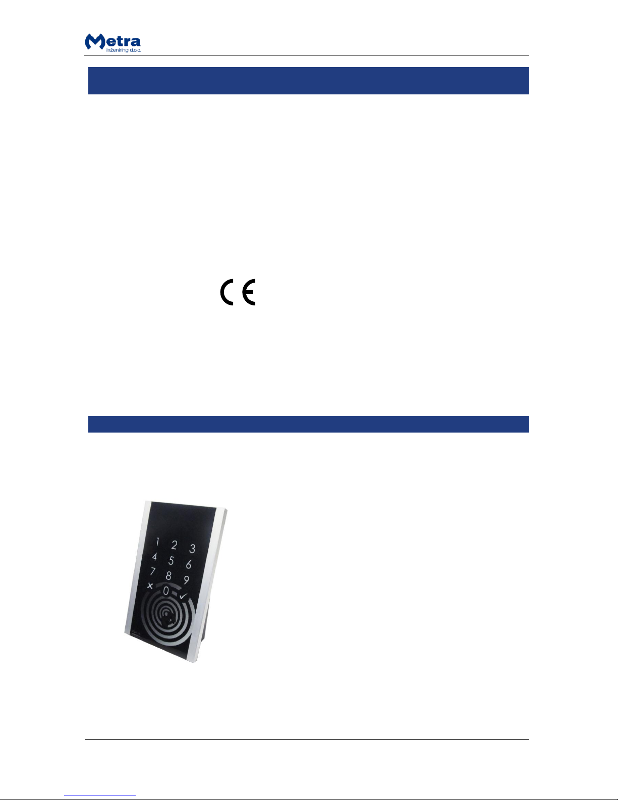
Product description
Door Access Terminal Combo (DAT Combo) is designed to
form a one-way check point in Metra Access Control
Systems and Electronic Locking Systems.
In Access Control Systems a RFID media is used as a door
key. For higher security (e.g. outside door, etc.) a user
specific PIN code as an addition to RFID media can be used.
In Electronic locking systems a RFID media or a locker
number followed by a locker’s PIN code can be used as a
door key.
When access is granted device gives a single relay signal for
access mechanisms such as electric door strike, automatic
door, etc. Normally it is mounted near door where passage
control is needed.
Door Access Terminal operates on line with Metra software.
It must be connected to Metra NET Network.
Passage on Door Access Terminal Combo for particular RFID
ticket can also be externally controlled by 3rd party SW via
TCP/IP software interface.
Operating parameters are defined in the Metra software.
Event data from device is used for further analyses with this
software.
Page 4
Page 4
Door Access Terminal Combo Technical Manual
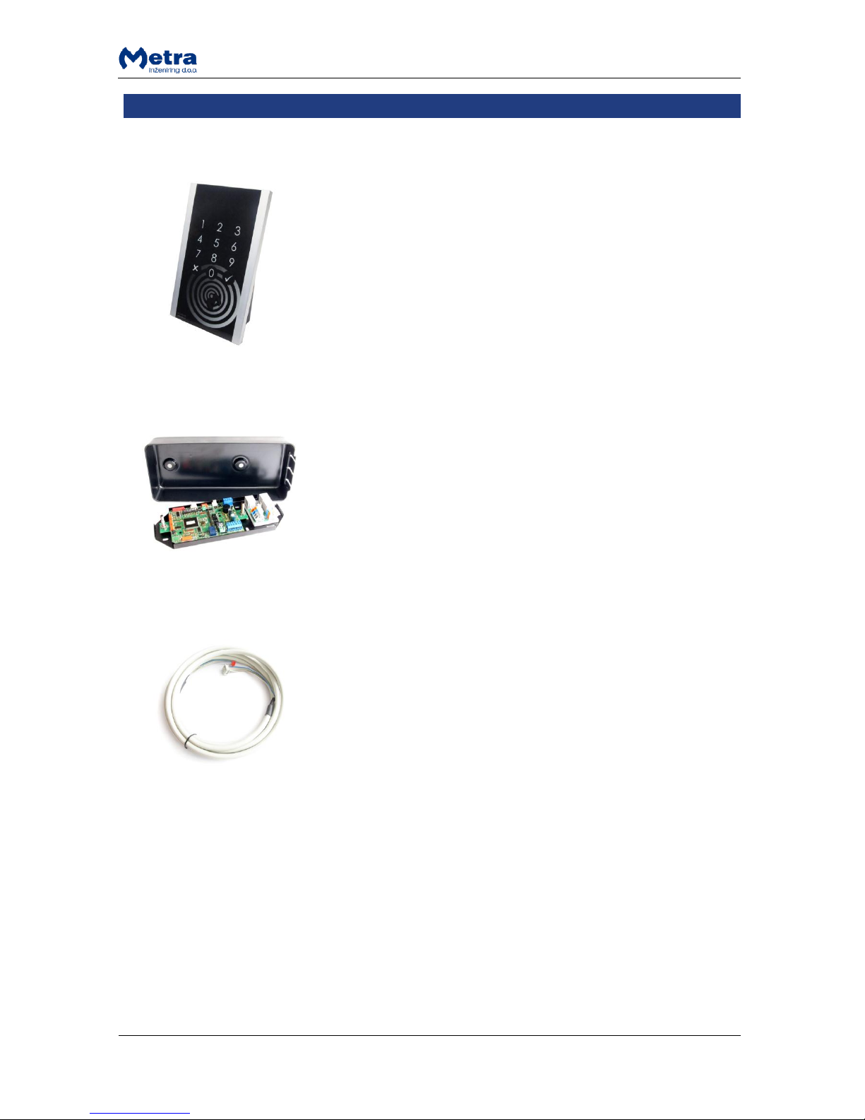
Basic Parts
Door Access Terminal Combo user interface
Door Access Terminal Combo control module
6 pole connection cable
6 pole round to flat cable used to connect Door Access Terminal
user interface to the control module.
Length: 3 m
Page 5
Page 5
Door Access Terminal Combo Technical Manual
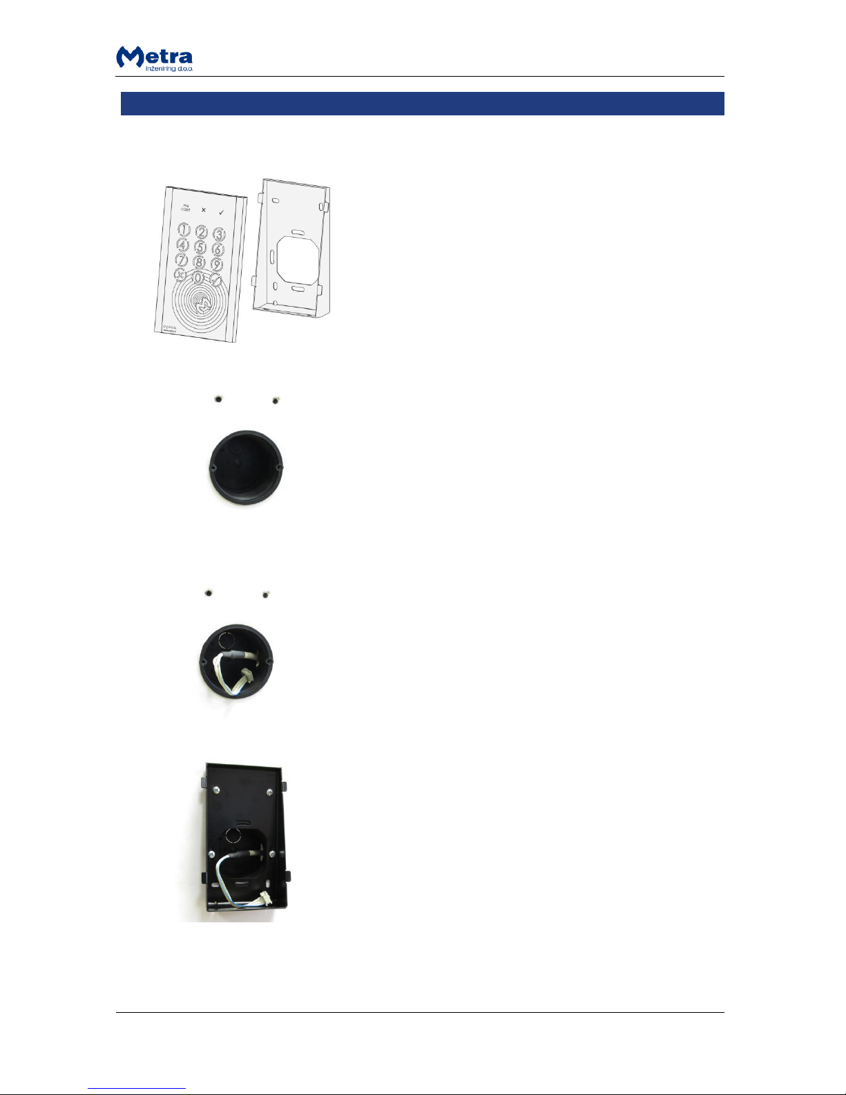
Installation
User interface
STEP 1: User interface can be mounted over an electrical
box or directly to the wall.
See appendices for exact dimensions and mounting holes
positions for the user interface.
STEP 2: Thread the connection wire to the installation
point.
STEP 3: With at least 4 screws attach the metal wall mount
to the wall.
NOTE: Screws are not supplied.
Page 6
Page 6
Door Access Terminal Combo Technical Manual
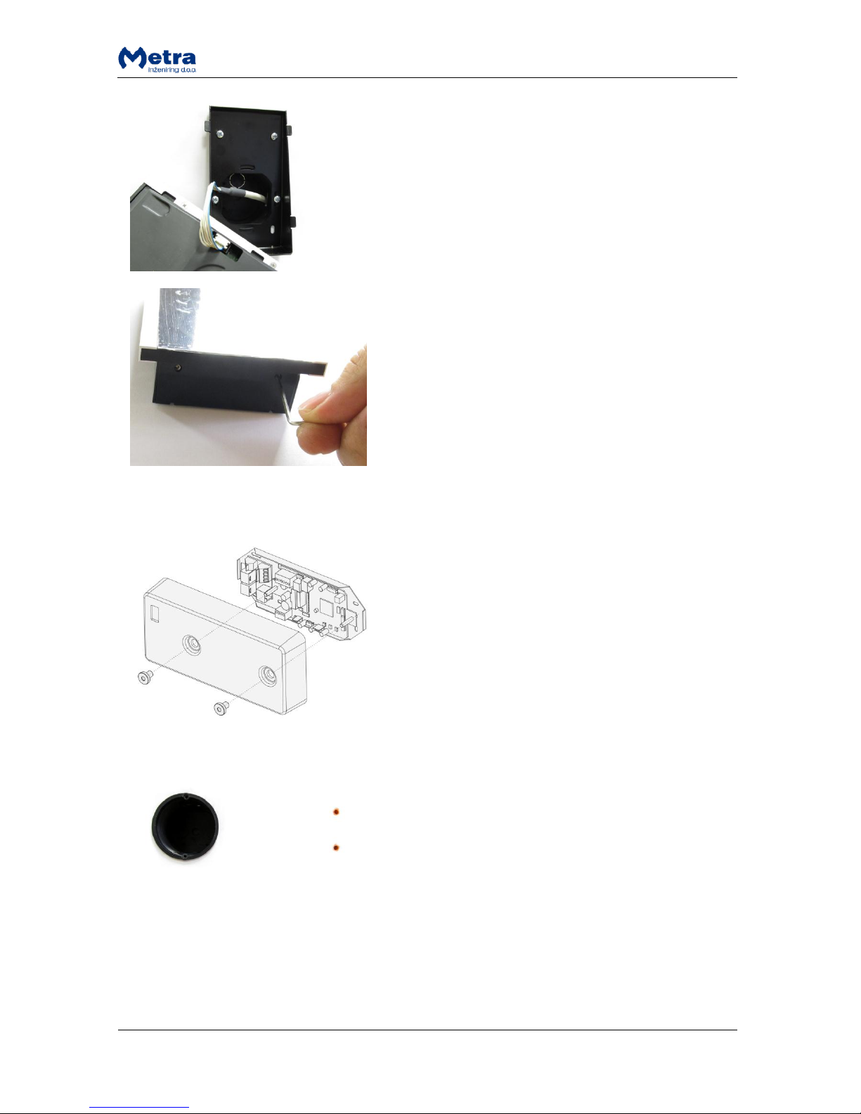
STEP 4: Connect the cable from the control module to the
connector on the back of the user interface device.
STEP 5: Attach the user interface to the metal wall mount
and with 2mm hex screwdriver / inbus key lock it in place.
Rotate the screws counter clockwise.
NOTE: Remove the protective film from the foil.
Control module
STEP 1: Control module can be mounted over an electrical
box or directly to the wall.
See appendices for exact dimensions and mounting holes
positions for the control module.
Page 7
Page 7
Door Access Terminal Combo Technical Manual
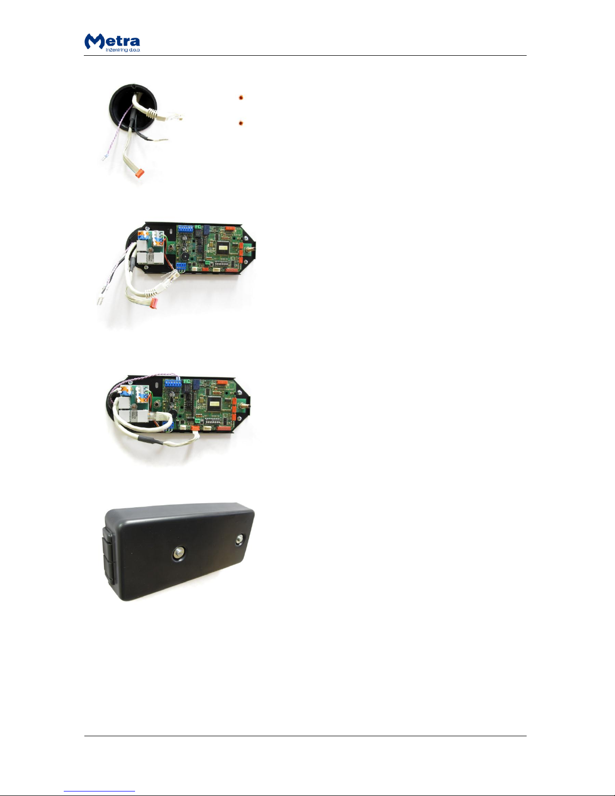
STEP 2: Thread the wires (power, network, door lock, etc.)
to the installation point.
NOTE: Example on the photo shows wires for Metra NET
Network, power, connection cable for user interface and
electronic door lock.
STEP 3: Attach the control module to the surface.
If mounted over an electrical box use the hole on the side
to wire cables thru it.
STEP 4: Connect the cables to the control module. For
details see next chapter. Attach the front with 4 supplied
screws.
STEP 5: With two supplied screws attach the front cover.
Page 8

Page 8
Door Access Terminal Combo Technical Manual
Connections
User interface
#
description
1
User interface – control module communication
Control module
#
description
#
description
1
Metra NET Network
8 Not Used
Page 9

Page 9
Door Access Terminal Combo Technical Manual
2
Power 12V DC
9 Not Used
3
Door Lock / Tamper sensor / Push-button
10
Extension Relay Module (I2C bus)
4
Not Used
11
User interface
5
Not Used
12
Serial RS-232
6
Not Used
13
Metra NET Network
7
BDM Loader
14
Metra NET Network
Power supply connection
Regulated DC power supply is required for proper operation. See chapter “Technical data” for power
requirements.
Connect 12V DC regulated power supply to designated
terminals on the Control Module’s integrated Network
Splitter. The terminals are marked as +12V for positive
connection and GND for ground connection.
WARNING
Mind the polarity! Wrong polarity could result in
irreparable damage to the device.
Respect power requirements data! Using unsuitable
power supply could result in damage to the power
supply and to the device.
Metra NET Network connection
The Metra NET Network connection provides for operational functionality of the Door Access
Terminal Combo.
Different devices in parallel can be connected to the Metra Network Controller by a single unshielded
twisted pair (UTP) cable. Total length of the twisted pair cable is limited to 1 km. One Network Line
Terminator must be connected at the far end of the network cable. See also “Metra NET Network –
Installation Manual” for different wiring schemes.
Connect the UTP Metra NET network cable to one of the
designated terminals on the Control Module’s integrated
Network Splitter. The terminals are marked “RJ45“.
NOTE
Do not confuse Metra NET Network connection with
computer LAN network.
Page 10

Page 10
Door Access Terminal Combo Technical Manual
User interface connection
CONTROL MODULE
Connect the connection cable to the terminal marked
“READER”.
USER INTERFACE
Connect the connection cable to the terminal marked
“READER IN”.
Electronic door lock connection
Set the relay output jumpers on the device or on the relay module according your electronic door
lock.
Connect the electronic door lock to the terminals marked “RELE” on the control module.
WARNING
Mind the power polarity if one of the options with DC output is selected – see corresponding
schematics. Wrong polarity could result in irreparable damage to the device.
WARNING
Mind the electronic door lock power consumption. 12 V
DC door lock with max 0.5 A current consumption can be
connected directly to the device. Use additional relay
module for electronic door locks with higher current
consumption.
Page 11

Page 11
Door Access Terminal Combo Technical Manual
Tamper sensor connection
Connect the tamper switch cable to the terminals marked
“TAMP” on the control module.
Push-button connection
Connect the cable from “normally open” Push-button to
the terminals marked “TIPKA” on the control module.
Page 12

Page 12
Door Access Terminal Combo Technical Manual
DIP switch settings
#
description
1
DIP switch
2
Parameters request button
By changing the DIP Switch pins position, different operating modes and device’s Metra NET
Network address can be set. To change between different pins positions, use a small flat headed
screwdriver or similar object to push DIP switch pins to desired position.
After each settings DIP switch position change power off and back on the device (for the new settings
to take effect).
Network address
After installation is complete, the device network address must be set by DIP switches.
NOTE
Each Metra device must have different address setting.
Switch #1 must be set to OFF (switch down).
Look up the code for desired network address in the coding table. Set switches #2 through #8 to
indicated positions, where:
0 indicates the corresponding switch is in OFF position (switch down)
Page 13

Page 13
Door Access Terminal Combo Technical Manual
1 indicates the corresponding switch is in ON position (switch up)
Coding table:
switch positions
address
switch positions
address
2 3 4 5 6 7 8 2 3 4 5 6 7 8
0 0 0 0 0 0 0
200
1 0 0 0 0 0 0 264
0 0 0 0 0 0 1
201
1 0 0 0 0 0 1 265
0 0 0 0 0 1 0
202
1 0 0 0 0 1 0 266
0 0 0 0 0 1 1
203
1 0 0 0 0 1 1 267
0 0 0 0 1 0 0
204
1 0 0 0 1 0 0 268
0 0 0 0 1 0 1
205
1 0 0 0 1 0 1 269
0 0 0 0 1 1 0
206
1 0 0 0 1 1 0 270
0 0 0 0 1 1 1
207
1 0 0 0 1 1 1 271
0 0 0 1 0 0 0
208
1 0 0 1 0 0 0 272
0 0 0 1 0 0 1
209
1 0 0 1 0 0 1 273
0 0 0 1 0 1 0
210
1 0 0 1 0 1 0 274
0 0 0 1 0 1 1
211
1 0 0 1 0 1 1 275
0 0 0 1 1 0 0
212
1 0 0 1 1 0 0 276
0 0 0 1 1 0 1
213
1 0 0 1 1 0 1 277
0 0 0 1 1 1 0
214
1 0 0 1 1 1 0 278
0 0 0 1 1 1 1
215
1 0 0 1 1 1 1 279
0 0 1 0 0 0 0
216
1 0 1 0 0 0 0 280
0 0 1 0 0 0 1
217
1 0 1 0 0 0 1 281
0 0 1 0 0 1 0
218
1 0 1 0 0 1 0 282
0 0 1 0 0 1 1
219
1 0 1 0 0 1 1 283
0 0 1 0 1 0 0
220
1 0 1 0 1 0 0 284
0 0 1 0 1 0 1
221
1 0 1 0 1 0 1 285
0 0 1 0 1 1 0
222
1 0 1 0 1 1 0 286
0 0 1 0 1 1 1
223
1 0 1 0 1 1 1 287
0 0 1 1 0 0 0
224
1 0 1 1 0 0 0 288
0 0 1 1 0 0 1
225
1 0 1 1 0 0 1 289
0 0 1 1 0 1 0
226
1 0 1 1 0 1 0 290
0 0 1 1 0 1 1
227
1 0 1 1 0 1 1 291
0 0 1 1 1 0 0
228
1 0 1 1 1 0 0 292
0 0 1 1 1 0 1
229
1 0 1 1 1 0 1 293
0 0 1 1 1 1 0
230
1 0 1 1 1 1 0 294
0 0 1 1 1 1 1
231
1 0 1 1 1 1 1 295
0 1 0 0 0 0 0
232
1 1 0 0 0 0 0 296
0 1 0 0 0 0 1
233
1 1 0 0 0 0 1 297
0 1 0 0 0 1 0
234
1 1 0 0 0 1 0 298
0 1 0 0 0 1 1
235
1 1 0 0 0 1 1 299
0 1 0 0 1 0 0
236
1 1 0 0 1 0 0 300
0 1 0 0 1 0 1
237
1 1 0 0 1 0 1 301
0 1 0 0 1 1 0
238
1 1 0 0 1 1 0 302
0 1 0 0 1 1 1
239
1 1 0 0 1 1 1 303
0 1 0 1 0 0 0
240
1 1 0 1 0 0 0 304
0 1 0 1 0 0 1
241
1 1 0 1 0 0 1 305
0 1 0 1 0 1 0
242
1 1 0 1 0 1 0 306
0 1 0 1 0 1 1
243
1 1 0 1 0 1 1 307
0 1 0 1 1 0 0
244
1 1 0 1 1 0 0 308
0 1 0 1 1 0 1
245
1 1 0 1 1 0 1 309
0 1 0 1 1 1 0
246
1 1 0 1 1 1 0 310
Page 14

Page 14
Door Access Terminal Combo Technical Manual
0 1 0 1 1 1 1
247
1 1 0 1 1 1 1 311
0 1 1 0 0 0 0
248
1 1 1 0 0 0 0 312
0 1 1 0 0 0 1
249
1 1 1 0 0 0 1 313
0 1 1 0 0 1 0
250
1 1 1 0 0 1 0 314
0 1 1 0 0 1 1
251
1 1 1 0 0 1 1 315
0 1 1 0 1 0 0
252
1 1 1 0 1 0 0 316
0 1 1 0 1 0 1
253
1 1 1 0 1 0 1 317
0 1 1 0 1 1 0
254
1 1 1 0 1 1 0 318
0 1 1 0 1 1 1
255
1 1 1 0 1 1 1 319
0 1 1 1 0 0 0
256
1 1 1 1 0 0 0 320
0 1 1 1 0 0 1
257
1 1 1 1 0 0 1 321
0 1 1 1 0 1 0
258
1 1 1 1 0 1 0 322
0 1 1 1 0 1 1
259
1 1 1 1 0 1 1 323
0 1 1 1 1 0 0
260
1 1 1 1 1 0 0 324
0 1 1 1 1 0 1
261
1 1 1 1 1 0 1 325
0 1 1 1 1 1 0
262
1 1 1 1 1 1 0 326
0 1 1 1 1 1 1
263
1 1 1 1 1 1 1 327
Operating indicator
When the unit is running a blue OPERATE signal light is flashing. Keypad illumination is ON or OFF,
depending on the type of the system.
OR
Metra Electronic locking systems
Metra Access Control systems with
PIN only functionality
Metra Access Control systems
Page 15

Page 15
Door Access Terminal Combo Technical Manual
Signalization lights
#
description
#
description
1
PIN CODE signal
4 Keypad illumination
2
NO signal
5 OPERATE (Power) signal
3
OK signal
For more about signalization lights see “Door Access Terminal Combo – User Manual.pdf”.
Operating parameters
Parameter
Value (Default)
Description
Signal Time
1 – 30 (6)
Signalization duration in seconds.
Relay Activation
Duration
0 – 30 (6)
Relay activated for X seconds. 0 = 50ms pulse.
Relay Activation
Latch/Unlatch
ON/OFF (OFF)
Latch/Unlatch function
Page 16

Page 16
Door Access Terminal Combo Technical Manual
Relay Mode
El. Strike/Metra 3R
(El. Strike)
Type of relay used.
Alarm
Device Break-In
ON/OFF (OFF)
Not supported.
Alarm
Door opened longer
than
ON: 31 – 600 (60)/OFF
(OFF)
Alarm is triggered if the door stays opened for X
seconds.
Alarm
Door Break-In
ON/OFF (OFF)
Alarm is triggered if the door is opened by force.
Alarm
Alarm Time
1 – 180 (30)
Alarm duration in seconds.
Pushbutton input
ON/OFF (OFF)
Door can be opened by pressing the pushbutton.
Pushbutton must be installed and connected.
Time Checking
ON (From: 00:00-23:59 –
to: 00:00-23:59) per each
day of week/OFF (OFF)
Entrance with user card is possible from XX:XX to
XX:XX if time checking is ON. If set to OFF,
entrance is always possible.
Lockers
ON (1-9999)/OFF (OFF)
Entrance with user card is possible if user card
has one or more set lockers assigned to it.
There are various ways of setting the operating parameters.
Setting Operational parameters - via Metra NET Network
Operating parameters are obtained through the Metra NET Network. The server must be set up and
running for that purpose. To obtain operating parameters, press the PARAMETERS REQUEST button
(number in the paragraph “DIP switch settings”).
NOTE
Network based functionality will be present only if the server is running and the Door Access
Terminal has been properly configured.
NOTE
Metra software automatically updates operating parameters on the device if you change them.
Setting Operational parameters - via serial port by PC
You can download the operating parameters from the template file with LCC Download
software.
Consult LCC Download Software User Manual for more information.
Maintenance
No regular maintenance is needed.
Page 17

Page 17
Door Access Terminal Combo Technical Manual
Regular cleaning is recommended. The user interface should be cleaned using soft cloth
and dedicated cleaners for plastic surfaces e.g. car dashboard cleaning agents. Do not use
any aggressive or abrasive agents or solvents as they might cause permanent damage to
the device surface.
Technical data
Operating voltage
12V DC regulated (11.5 – 15V DC tolerated)
Current consumption
0.50 A
Operating temperature range
-10 to +50 °C
Audio signal
integrated piezoelectric beeper
Visual signalization
3 LEDs.
Network type
CAN network interface to Network Controller
Appendix
1
Physical dimensions
User interface
2
Physical dimensions
Control module
3
Physical dimensions
User interface mounting holes
4
Physical dimensions
Control module mounting holes
5
Inner connections
6
Electric installation schematic
Page 18

Appendix 1Door Access Terminal Combo
Physical dimensions
User interface
89
147.237
148
10°
Page 19

Appendix 2Door Access Terminal Combo
Physical dimensions
Control module
40
232
105 40
232
105
Page 20

Appendix 3Door Access Terminal Combo
Physical dimensions
User interface mounting holes
8
60
90
52
60
Page 21

Appendix 4Door Access Terminal Combo
Physical dimensions
Control module mounting holes
60
30120
157
36.7
Page 22

Appendix 5Door Access Terminal
Inner connections
1 2 53 4 6 7 8
Page 23

installation hose
(PVC 16 mm)
2
4 x 0.5 mm
(2 + 2 optional)
DAT Control Module
CAN Network in
CAN Network out
Supplied
6 pole
connection
cable
Door Sensor (opt.)
Electric Lock
UTP CAT5
UTP CAT5
12V DC in
12 V DC
must be prepared
by a certified electrician!
12V DC to other units
2
2 x 0.5 mm
Appendix 6Door Access Terminal
Electric installation schematic
floor
ceiling
120 - 145 cm
ENTRANCE
DAT User Interface
Gewiss case
GW48003
Standard
Electric Lock
12V / 0.6A
Door Sensor
(optional)
power requirements:
0.5A + electric lock consumption
for each connected unit
 Loading...