

Page 1
Door Access Terminal Combo User Manual
Page 2

Page 2
Door Access Terminal Combo User Manual
Table of contents
Door Access Terminal Combo User Manual ............................................................................................ 3
Product description ............................................................................................................................. 3
Basic Parts ........................................................................................................................................... 4
User Interface...................................................................................................................................... 4
Operating indicator ............................................................................................................................. 5
User card presentation ....................................................................................................................... 6
Passage Allowed ............................................................................................................................. 6
Passage denied ............................................................................................................................... 7
PIN code requested .......................................................................... Error! Bookmark not defined.
Signal not activated ........................................................................................................................ 7
Master card presentation ................................................................................................................. 10
Latch/Unlatch function ..................................................................................................................... 10
User card with permanent option presented ................................... Error! Bookmark not defined.
Master card presented ................................................................................................................. 10
Alarm signalization ............................................................................................................................ 11
Page 3
Page 3
Door Access Terminal Combo User Manual
Door Access Terminal Combo User Manual
Manufacturer:
Metra inženiring d.o.o.
IOC Trzin
Špruha 19
SI-1236 Trzin, Slovenia
phone:
fax:
web:
+386 1 56 10 740
+386 1 56 10 744
www.metra.si
System:
Metra Access Control System
Product Group:
Door Access Terminal Combo
Types:
DLCIS (ISO14443A/B, ISO 15693)
DLCLF (LF Multitag)
DLCMF (Mifare, ISO14443A/B)
Year of Construction:
2011 - 2012
Declaration of Conformity:
Metra Access Control products have been developed, designed and
manufactured in accordance with the EU directive for Electromagnetic
Compatibility (2004/108/EC).
Door Access Terminal Combo User Manual [rev.0-050912]
2012 Metra inženiring d.o.o.
All Rights reserved.
No part of this manual may be reproduced in any form or by any means without prior written permission of Metra inženiring d.o.o.
The contents of this manual are subject to change without notice.
All efforts have been made to ensure the accuracy of the contents of this manual, however, should any errors be detected, Metra inženiring would greatly appreciate being informed of
them. Metra inženiring d.o.o. can assume no responsibility for any errors in this manual.
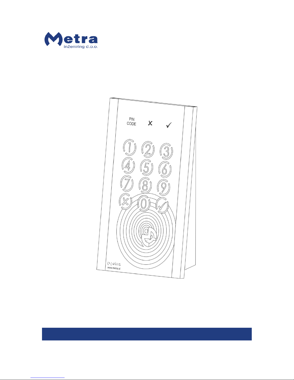
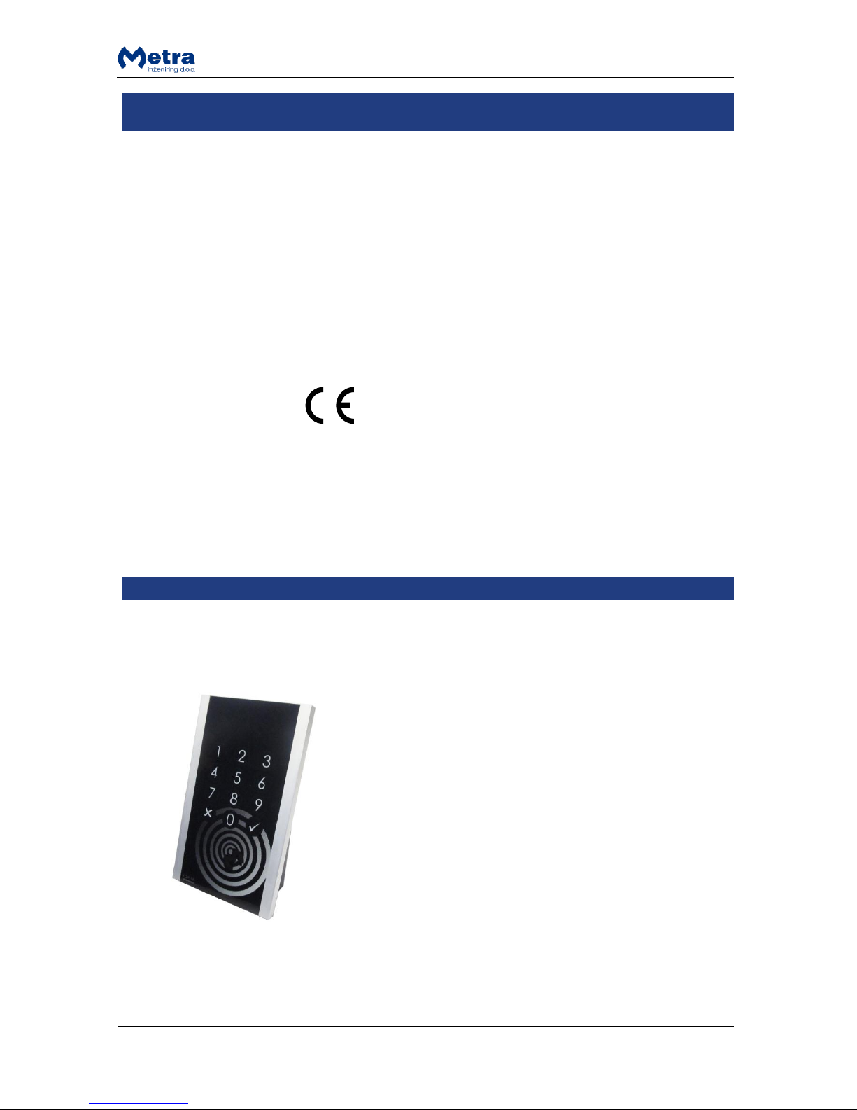
Product description
Door Access Terminal Combo (DAT Combo) is designed to
form a one-way check point in Metra Access Control
Systems and Electronic Locking Systems.
In Access Control Systems a RFID media is used as a door
key. For higher security (e.g. outside door, etc.) a user
specific PIN code as an addition to RFID media can be used.
In Electronic locking systems a RFID media or a locker
number followed by a locker’s PIN code can be used as a
door key.
When access is granted device gives a single relay signal for
access mechanisms such as electric door strike, automatic
door, etc. Normally it is mounted near door where passage
control is needed.
Door Access Terminal operates on line with Metra software.
It must be connected to Metra NET Network.
Passage on Door Access Terminal Combo for particular RFID
ticket can also be externally controlled by 3rd party SW via
TCP/IP software interface.
Operating parameters are defined in the Metra software.
Event data from device is used for further analyses with this
software.
Page 4

Page 4
Door Access Terminal Combo User Manual
Basic Parts
#
description
#
description
1
PIN CODE signal
4 12 key illuminated keypad
2
NO signal
5 OPERATE (Power) signal
3
OK signal
6 Antenna field
Standard models are supplied with front mask in glossy black colour. For additional colours contact
Metra sales.
User Interface
Door Access Terminal user interface uses optical signals ( , , , and ) and an acoustic
beeper signal to inform the user about operation progress. Signals are explained in the following
tables.
NOTE: Keypad’s illumination may be ON or OFF, depending on the type of the system. In some
systems it is OFF by default and lights up when a PIN code is requested and in other systems it is
always ON.
Page 5

Page 5
Door Access Terminal Combo User Manual
OK signal (green)
state
Description
on
passage is enabled (lock is unlocked); accompanied with short beep acoustic signal
NO signal (red)
state
Description
flashing
RFID media is recognized but passage is denied; accompanied with interrupted acoustic
signal
PIN CODE signal (blue)
state
Description
flashing
PIN code is requested; accompanied with interrupted acoustic signal
OPERATE signal (blue)
state
Description
flashing
device operates normally
Operating indicator
When the unit is running a blue OPERATE signal light is flashing. Keypad illumination is ON or OFF,
depending on the type of the system.
OR
Metra Electronic locking systems
Metra Access Control systems with
PIN only functionality
Metra Access Control systems
Page 6

Page 6
Door Access Terminal Combo User Manual
RFID media as a user door key
Approach the card to the antenna field. Reading distance is
3 – 5 centimetres from the device surface. Hold the card in
field for a few moments for Door Access Terminal to read
and process the card.
Short Acoustic signal is activated when the cards is
recognized.
RFID media accepted and passage allowed
When card is accepted, “OK” optical signal lights up and
short acoustic signal is activated.
The door is unlocked.
Remove the card form the antenna filed.
RFID media accepted and PIN code requested
When card is accepted, “PIN CODE” optical signal starts
flashing accompanied with short acoustic signals.
Enter your 4 digit PIN code. By entering the last digit you
automatically confirm the PIN code.
NOTE
Only 4 digit PIN codes are supported by Metra software
user interface.
Page 7

Page 7
Door Access Terminal Combo User Manual
If the PIN code is correct, “OK” optical signal lights up and
short acoustic signal is activated.
The door is unlocked.
If the PIN code is rejected, “NO” optical signal starts flashing
and interrupted acoustic signal is activated for 2 seconds.
Door remains locked.
Passage denied
If the card is rejected (passage not allowed) “NO” optical
signal is flashing and interrupted acoustic signal is
activated for 2 seconds.
Door remains locked.
Remove the card form the antenna filed.
Signal not activated
If there is no optical signal (door remains locked) the
device is not functioning properly. Call maintenance
personnel.
Page 8

Page 8
Door Access Terminal Combo User Manual
PIN code as a LCC user door key
NOTE
This functionality is present only in old Metra LCC systems.
STEP 1: Enter your PIN code and confirm it by pressing the
key.
STEP 2 A: If the PIN code is correct, “OK” optical signal lights
up and short acoustic signal is activated.
The door is unlocked.
STEP 2 B: If the PIN code is rejected, “NO” optical signal
starts flashing and interrupted acoustic signal is activated
for 2 seconds.
Door remains locked.
PIN code as a user door key
This functionality is used in combination with different Metra Electronic Locking Systems for lockers.
PIN code is not used as a standalone key, but always in combination with user’s locker number.
User’s PIN code is also valid as long as he/she has an assigned locker. Once locker expires also user’s
PIN code expires.
Page 9

Page 9
Door Access Terminal Combo User Manual
STEP 1: Enter your locker’s number and confirm it by
pressing the key.
STEP 2 A: If there is no locker with the number you entered
or there is no reservation for this locker in the database
procedure is rejected, “NO” optical signal starts flashing
and interrupted acoustic signal is activated for 2 seconds.
Door remains locked.
STEP 2 B: If there is a valid reservation in the database for
the locker you entered a “PIN CODE” optical signal starts
flashing accompanied with short acoustic signals.
Enter your 4 digit PIN code. By entering the last digit you
automatically confirm the PIN code.
NOTE
Only 4 digit PIN codes are supported by Metra software
user interface.
STEP 3 A: If the PIN code is correct, “OK” optical signal
lights up and short acoustic signal is activated.
The door is unlocked.
STEP 3 B: If the PIN code is rejected, “NO” optical signal
starts flashing and interrupted acoustic signal is activated
for 2 seconds.
Door remains locked.
Page 10

Page 10
Door Access Terminal Combo User Manual
Master card presentation
STEP 1: Approach the MASTER card to the antenna field.
Reading distance is 3 – 5 centimetres from the device
surface. Hold the card in field for a few moments for Door
Access Terminal to read and process the card.
STEP 2: When the MASTER card is recognized, “OK” optical
signal lights up and short acoustic signal is activated.
The door is unlocked.
Remove the card form the antenna filed.
Latch/Unlatch function
Latch/Unlatch function is possible from Metra software or by presenting the Master card.
Functionality allows user to permanently open the door lock for prolonged period of time. This
function is especially useful for conference rooms, maintenance purposes and in emergency cases.
Master card presentation
NOTE
Latch/Unlatch function with Master card is always possible and it cannot be disabled!
STEP 1: Approach the MASTER card to the antenna field.
Reading distance is 3 – 5 centimetres from the device
surface. Hold the card in field for a few moments for Door
Access Terminal to read and process the card.
Page 11

Page 11
Door Access Terminal Combo User Manual
STEP 2: When the MASTER card is recognized, “OK” optical
signal lights up and short acoustic signal is activated.
The door is unlocked.
STEP 3: Do not remove the MASTER card from the
antenna field until additional two short acoustic signals are
activated (approximately 4 seconds after first single
acoustic signal is activated).
The door remains unlocked (latched) and “OK” optical
signal remains on.
Remove the MASTER card form the antenna filed.
NOTE
Repeat the procedure to deactivate (unlatch) the door lock. “OK” optical signal is also deactivated.
Alarm signalization
When Alarm is triggered the interrupted acoustic signal
and “NO” optical signal are activated.
Alarm is triggered by following actions:
Door brake-in is detected.
Door is opened longer than X seconds, while X is set in the operating parameters.
NOTE: For both, the door must be equipped with the tamper sensor and alarm must be enabled in
device’s operating parameters.
Consult Door Access Terminal Technical Manual for details.
 Loading...