

Page 1
INSTALLATION INSTRUCTIONS FOR PART CHTO-013
CHTO-013
Chrysler Amplified Data Interface
2004-up
APPLICATIONS
See inside front cover
KIT FEATURES
• Provides accessory (12-volt 10-amp)
• Retains R.A.P. (Retained Accessory Power)
• Used in amplified systems
• Provides NAV outputs (Parking Brake, Reverse, Mute, V.S.S.)
• Prewired ASWC-1 harness included (ASWC-1 not included)
• High level speaker input
• USB updatable
• Retains balance and fade
INTERFACE COMPONENTS
• CHTO-013 interface • 16-pin harness with stripped leads
• 10-pin harness to 22-pin Chrysler harness with stripped leads
TOOLS REQUIRED
• Cutting tool • Crimping tool • Tape
• Connectors (example: butt-connectors, bell caps, etc.)
IGNITION
TERMINALS
M3.5
ISO
M4
M5
1.5
2.5
6
WIRE
CUTTER
M3
M2.6
METRA. THE WORLD’S BEST KITS.™
1-800-221-0932
© COPYRIGHT 2004-2011 METRA ELECTRONICS CORPORATION
metraonline.com
REV. 6/18/13
Page 2

CHTO-013
Applications
CHRYSLER
200 2011-up
300 2005-2010
Aspen 2007-2009
Sebring 2007-2010
Town & Country 2008-up
DODGE
Avenger 2008-up
Caliber 2007-2010
Challenger 2009-up
Charger 2005-2010
Dakota 2005-up
Durango 2004-up
Grand Caravan 2008-up
Journey 2009-2010
Magnum 2005-2009
Nitro 2007-up
Ram 2006-2012
Ram 2500/3500 2006-2012
JEEP
Commander 2006-2010
Compass 2007-up
Grand Cherokee 2005-2013
Liberty 2008-up
Patriot 2007-up
Wrangler 2007-up
MITSUBISHI
Raider 2006-2009
Caution
any installation. All accessories, switches, and especially air bag indicator lights must be
plugged in before reconnecting the battery or cycling the ignition.
Note: Refer also to the instructions included with the aftermarket radio.
: Metra recommends disconnecting the negative battery terminal before beginning
Page 3

CHTO-013
Connections to be made
From the 16-pin harness:
• Connect the Red wire to the ignition wire of the aftermarket radio.
• Connect the Orange/White wire to the illumination wire of the aftermarket radio.
If the aftermarket radio has no illumination wire just tape off the Orange/White wire.
• Connect the White wire to the left front positive speaker output of the aftermarket radio.
• Connect the White/Black wire to the left front negative speaker output of the
aftermarket radio.
• Connect the Gray wire to the right front positive speaker output of the aftermarket radio.
• Connect the Gray/Black wire to the right front negative speaker output of the
aftermarket radio.
• Connect the Green wire to the radio’s left rear positive speaker output.
• Connect the Green/Black wire to the radio’s left rear negative speaker output.
• Connect the Purple wire to the radio’s right rear positive speaker output.
• Connect the Purple/Black wire to the radio’s right rear negative speaker output.
• Connect the Blue/White wire to the radio’s amp turn on wire.
• Connect the Brown wire to the mute wire of the aftermarket radio. If the aftermarket
radio does not have a mute wire, tape up the Brown wire.
• Connect the Light Green wire to the parking brake wire of the aftermarket
navigation radio.
• Connect the Blue/Pink wire to the VSS or speed sense wire of the aftermarket
navigation radio.
• Connect the Green/Purple wire to the reverse wire of the aftermarket navigation radio.
• Plug the 16-pin harness into the CHTO-013.
3
Page 4

CHTO-013
Connections to be made
From the 22-pin Crysler harness:
• Connect the Yellow wire to the radio’s 12-volt battery or memory wire.
• Connect the Black wire to the radio’s ground wire.
• Plug the 10-pin harness into the CHTO-013.
The 12-pin harness (ASWC plug) will be discussed later in the manual.
Installing the CHTO-013
• With all connections completed to the aftermarket radio, plug the 22-pin harness
into the vehicles wiring harness.
• Reconnect the negative battery terminal.
• Cycle the key, by turning the ignition on for 30 seconds. Then off and on
again to test the radio.
Testing the CHTO-013
• Turn the ignition on if not already, and then turn the radio on to verify that the radio
works. Check balance and fader controls for proper operation.
• To adjust the overall volume of your audio system, rotate the potentiometer which is
located on the 16-pin side of the interface clockwise.
Additional 12-pin harness (ASWC harness)
This 12-pin harness is to be used in conjunction with the ASWC (not included).
Please refer to ASWC instructions for programming.
4
Page 5
CHTO-013
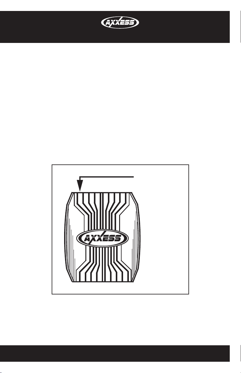
Audio Level Control
1. Make sure the ignition is turned to the “off” position.
2. Disconnect both of the harnesses from the CHTO-013.
3. Locate the potentiometer next to the 16-pin connector at the end of the CHTO-013.
4. Taking a small flat headed screwdriver, turn the potentiometer counter-clockwise to lower
the input level going to the factory amplifier.
5. After making the adjustment reconnect the wire harnesses.
Potentiometer Audio
POTENTIOMETER
Level Adjustment
AUDIO LEVEL
ADJUSTMENT
5
Page 6

Notes
Page 7

Notes
Page 8

INSTALLATION INSTRUCTIONS FOR PART CHTO-013
IMPORTANT WARNING
This product includes instructions for installation which must be carefully
followed. The instructions are worded in such a manner to assume
that the installer is capable of completing these type of electronic
installations. If you are unclear as to what you are instructed to do or
believe that you do not understand the instructions so as to properly and
safely complete the installation you should consult a technician who
does have this knowledge and understanding.
Failure to follow these instructions carefully and to install the
interface as described could cause harm to the vehicle or to safety
systems on the vehicle. Interference with certain safety systems
could cause harm to persons as well. If you have any questions in
this regard please call the Help line or Metra at
1-800-221-0932 for assistance.
REV. 6/18/13
KNOWLEDGE IS POWER
Enhance your installation and fabrication skills by
enrolling in the most recognized and respected
mobile electronics school in our industry.
Log onto www.installerinstitute.com or call
800-354-6782 for more information and take steps
toward a better tomorrow.
Metra recommends MECP
certified technicians
METRA. THE WORLD’S BEST KITS.™
1-800-221-0932
metraonline.com
© COPYRIGHT 2004-2011 METRA ELECTRONICS CORPORATION
Page 9

INSTRUCCIONES DE INSTALACIÓN PARA LA PIEZA CHTO-013
CHTO-013
Amplificada interfaz de datos de para
Chrysler2004 y más recientes
apliCaCiones
Lista de aplicaciones dentro
CaraCterístiCas del kit
• Proporciona accesorio (12 voltios 10 amperes)
• Retiene R.A.P. (Corriente de accesorio retenida)
• Se usa en sistemas amplificados
• Proporciona salidas de NAV (freno de mano, reversa, silencio, V.S.S.)
• Precableado ASWC-1 arnés incluido (ASWC-1 no incluido)
• Entrada de bocina de alto nivel
• Adaptable a USB
• Retiene el balance y la intensidad
Componentes de la interfaz
• Interfaz CHTO-013 • Arnés de 16 pins con conectores pelados • Arnés de
10 pins a arnés Chrysler de 22 pins con conectores pelados
Herramientas requeridas
• Herramientas de corte • Herramienta engarzadora • Cinta
• Conectores (p. ej., conectores a tope, tapas acampanadas, etc.)
IGNITION
TERMINALS
M3.5
ISO
M4
M5
1.5
2.5
6
WIRE
CUTTER
M3
M2.6
METRA. THE WORLD’S BEST KITS.™
1-800-221-0932
© COPYRIGHT 2004-2011 METRA ELECTRONICS CORPORATION
metraonline.com
REV. 6/18/13
Page 10

CHTO-013
Aplicaciones
CHRYSLER
200 2011 y más recientes
300 2005-2010
Aspen 2007-2009
Sebring 2007-2010
Town & Country 2008 y más recientes
DODGE
Avenger 2008 y más recientes
Caliber 2007-2010
Challenger 2009 y más recientes
Charger 2005-2010
Dakota 2005 y más recientes
Durango 2004 y más recientes
Grand Caravan 2008 y más recientes
Journey 2009-2010
Magnum 2005-2009
Nitro 2007 y más recientes
Ram 2006-2012
Ram 2500/3500 2006-2012
JEEP
Commander 2006-2010
Compass 2007 y más recientes
Grand Cherokee 2005-2013
Liberty 2008 y más recientes
Patriot 2007 y más recientes
Wrangler 2007 y más recientes
MITSUBISHI
Raider 2006-2009
PRECAUCIÓN
comenzar cualquier instalación. Todos los accesorios, interruptores y, especialmente, las
luces indicadoras de airbag deben estar enchufados antes de volver a conectar la batería o
comenzar el ciclo de ignición.
Nota: Remítase a las instrucciones incluidas con el radio de postventa.
: Metra recomienda desconectar el terminal negativo de la batería antes de
Page 11

CHTO-013
Conexiones que se deben hacer
Desde el arnés de 16 pins:
• Conecte el cable Rojo con el cable de ignición del radio de mercado secundario.
• Conecte el cable Anaranjado/Blanco con el cable de iluminación del radio de mercado
secundario. Si el radio de mercado secundario no tiene cable de iluminación solo cubra
con cinta el alambre Anaranjado/Blanco.
• Conecte el cable Blanco con la salida de la bocina positiva frontal izquierda del radio de
mercado secundario
• Conecte el cable Blanco/Negro con la salida de la bocina negativa frontal izquierda del
radio de mercado secundario
• Conecte el cable Gris con la salida de la bocina positiva frontal derecha del radio de
mercado secundario
• Conecte el cable Gris/Negro con la salida de la bocina negativa frontal derecha del
radio de mercado secundario
• Conecte el cable Verde con la salida de la bocina positiva izquierda de atrás del radio.
• Conecte el cable Verde/Negro con la salida de la bocina negativa izquierda de
atrás del radio.
• Conecte el cable Púrpura con la salida de la bocina positiva derecha de atrás del radio.
• Conecte el cable Púrpura/Negro con la salida de la bocina negativa derecha de
atrás del radio.
• Conecte el cable Azul/Blanco con el cable de encendido del amplificador
• Conecte el cable Café con el cable de silencio del radio de mercado secundario. Si el
radio de mercado secundario no tiene un cable de silencio, encinte el cable Café.
• Conecte el cable Verde claro con el cable del freno de mano del radio de navegación
de mercado secundario.
• Conecte el cable Azul/Rosa con el cable VSS o de detección de velocidad del radio de
navegación de mercado secundario.
• Conecte el cable Verde/Púrpura con el cable de la reversa del radio de
mercado secundario.
• Conecte el arnés de 16 pins en el CHTO-013.
3
Page 12

CHTO-013
Conexiones que se deben hacer
Desde el arnés Chrysler de 22 pins:
• Conecte el cable Amarillo a la batería de 12 voltios o el cable de memoria del radio.
• Conecte el cable Negro con el cable de puesta a tierra del radio.
• Conecte el arnés de 10 pins en el CHTO-013.
El arnés de 12 pins (conector ASWC) se explicará más adelante en el manual.
Instalación del CHTO-013
• Cuando termine de hacer todas las conexiones en el radio de mercado secundario,
conecte el arnés de 22 pins en el arnés de cables del vehículo.
• Reconecte la terminal de la batería negativa.
• Cicle la llave, encendiendo la ignición durante 30 segundos. Después apague y encienda
de nuevo para probar el radio.
Prueba del CHTO-013
• Prenda la ignición si no lo ha hecho, y después prenda el radio para probar si funciona.
Revise que funcionen bien los controles de balance e intensidad.
• Para ajustar el volumen general de su sistema de audio, gire hacia la derecha el
potenciómetro que está del lado de los 16 pins de la interfaz.
Arnés de 12 pins adicional (arnés ASWC)
Este arnés de 12 pins se debe usar junto con el ASWC (no incluido).
Consulte las instrucciones de ASWC para la programación.
4
Page 13

CHTO-013
Control de nivel de audio
1. Asegúrese de que la llave esté en la posición “apagado”.
2. Desconecte los dos arneses del CHTO-013.
3. Localice el potenciómetro junto al conector de 16 pins en el extremo del CHTO-013.
4. Tomando un pequeño destornillador de paleta, gire el potenciómetro hacia la izquierda
para bajar el nivel de entrada que entra al amplificador de fábrica.
5. Después de hacer el ajuste, reconecte los arneses de cables.
Potenciómetro
POTENTIOMETER
de ajuste del nivel
AUDIO LEVEL
de audio
ADJUSTMENT
5
Page 14

Notas
Page 15

Notas
Page 16

INSTRUCCIONES DE INSTALACIÓN PARA LA PIEZA CHTO-013
KNOWLEDGE IS POWER
Enhance your installation and fabrication skills by
enrolling in the most recognized and respected
mobile electronics school in our industry.
Log onto www.installerinstitute.com or call
800-354-6782 for more information and take steps
toward a better tomorrow.
ADVERTENCIA IMPORTANTE
Este producto incluye instrucciones de instalación que deben seguirse
cuidadosamente. Dichas instrucciones están redactadas dando por
supuesto que el instalador es capaz de completar estos tipos de
instalaciones electrónicas. Si tiene dudas respecto de lo que se le
indica que haga o cree que no comprende las instrucciones como para
completar la instalación en forma adecuada y segura, debe consultar a
un técnico que efectivamente tenga estos conocimientos y comprensión.
Si no sigue estas instrucciones con cuidado y no instala la
interfaz como se describe, podría provocar daños en el vehículo
o en los sistemas de seguridad del vehículo. La interferencia con
determinados sistemas de seguridad también podría provocar
daños a las personas. Si tiene alguna pregunta al respecto,
llame a la línea de ayuda o a metra, al 1-800-221-0932 para
obtener asistencia.
REV. 6/18/13
METRA. THE WORLD’S BEST KITS.™
1-800-221-0932
© COPYRIGHT 2004-2011 METRA ELECTRONICS CORPORATION
EL CONOCIMIENTO ES PODER
Mejore sus habilidades de instalación y fabricación
inscribiéndose en la escuela de dispositivos
electrónicos móviles más reconocida y respetada de
nuestra industria. Regístrese en www.installerinstitute.
com o llame al 800-354-6782 para obtener más
información y avance hacia un futuro mejor.
Metra recomienda técnicos con
certificación del Programa de
Certificación en Electrónica Móvil
(Mobile Electronics Certification
Program, MECP).
metraonline.com
 Loading...