

Page 1
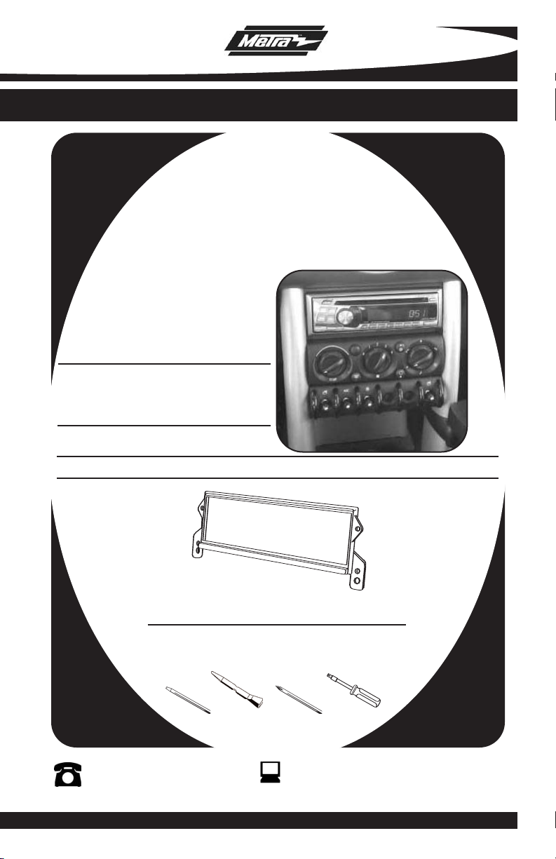
INSTALLATION INSTRUCTIONS FOR PART 99-9302
APPLICATIONS
BMW
Mini Cooper/Cooper S 2002-2007
99-9302
KIT FEATURES
• Mounting bracket
KIT COMPONENTS
A) Mounting Bracket
A
TOOLS REQUIRED:
Small Flat Blade Screwdriver/ Panel Removal Tool
• Phillips Screwdriver • T-33 Torx Driver
1-800-221-0932
© COPYRIGHT 2004-07 METRA ELECTRONICS CORPORA
www.metr
aonline.com
TION
Page 2

99-9302
TABLE OF CONTENTS
Dash Disassembly
-
BMW Mini Cooper/Cooper S 2002-2007 . . . . . . . .
. . . . . . . 1,2
Kit Assembly
- DIN Mount Radio Provision . . . . . . . . . . . . . . . . . . . . . . . . . . . . . . . . . 3
Assembly . . . . . . . . . . . . . . . . . . . . . . . . . . . . . . . . . . . . . . . . . . .4
Final
*Note:
Refer also to the instructions included with the aftermarket radio.
Page 3
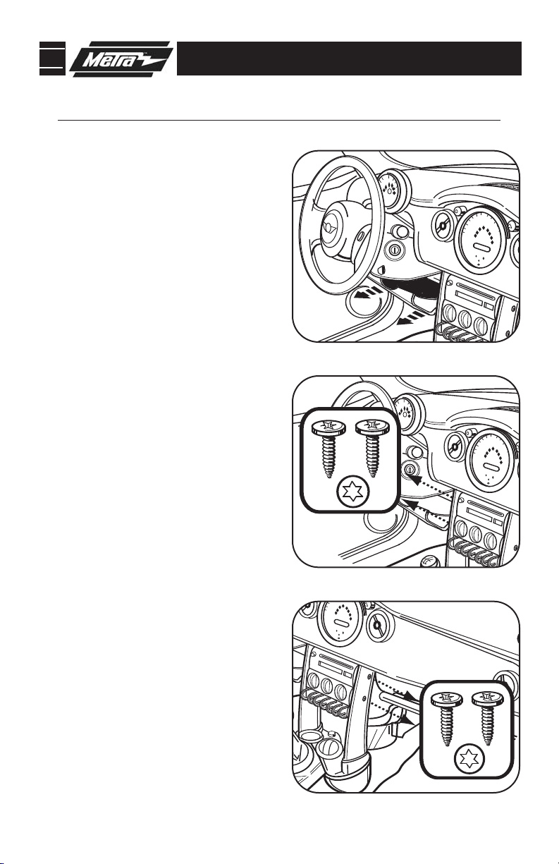
99-9302 DASH DISASSEMBLY
BMW Mini Cooper/Cooper S 2002-2007
Disconnect the negative battery ter-
1
minal to prevent an accidental short
circuit.
Carefully pry out both top edges of
2
driver’s knee panel and allow panel to
hang. (
Figure A)
Remove (2) Torx T-33 screws from
3
driver’s side rail trim.
Remove (2) Torx T-33 screws from
4
passenger side rail trim. (On specially
equipped models, it may be necessary
to open the glove box to access these
(2) screws)
(Figure C)
(Figure B)
A
B
C
1
Page 4

99-9302 DASH DISASSEMBLY
BMW Mini Cooper/Cooper S 2002-2007
Remove (1) Phillips scew from each
5
cup holder. (
Carefully pry up mirror adjustment
6
switch panel and remove (2) Phillips
screws. (
Slide cup holder/gear shift assembly
7
toward rear of car and carefully
remove side rail trims.
Remove (4) Phillip screws securing
8
radio. Pull out radio, disconnect and
remove.
Figure D)
Figure E)
(Figure F)
(Figure G)
D
E
G
F
2
Page 5

99-9302 KIT ASSEMBLY
DIN MOUNT RADIO PROVISION
*Note: Refer also to the instructions included with the aftermarket radio.
A
Slide the DIN cage into the radio open-
1
ing of the Radio Housing and secure by
bending the metal locking tabs out-
(Figure A)
ward.
Slide the aftermarket radio unit into the
2
cage until it snaps into place.
Continue to final assembly.
(Figure B)
B
3
Page 6

99-9302 FINAL ASSEMBLY
FINAL ASSEMBLY
A
(A) Strip wire ends back 1/2"
B
B) Twist ends together
C) Solder
C
D
Locate the factory wiring harness in the dash. Metra recommends using the
1
proper mating adapter and making connections as shown. (Isolate and individually tape off the ends of any unused wir
Re-connect the negative battery terminal and test the unit for proper operation.
2
Reassemble radio and dash assemblies in reverse order of disassembly.
3
D) Tape
es to prevent electrical short circuit.)
FINAL WIRING CONNECTIONS
Make wiring connections using the EIA color code chart shown below and the instructions included with the
head unit. Metra recommends making connections as shown below; Strip, Splice, Solder, Tape. Isolate and
individually tape off ends of any unused wires to prevent electrical short circuit.
METRA / EIA WIRING CODE
12V Ignition / Acc . . . . . . . . . . Red
12V Batt / Memory. . . . . . . . . Yellow
Ground. . . . . . . . . . . . . . . . . . Black*
Power Antenna. . . . . . . . . . . . Blue
Amp Turn-On . . . . . . . . . . . . . Blue / White
Amp Ground. . . . . . . . . . . . . . Black / White
Illumination . . . . . . . . . . . . . . Orange
Dimmer . . . . . . . . . . . . . . . . . Orange / White
Right Front (+) . . . . . . . . . . . . Gray
Right Front (-). . . . . . . . . . . . . Gray/ Black
Left Front (+) . . . . . . . . . . . . . White
Left Front (-). . . . . . . . . . . . . . White / Black
Right Rear (+) . . . . . . . . . . . . Violet
Right Rear (-) . . . . . . . . . . . . . Violet / Black
Left Rear (+)
Left Rear (-) . . . . . . . . . . . . . . Green / Black
. . . . . . . . . . . . .
Green
*NOTE: When a Black wire is not present, ground radio to vehicle chassis.
All colors may not be present on all leads due to manufacturer’s specifications.
4
Page 7

99-9302
NOTES
5
Page 8

99-9302 INSTRUCTIONS
1-800-221-0932
REV. 06/19/07 © COPYRIGHT 2004-07 METRA ELECTRONICS CORPORATION INST99-9302
www.metraonline.com
 Loading...