

Page 1
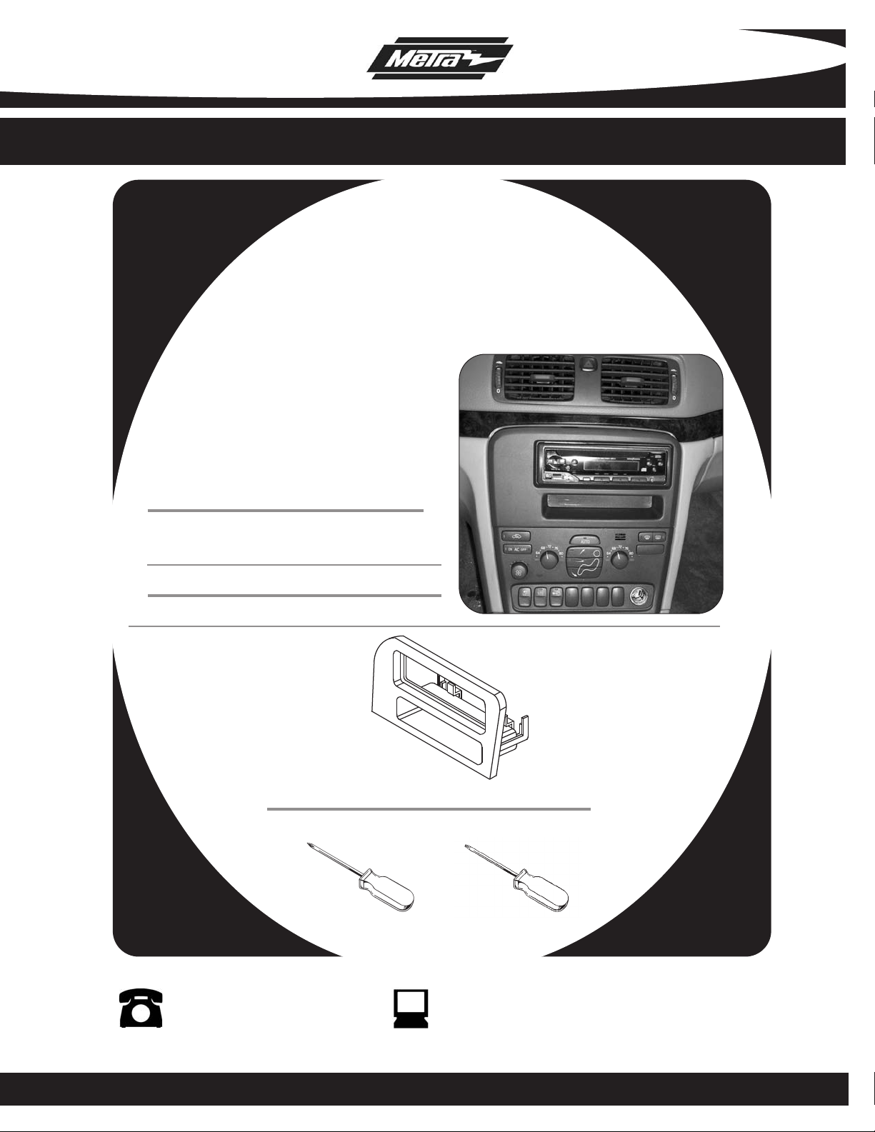
INSTALLATION INSTRUCTIONS FOR PART 99-9224
APPLICATIONS
1999-2006 Volvo S80
99-9224
KIT FEATURES
• DIN Head Unit Provision with Pocket
KIT COMPONENTS
( A) Radio Housing
A
TOOLS REQUIRED:
Phillips Screwdriver • T-25 Torx Driver
1-800-221-0932 www.metraonline.com
© COPYRIGHT 2004 METRA ELECTRONICS CORPORATION
Page 2

99-9224
TABLE OF CONTENTS
Dash Disassembly
1999-2006 Volvo S80 . . . . . . . . . . . . . . . . . . . . . . . . . . . . . . . . .1,2
Kit Assembly
DIN Head Unit Provision with Pocket . . . . . . . . . . . . . . . . . . . . . . 3
Final Assembly . . . . . . . . . . . . . . . . . . . . . . . . . . . . . . . . . . . . . . 4
Page 3
99-9224
12
VOLT
12
VOLT
AUTO
ON AC OFF
64
68
72
76
80
64
68
72
76
80
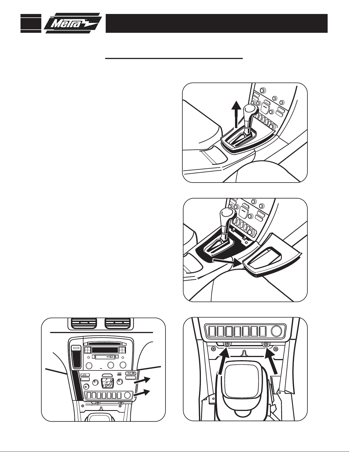
1999-2006 VOLVO S80
Disconnect the negative battery
1
terminal to prevent an accidental
short circuit.
2
Unsnap gear shifter trim panel.
(Figure A)
Unsnap gear shifter boot to separate
3
it from the gear shifter trim panel
and remove trim panel.
(Figure B)
DASH DISASSEMBLY
A
Remove (2) T-25 Torx head screws
4
from bottom of climate controls.
(Figure C)
Unsnap the climate controls from
5
bottom edge of the radio. Unplug
and remove the climate controls.
(Figure D)
D
B
C
1
Page 4

99-9224
TOP SNAP
TORX
HEAD
1999-2006 VOLVO S80
Remove (2) T-25 Torx head screws
6
from bottom of radio. Unplug and
remove the radio.
7
Depress the snaps on the top and
bottom of the pocket to remove it
from the radio bracket.
8
Remove (5) T-25 Torx head screws
securing the radio to the radio
bracket and slide the bracket off of
the radio.
Note: Save the radio bracket for
use with radio housing.
(See Figure G)
(Figure E)
(Figure F)
DASH DISASSEMBLY
E
F
(Figure H)
H
G
2
Page 5

99-9224
DIN HEAD UNIT PROVISION
NOTE: Also refer to the instructions
included with the aftermarket radio.
1
Using a Phillips screw driver remove
the rear support bracket from the
radio housing.
Snap the radio housing into the radio
2
bracket (removed from factory radio)
and replace rear support bracket.
(Figure B)
(Figure A)
KIT ASSEMBLY
A
B
Slide the DIN cage into the radio
3
housing and secure by bending the
metal locking tabs outward.
Slide the radio into the cage/ radio
4
housing assembly until it snaps into
place.
D
(Figure D)
(Figure C)
C
3
Page 6

99-9224
FINAL ASSEMBLY
FINAL ASSEMBLY
Locate the factory wiring harness in the dash and make the connection as shown.
1
Metra recomends using the proper mating adapter and making the connections as
shown. (Isolate and individually tape off the ends of any unused wires to prevent
electrical short circuit.)
Re-connect the negative battery terminal and test the unit for proper operation.
2
3
Reassemble radio and dash assemblies in reverse order of disassembly.
FINAL WIRING CONNECTIONS
Make wiring connections using the EIA color code chart shown below and the instructions included with the head
unit. Metra recommends making connections as shown below; Strip, Splice, Solder, Tape. Isolate and individually
tape off ends of any unused wires to prevent electrical short circuit.
A
B
C
D
A) Strip wire ends back 1/2"
B) Twist ends together
C) Solder
D) Tape
METRA / EIA WIRING CODE
12V Ignition / Acc . . . Red
12V Batt / Memory . . Yellow
Ground . . . . . . . . . . . Black*
Power Antenna . . . . . Blue
Amp Turn-On . . . . . . Blue / White
Amp Ground . . . . . . . Black / White
Illumination. . . . . . . . Orange
Right Front (+) . . . . . Gray
Right Front (-) . . . . . . Gray / Black
Left Front (+) . . . . . . White
Left Front (-) . . . . . . . White / Black
Right Rear (+). . . . . . Violet
Right Rear (-) . . . . . . Violet / Black
Left Rear (+). . . . . . . Green
Dimmer . . . . . . . . . . Orange / White
*NOTE: When Black a wire is not present, ground radio to vehicle chassis.
All colors may not be present on all leads due to manufacturer’s specifications.
Left Rear (-) . . . . . . . Green / Black
4
Page 7

99-9224
NOTES
5
Page 8

INST999224
1-800-221-0932 www.metraonline.com
REV. 03/15/06 © COPYRIGHT 2004 METRA ELECTRONICS CORPORATION INST99-9224
 Loading...