

Page 1
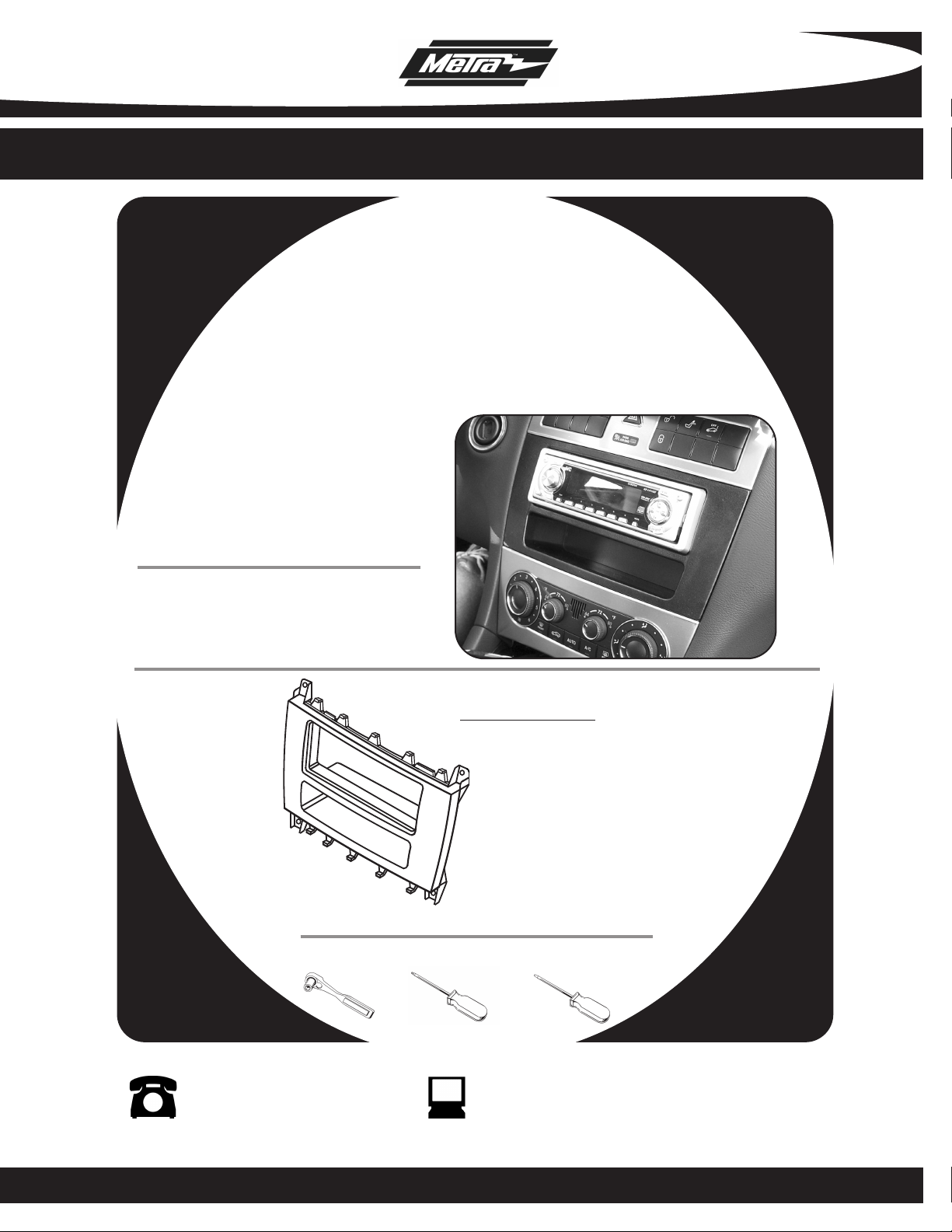
INSTALLATION INSTRUCTIONS FOR PART 99-8712
APPLICATIONS
Mercedes Benz C Class
2005-2007
99-8712
KIT FEATURES
• DIN head unit provision with pocket
KIT COMPONENTS
A) Radio Housing
Antenna Adapter:
• 40-VW12 - Mercedes antenna adapter
A
TOOLS REQUIRED:
Socket Wrench • Torx Screwdriver • Small Flat Blade Screwdriver
1-800-221-0932 www.metraonline.com
© COPYRIGHT 2004-2010 METRA ELECTRONICS CORPORATION REV. 10-07-10
Page 2

99-8712
KNOWLEDGE IS POWER
Enhance your installation and fabrication skills by
enrolling in the most recognized and respected
mobile electronics school in our industry.
Log onto www.installerinstitute.com or call
800-354-6782 for more information and take
steps toward a better tomorrow.
TABLE OF CONTENTS
Dash Disassembly . . . . . . . . . . . . . . . . . . . . . . . . . . . . . . . . . . 1-2
Kit Assembly . . . . . . . . . . . . . . . . . . . . . . . . . . . . . . . . . . . . . . . 3
Final Assembly . . . . . . . . . . . . . . . . . . . . . . . . . . . . . . . . . . . . . . 4
Page 3

99-8712
A
U
T
O
A
/
C
F
R
O
N
T
R
E
A
R
7
2
6
4
8
0
F
8
0
7
2
6
4
3
2
4
5
6
F
E
S
P
O
F
F
A
U
T
O
A
/
C
F
R
O
N
T
R
E
A
R
7
2
6
4
8
0
F
8
0
7
2
6
4
3
2
4
5
6
F
E
S
P
O
F
F
AU
T
O
A/
C
F
R
O
NT
REA
R
72
64
80
F
80
72
64
3
2
4
5
6
F
2005-2007 MERCEDES BENZ C CLASS
1
Disconnect the negative battery
terminal to prevent an accidental
short circuit.
2
Unclip and remove cover around
shift lever and cup holder.
3
Unclip and remove ashtray assembly.
(Figure B)
4
Remove (2) Torx screws from the
bottom of the climate control unit
then remove the unit.
(Figure A)
(Figure C)
DASH DISASSEMBLY
A
B
C
1
Page 4

99-8712
E
S
P
OF
F
2005-2007 MERCEDES BENZ C CLASS
5
Using a small screwdriver push the
release clips inside the vents inward
and rotate the vents upward to
expose the (2) Torx screws behind
the vents.
6
Unclip and remove the vent assembly.
(Figure E)
7
Remove (4) Torx screws securing
factory radio then remove the unit.
(Figure F)
(Figure D)
DASH DISASSEMBLY
D
E
F
2
Page 5

99-8712
DIN HEAD UNIT PROVISION
Slide the DIN cage into the Radio
1
Housing and secure by bending the
metal locking tabs down. (
Slide the aftermarket head unit into
2
the cage and secure. (
Figure B)
KIT ASSEMBLY
A
Figure A)
B
3
Page 6

99-8712
FINAL ASSEMBLY
FINAL ASSEMBLY
Locate the factory wiring harness in the dash and make the connection as shown.
1
Metra recomends using the proper mating adapter and making the connections as
shown. (Isolate and individually tape off the ends of any unused wires to prevent
Re-connect the negative battery terminal and test the unit for proper operation.
2
3
Reassemble radio and dash assemblies in reverse order of disassembly.
FINAL WIRING CONNECTIONS
Make wiring connections using the EIA color code chart shown below and the instructions included with the head
unit. Metra recommends making connections as shown below; Strip, Splice, Solder, Tape. Isolate and individually
tape off ends of any unused wires to prevent electrical short circuit.
A
B
C
D
METRA / EIA WIRING CODE
12V Ignition / Acc . . . Red
12V Batt / Memory . . Yellow
Ground . . . . . . . . . . . Black*
Power Antenna . . . . . Blue
Amp Turn-On . . . . . . Blue / White
A) Strip wire ends back 1/2"
B) Twist ends together
C) Solder
D) Tape
Right Front (+) . . . . . Gray
Right Front (-) . . . . . . Gray / Black
Left Front (+) . . . . . . White
Left Front (-) . . . . . . . White / Black
Right Rear (+). . . . . . Violet
Amp Ground . . . . . . . Black / White
Illumination. . . . . . . . Orange
Dimmer . . . . . . . . . . Orange / White
*NOTE: When Black a wire is not present, ground radio to vehicle chassis.
All colors may not be present on all leads due to manufacturer’s specifications.
Right Rear (-) . . . . . . Violet / Black
Left Rear (+) . . . . . . . Green
Left Rear (-) . . . . . . . Green / Black
4
Page 7

99-8712 INSTRUCTIONS
1-800-221-0932 www.metraonline.com
REV. 10/07/10
© COPYRIGHT 2004-2010 METRA ELECTRONICS CORPORATION
INST99-8712
 Loading...