

Page 1
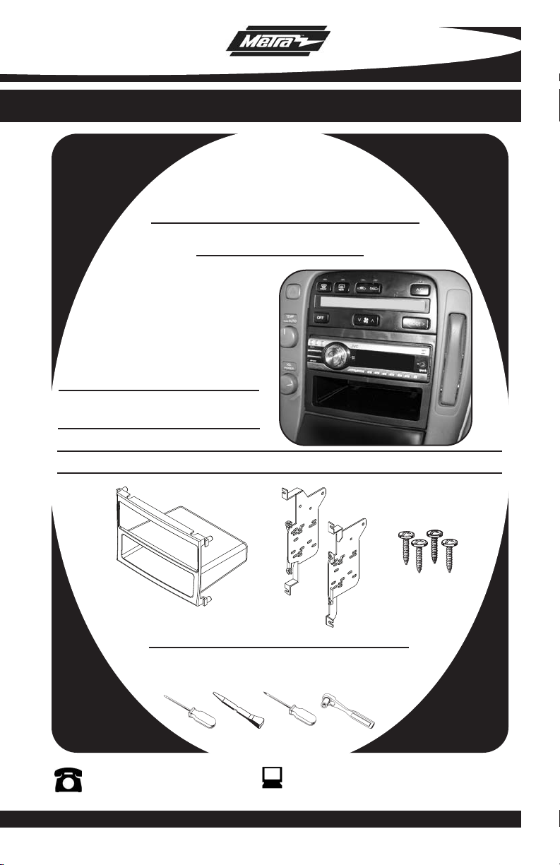
INSTALLATION INSTRUCTIONS FOR PART 99-8157B
APPLICATIONS
LEXUS SC SERIES
1992-2000
99-8157B
KIT FEATURES
• ISO Mount Radio Provision With Pocket
• Painted Black To Match Factory Dash
KIT COMPONENTS
A) Radio Housing With Pocket • B) Housing Brackets • C) (4) #8 X 3/8” Phillips Screws
A
TOOLS REQUIRED:
Small Flat Blade Screwdriver/ Panel Removal Tool
• Phillips Screwdriver • Socket Set
1-800-221-0932
© COPYRIGHT 2008 METRA ELECTRONICS CORPORA
B
www.metr
C
aonline.com
TION
Page 2
99-8157B
K
NOWLEDGE IS POWER
Enhance your installation and fabrication skills by
enrolling in the most recognized and respected
mobile electronics school in our industry.
Log onto www.installerinstitute.com or call
800-354-6782 for more information and take steps
toward a better tomorrow.
TABLE OF CONTENTS
Dash Disassembly
-
Lexus SC Series 1992-2000 . . . . . . . . . . . . . . . . . . . . . . . . . .
1,2
Kit Assembly
- ISO Mount Radio Provision with Pocket . . . . . . . . . . . . . . . . . . . . . . . . 3
Assembly . . . . . . . . . . . . . . . . . . . . . . . . . . . . . . . . . . . . . . . . . . .4
Final
*Note:
Refer also to the instructions included with the aftermarket radio.
Page 3
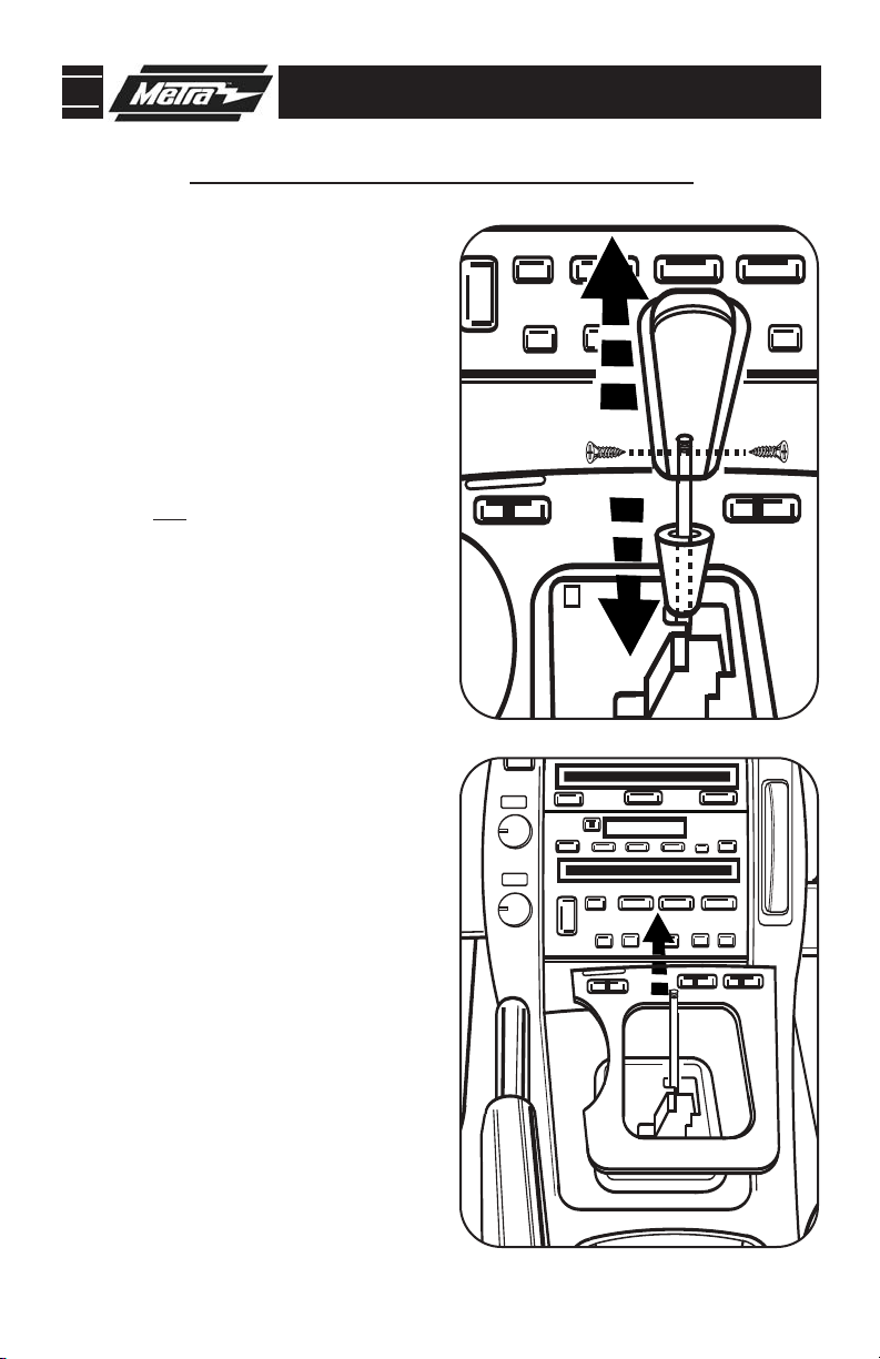
99-8157B DASH DISASSEMBLY
LEXUS SC SERIES 1992-2000
Disconnect the negative battery ter-
1
minal to prevent an accidental short
circuit.
Push down on collar around base of
2
shift knob then remove (2) Phillips
screws then pull up on knob to
remove. (
Unclip and remove the shifter trim
3
panel. Tip: Start at the front with
ashtray open.
Open cup holder lid then unclip and
4
remove the cup holder.
Continued on page 2.
Figure A)
(Figure B)
A
B
1
Page 4

99-8157B DASH DISASSEMBLY
LEXUS SC SERIES 1992-2000
Remove (6) Phillips screws securing
5
the upper console trim panel then
unclip and remove the panel. (
Remove (8) screws securing the radio
6
and climate control assembly.
Remove (4) screws securing the
7
climate controls to the bracket
assembly and remove the climate
controls. (Retain the screws and cli-
mate controls for reuse during kit
assembly) (
Continue to kit assembly.
Figure D)
Figure C)
C
2
D
Page 5

99-8157B KIT ASSEMBLY
LEXUS GS SERIES 1992-2000
ISO MOUNT RADIO PROVISON WITH POCKET
Note: Refer also to the instructions included with the aftermarket radio.
A
Attach the Housing Brackets to the
1
Radio Housing using the (4) #8 X3/8”
Phillips screws.
Position the factory climate controls
2
into the bracket/radio housing
assembly and secure using the
factory hardware.
Slide the aftermarket radio into the
3
bracket/radio housing assembly and
secure the radio to the assembly
using the screws supplied with the
(Figure C)
radio.
Continue to final assembly.
(Figure A)
(Figure B)
B
3
C
Page 6

99-8157B FINAL ASSEMBLY
FINAL ASSEMBLY
A
(A) Strip wire ends back 1/2"
B
B) Twist ends together
C) Solder
C
D
Locate the factory wiring harness in the dash. Metra recommends using the
1
proper mating adapter and making connections as shown. (Isolate and individually tape off the ends of any unused wires to prevent electrical short circuit.)
Re-connect the negative battery terminal and test the unit for proper operation.
2
Reassemble radio and dash assemblies in reverse order of disassembly.
3
D) Tape
FINAL WIRING CONNECTIONS
Make wiring connections using the EIA color code chart shown below and the instructions included with the
head unit. Metra recommends making connections as shown below; Strip, Splice, Solder, Tape. Isolate and
individually tape off ends of any unused wires to prevent electrical short circuit.
METRA / EIA WIRING CODE
12V Ignition / Acc . . . . . . . . . . Red
12V Batt / Memory. . . . . . . . . Yellow
Ground. . . . . . . . . . . . . . . . . . Black*
Power Antenna. . . . . . . . . . . . Blue
Amp Turn-On . . . . . . . . . . . . . Blue / White
Amp Ground. . . . . . . . . . . . . . Black / White
Illumination . . . . . . . . . . . . . . Orange
Dimmer . . . . . . . . . . . . . . . . . Orange / White
Right Front (+) . . . . . . . . . . . . Gray
Right Front (-). . . . . . . . . . . . . Gray/ Black
Left Front (+) . . . . . . . . . . . . . White
Left Front (-). . . . . . . . . . . . . . White / Black
Right Rear (+) . . . . . . . . . . . . Violet
Right Rear (-) . . . . . . . . . . . . . Violet / Black
Left Rear (+) . . . . . . . . . . . . . Green
Left Rear (-) . . . . . . . . . . . . . . Green / Black
*NOTE: When a Black wire is not present, ground radio to vehicle chassis.
All colors may not be present on all leads due to manufacturer’
Enjoy your newly installed radio!
s specifictions.
4
Page 7

99-8157B
NOTES
5
Page 8

99-8157B INSTRUCTIONS
1-800-221-0932
REV. 12/22/08 © COPYRIGHT 2008 METRA ELECTRONICS CORPORATION INST99-8157B
www.metraonline.com
 Loading...