

Page 1
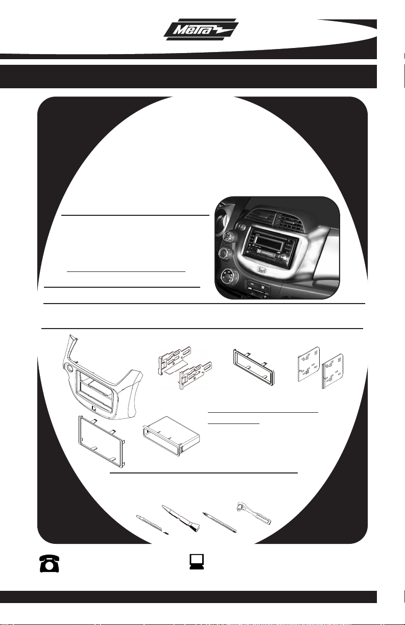
INSTALLATION INSTRUCTIONS FOR PART 99-7877S
APPLICATIONS
Honda Fit 2009-10
99-7877S
KIT FEATURES
• DIN Radio Provision with Pocket
• ISO Mount Radio Provision with Pocket
• Double DIN Radio Provision
• Stacked ISO Mount Units Provision
ainted To Match Factory Dash
• P
“S”= SILVER
KIT COMPONENTS
• A) Radio Housing • B) ISO Brackets • C) ISO Trim Plate • D) Double DIN Brackets
• E) Double DIN Trim Plate • F) Pocket
A
E
F
Small Flat Blade Screwdriver/ Panel Removal Tool
• Phillips Screwdriver • Socket Set
1-800-221-0932
© COPYRIGHT 2010 METRA ELECTRONICS CORPORATION
B
TOOLS REQUIRED:
C
WIRING AND ANTENNA CONNECTIONS
(Sold Separately)
• 70-1729 Honda Harness 2008-up
• 40-HD10 Honda Antenna Adapter 2005-up
D
www.metraonline.com
Page 2
99-7877S
K
NOWLEDGE IS POWER
Enhance your installation and fabrication skills by
enrolling in the most recognized and respected
mobile electronics school in our industry.
Log onto www.installerinstitute.com or call
800-354-6782 for more information and take steps
toward a better tomorrow.
TABLE OF CONTENTS
Dash Disassembly
-
Honda Fit 2009-10 .............................
. . . . . 1
Kit Assembly
- Kit Preparation . . . . . . . . . . . . . . . . . . . . . . . . . . . . . . . . . . . . . . . . . . 2
- DIN Radio Provision with Pocket . . . . . . . . . . . . . . . . . . . . . . . . . . . . .3
- ISO Mount Radio Provision with Pocket. . . . . . . . . . . . . . . . . . . . . . . . 4
- Double DIN Radio/ Stacked ISO Mount Units Provision . . . . . . . . . . . . . 5
*Note:
er also to the instructions included with the aftermarket radio.
Ref
Page 3

99-7877S DASH DISASSEMBLY
HONDA FIT 2009-10
Disconnect the negative battery
1
terminal to prevent an accidental
short circuit.
Unclip and remove the lower center
2
panel below radio. (
Remove (1) 8 MM bolt facing up
3
behind center panel.
Note: Slide the recirculation
control lever to FRESH for better
access to bolt. (
4
Open the upper glove box then use
a pry tool to unclip and remove the
radio/climate control assembly.
Figure B & C)
(
Remove (2) Phillips screws securing
5
the hazard switch to the back of the
factory radio panel. (
Remove (2) Phillips screws securing
6
the air bag light to the back of the
factory radio panel. (
7
Remove (5) Phillips screws securing
the a/c vents to the radio panel.
Figure A)
Figure A)
Figure D)
Figure E)
A
B
C
Remove (7) retaining clips from radio
8
housing to be used later in kit
preparation.
Continue to kit preparation.
E
D
1
Page 4

99-7877S KIT PREPARATION
KIT PREPARATION
Secure the hazard switch into the
1
radio housing panel using the factory
hardware. (
2
Secure the air bag light into the radio
housing panel using the factory
hardware. (
3
Secure the a/c vents to the radio
housing using the factory hardware.
(
Figure B)
Attach the (7) retaining clips to the
4
radio housing panel in the same
location as removed from the factory
radio panel.
Continue to kit assembly.
Figure A)
Figure A)
A
B
2
Page 5

99-7877S KIT ASSEMBLY
DIN MOUNT RADIO PROVISION WITH POCKET
*Note: Refer also to the instructions included with the aftermarket radio.
Locate the factory wiring harness in
1
the dash. Metra recommends using
the proper mating adapter from
Metra or AXXESS. Re-connect the
negative battery terminal and test
the unit for proper operation.
Slide the DIN cage into the Radio
2
Housing and secure by bending the
metal locking tabs down.
Slide the aftermarket head unit into
3
the cage and secure.
(Figure A)
(Figure B)
A
Snap the pocket into the Radio
4
Housing.
Re-assemble dash in reverse order of
5
disassembly.
(Figure C)
B
C
3
Page 6

99-7877S KIT ASSEMBLY
ISO MOUNT RADIO PROVISION WITH POCKET
*Note: Refer also to the instructions included with the aftermarket radio.
Locate the factory wiring harness in
1
the dash. Metra recommends using
the proper mating adapter from Metra
or AXXESS. Re-connect the negative
battery terminal and test the unit for
proper operation.
Mount the ISO Brackets to the head
2
unit with the screws supplied with
the unit.
Slide the head unit into the radio
3
opening until the side clips engage.
(Figure B)
Snap the Trim plate into the Radio
4
Housing.
5
Snap the Pocket into the radio
housing.
(Figure A)
(Figure B)
(Figure C)
A
B
Re-assemble dash in reverse order of
6
disassembly.
C
4
Page 7

99-7877S KIT ASSEMBLY
DOUBLE DIN RADIO PROVISION/
STACKED ISO MOUNT UNITS PROVISION
*Note: Refer also to the instructions included with the aftermarket radio.
Locate the factory wiring harness in
1
the dash. Metra recommends using
the proper mating adapter from Metra
or AXXESS. Re-connect the negative
battery terminal and test the unit for
proper operation.
2
Cut and remove the center bar from
the radio housing.
3
Snap the Double DIN brackets to the
inside edge of the Radio Housing.
(Figure B)
4
Slide the Double DIN head unit or
stacked ISO head units into the
bracket/radio housing assembly and
secure the Double DIN head unit or
stacked ISO head units to the
assembly using the screws supplied
with the radio.
(Figure A)
(Figure C)
A
B
Snap the Double DIN trim plate onto
5
the front of the radio/housing
assembly.
Re-assemble dash in reverse order of
6
disassembly.
(Figure C)
C
5
Page 8

99-7877S INSTRUCTIONS
1-800-221-0932
REV. 4/22/10 © COPYRIGHT 2010 METRA ELECTRONICS CORPORATION INST99-7877
www.metraonline.com
 Loading...