

Page 1
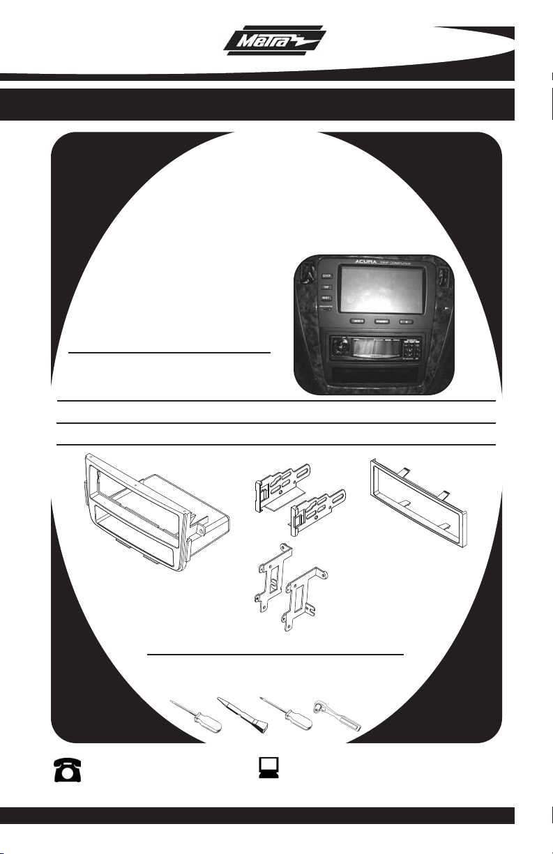
INSTALLATION INSTRUCTIONS FOR PART 99-7866
APPLICATIONS
ACURA MDX 2001-2006
99-7866
KIT FEATURES
• DIN Mount Radio Provision with Pocket
• ISO Mount Radio Provision with Pocket
KIT COMPONENTS
A) Radio Housing • B) ISO Brackets • C) ISO Trim Plate • D) Bracket Supports For Display
B
A
D
TOOLS REQUIRED:
Small Flat Blade Screwdriver/ Panel Removal Tool
• Phillips Screwdriver • Socket Set
1-800-221-0932
© COPYRIGHT 2003-2008 METRA ELECTRONICS CORPORA
www.metr
C
aonline.com
TION
Page 2
99-7866
K
NOWLEDGE IS POWER
Enhance your installation and fabrication skills by
enrolling in the most recognized and respected
mobile electronics school in our industry.
Log onto www.installerinstitute.com or call
800-354-6782 for more information and take
steps toward a better tomorrow.
TABLE OF CONTENTS
Dash Disassembly
-
ACURA MDX 2001-2006.........................
. . . . . . 1
Kit Preparation
- Display Unit Assembly . . . . . . . . . . . . . . . . . . . . . . . . . . . . . . . . . . . . 2
Assembly
Kit
- DIN Mount Radio Provision with Pocket . . . . . . . . . . . . . . . . . . . . . . . . 3
- ISO Mount Radio Provision with Pocket. . . . . . . . . . . . . . . . . . . . . . . . 4
Assembly . . . . . . . . . . . . . . . . . . . . . . . . . . . . . . . . . . . . . . . . . . . 5
Final
*Note:
Refer also to the instructions included with the aftermarket radio.
Page 3
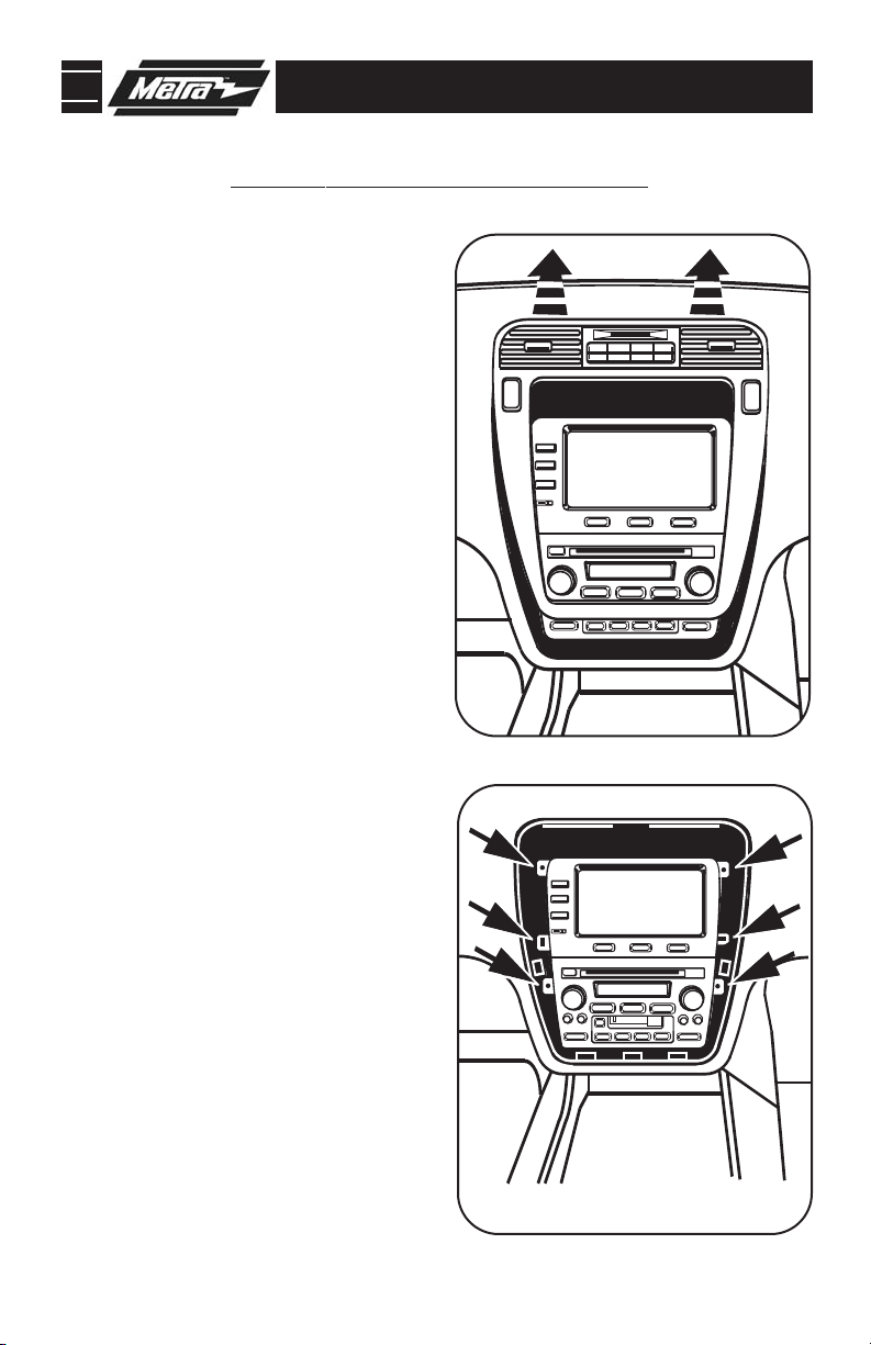
99-7866 DASH DISASSEMBLY
ACURA MDX 2001-2006
Disconnect the negative battery ter-
1
minal to prevent an accidental short
circuit.
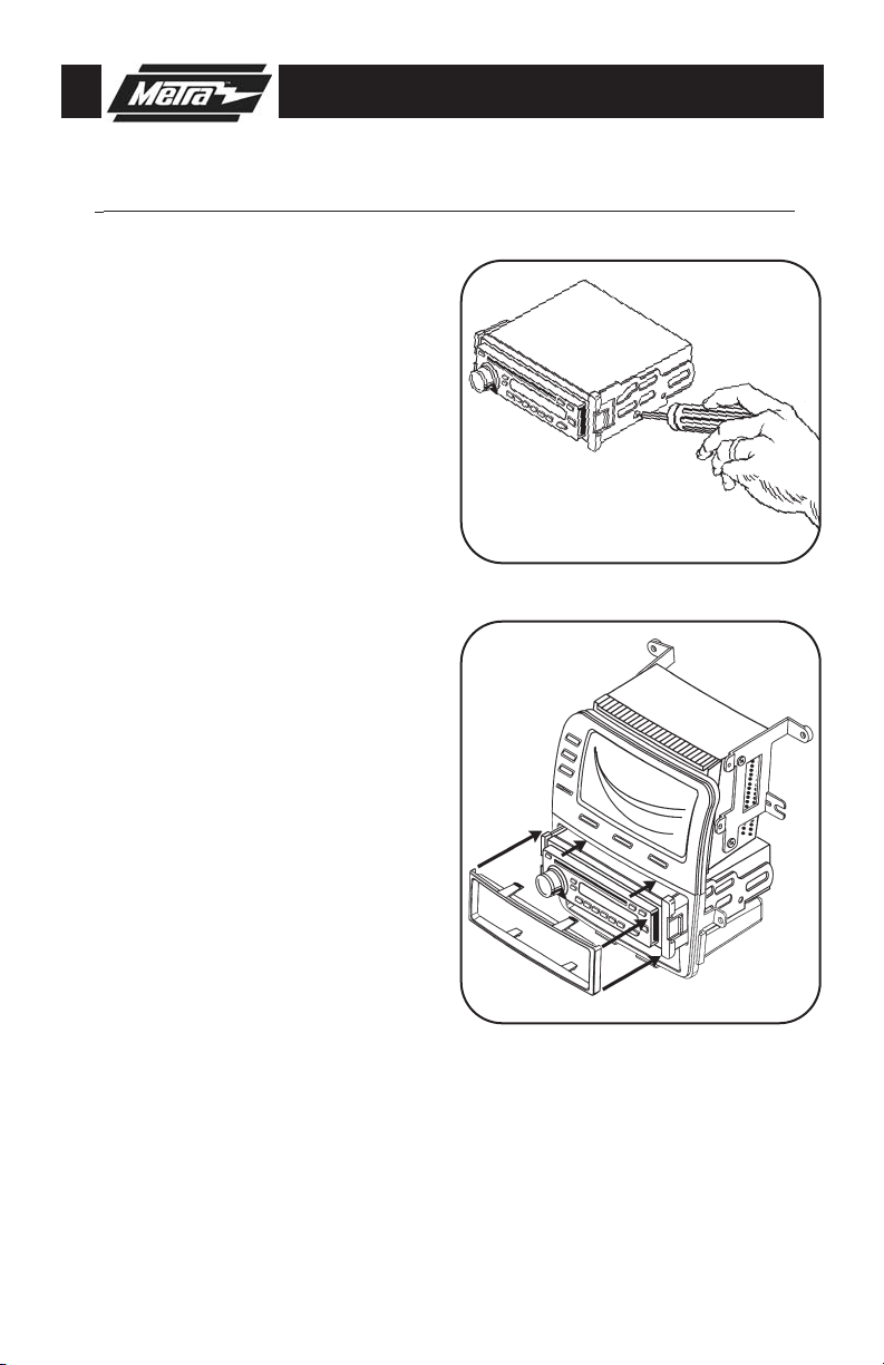
Unclip and remove trim panel around
2
radio/display including a/c vents..
(
Figure A)
Remove (6) mounting screws and
3
remove the audio/display unit from
the dash. (
Remove (8) screws from the audio
4
unit and (6) screws from the display
unit and remove the brackets from
the audio/display assembly.
Continue to kit preparation.
Figure B)
A
B
1
Page 4

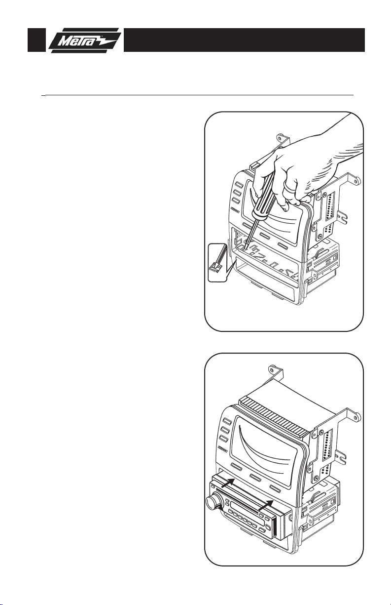
99-7866 KIT PREPARATION
DISPLAY UNIT ASSEMBLY
*Note: Refer also to the instructions included with the aftermarket radio.
A
Using the mounting screws from the
1
display unit, attach the brackets
supplied with the kit by aligning the
guide pins on the display with the
holes on the bracket.
Align guide pins on bottom of display
2
unit with holes on top of housing and
attach the unit to the housing using
the (2) screws previously removed.
(Figure B)
Continue to kit assembly.
(Figure A)
2
B
Page 5
99-7866 KIT ASSEMBLY
DIN MOUNT RADIO PROVISION WITH POCKET
*Note: Refer also to the instructions included with the aftermarket radio.
A
1
Slide the DIN cage into the radio housing and secure by bending the metal
locking tabs outward.
2
Slide the aftermarket radio into the DIN
cage until it snaps into place.
Continue to final assembly.
(Figure A)
(Figure B)
3
B
Page 6
99-7866 KIT ASSEMBLY
ISO MOUNT RADIO PROVISION WITH POCKET
*Note: Refer also to the instructions included with the aftermarket radio.
Mount the ISO Brackets to the radio
1
using the screws supplied with the
radio.
(Figure A)
Slide the radio into the radio opening
2
until it snaps into place.
Snap the ISO Trim Plate onto the front
3
of the Radio Housing.
Continue to final assembly.
(Figure B)
(Figure B)
A
B
4
Page 7
99-7866 FINAL ASSEMBLY
FINAL ASSEMBLY
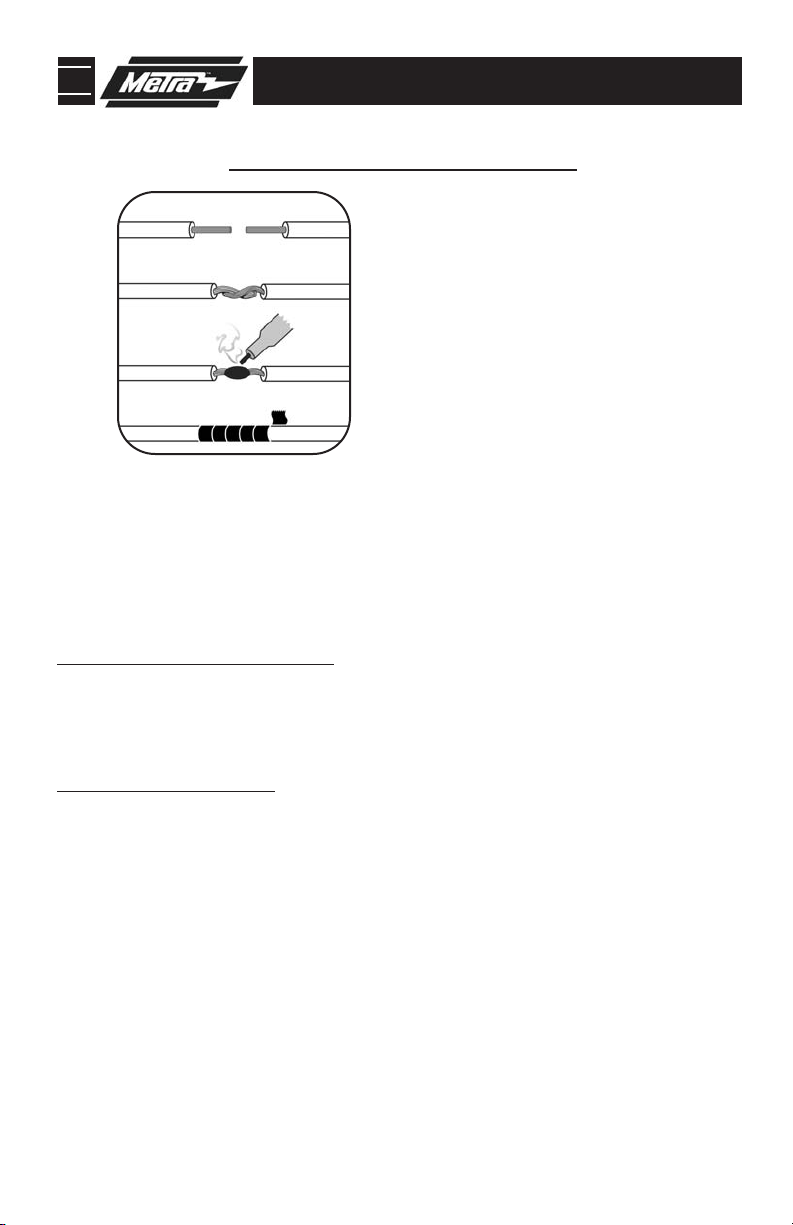
A
(A) Strip wire ends back 1/2"
B
B) Twist ends together
C) Solder
C
D
Locate the factory wiring harness in the dash. Metra recommends using the
1
proper mating adapter and making connections as shown. (Isolate and individually tape off the ends of any unused wires to prevent electrical short circuit.)
2
Re-connect the negative battery terminal and test the unit for proper operation.
Reassemble radio and dash assemblies in reverse order of disassembly.
3
D) Tape
FINAL WIRING CONNECTIONS
Make wiring connections using the EIA color code chart shown below and the instructions included with the
head unit. Metra recommends making connections as shown below; Strip, Splice, Solder, Tape. Isolate and
individually tape off ends of any unused wires to prevent electrical short circuit.
METRA / EIA WIRING CODE
12V Ignition / Acc . . . . . . . . . . Red
12V Batt / Memory. . . . . . . . . Yellow
Ground. . . . . . . . . . . . . . . . . . Black*
Power Antenna. . . . . . . . . . . . Blue
Amp Turn-On . . . . . . . . . . . . . Blue / White
Amp Ground. . . . . . . . . . . . . . Black / White
Illumination . . . . . . . . . . . . . . Orange
Dimmer . . . . . . . . . . . . . . . . . Orange /
White
Right Front (+) . . . . . . . . . . . . Gray
Right Front (-). . . . . . . . . . . . . Gray/ Black
Left Front (+) . . . . . . . . . . . . . White
Left Front (-). . . . . . . . . . . . . . White / Black
Right Rear (+) . . . . . . . . . . . . Violet
Right Rear (-) . . . . . . . . . . . . . Violet / Black
Left Rear (+) . . . . . . . . . . . . . Green
Left Rear (-)
. . . . . . . . . . . . . .
Green / Black
*NOTE: When a Black wire is not present,
All colors may not be present on all leads due to manufacturer’s specifictions.
Enjoy your newly installed radio!
ground radio to vehicle chassis.
5
Page 8

99-7866 INSTRUCTIONS
1-800-221-0932
REV. 12/29/08 © COPYRIGHT 2003-2008 METRA ELECTRONICS CORPORATION INST99-7866
www.metraonline.com
 Loading...