

Page 1
KIT FEATURES
Shaft and
DIN unit
provisions
99-7579
Equalizer
provisions
Various
mounting depth
alternatives
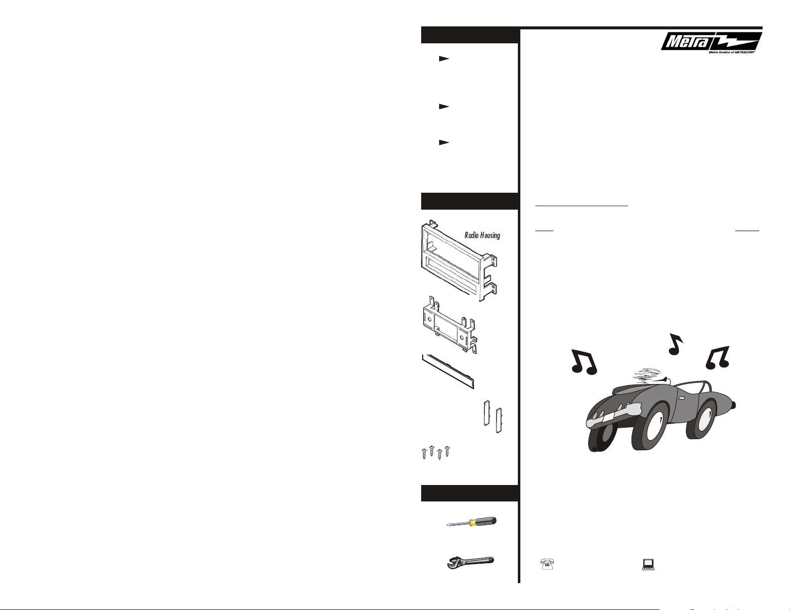
KIT COMPONENTS
Radio Housing
Faceplate
Equalizer
Dummy Plate
INSTALLATION
INSTRUCTIONS
APPLICATIONS
CAR PAGE
NISSAN
Pathfinder 1996-00.................................................1-2
Rev.130103
Snap Spacers
(4) #8 x 1" Phillips
Pan-head Screws
TOOLS REQUIRED
Phillips screwdriver
Adjustable wrench
1-800-221-0932 www.metraonline.com
© COPYRIGHT 2001 METRA ELECTRONICS CORPORATION
Page 2
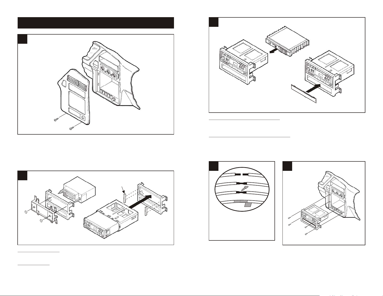
ALL VEHICLES
1
Disconnect the negative battery terminal to prevent an accidental short circuit. Remove (2)
screws from the base of the radio trim bezel. Unclip the bottom edge of the radio trim bezel and
disconnect the hazard light, defroster, wiper and cligarette lighter wiring. Remove the radio
trim bezel. Remove (4) screws securing the factory head unit and disconnect the wiring.
3
Fig. A
Fig. B
IF AN EQUALIZER WILL BE INCLUDED: Slide the aftermarket equalizer into the back of the
Radio Housing. Using the hardware included with the equalizer, mount the unit to the kit.
(see Fig. A)
IF AN EQUALIZER WILL NOT BE INCLUDED: Snap the Equalizer Dummy Plate into the
Radio Housing. (see Fig. B)
2
*OPTIONAL
Fig. A
Fig. B
2-SHAFT HEAD UNITS: Attach the Faceplate to the Radio Housing. Slide the aftermarket
head unit into the kit and secure with shaft nuts. (see Fig. A)
DIN HEAD UNITS: Attach the Snap Spacers* to the inner walls of the Radio Housing. Slide
the DIN cage into the kit and secure by bending the metal locking tabs down. Slide the
aftermarket head unit into the cage until secure. (see Fig. B)
1
4
A
B
C
D
A) Strip wire ends back ½"
B) Twist ends together
C) Solder
D) Tape
Locate the factory wiring harness in the
dash. Metra recommends using the
proper mating adaptor and making
connections as shown. (Isolate and
individually tape off the ends of any
unused wires to prevent electrical short
circuit).
5
Re-connect the battery terminal and test the unit
for proper operation. Mount the head unit/kit
assembly to the sub-dash with (4) screws
previously removed in step #1.
2
 Loading...