

Page 1
INSTALLATION INSTRUCTIONS FOR PART 99-7519B
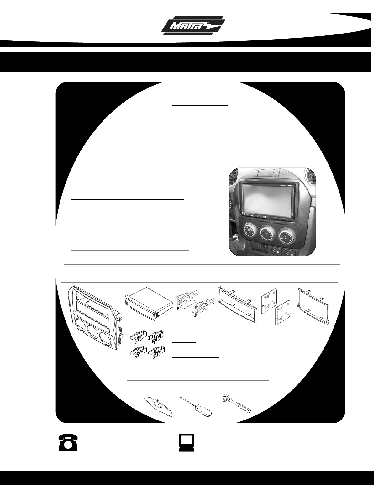
APPLICATIONS
Mazda MX-5 Miata
2009-2010
99-7519B
KIT FEATURES
• DIN Head Unit Provision with pocket
• ISO DIN Head Unit Provision with pocket
• Double DIN Head Unit Provision
• Stacked ISO DIN Head Unit Provision
• Painted Matte Black to Match Factory
KIT COMPONENTS
A) Radio Housing • B) Snap-In Pocket • C) ISO Brackets • D) ISO Trim Plate • E) Double DIN Brackets
• F) Double DIN Trim Plate • G) (4) Panel Clips
D
E
F
A
B
F
Cutting Tool • Phillips Screwdriver • Socket Wrench
C
WIRING AND ANTENNA CONNECTIONS (Sold Separately)
Harness:
• 70-7903 - Mazda harness 2001-up
Antenna Adapter:
• Not required
TOOLS REQUIRED:
1-800-221-0932 www.metraonline.com
© COPYRIGHT 2004-2010 METRA ELECTRONICS CORPORATION
Page 2
99-7519B
KNOWLEDGE IS POWER
Enhance your installation and fabrication skills
by enrolling in the most recognized and respected
mobile electronics school in our industry.
Log onto www.installerinstitute.com
or call 800-354-6782 for more information
and take steps toward a better tomorrow.
TABLE OF CONTENTS
Dash Disassembly ....................................................................... 1-3
Kit Preparation
............................................................................... 4
Kit Assembly:
DIN Head Unit Provision.................................................................. 5
ISO DIN Head Unit Provision........................................................... 6
Double DIN Head Unit Provision..................................................... 7
Stacked ISO DIN Head Unit Provision............................................ 8
Final Assembly ..
............................................................................ 9
CAUTION : Metra recommends disconnecting the
negative battery terminal before beginning any
installation. All accessories, switches and especially
air bag indicator lights must be plugged in before
reconnecting the battery or cycling the ignition.
Metra reccommends MECP
certified technicians
Page 3
99-7519B
MAZDA MX-5 MIATA 2009-2010
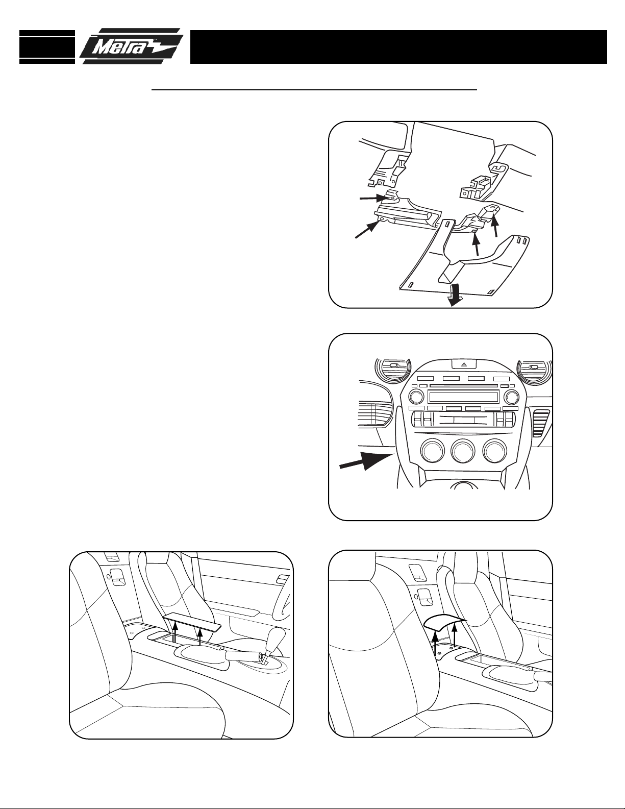
1
Unclip panel below steering column
and remove. (Figure A)
2
Remove (4) Phillips screws from
metal brace below steering column
and remove. (Figure A)
3
Looking at the side of the radio/climate control panel from underneath
the steering column opening, remove
(1) 10mm bolt from the side of the
radio chassis. (Figure B)
DASH DISASSEMBLY
A
B
4
With the center console lid closed
unclip and remove the cover on the
back side of the center console and
remove the (2) Phillips screws
revealed. (Figure C)
5
Remove the rubber mat inside of the
cup holder then remove the (1)
Phillips screw revealed. (Figure D)
D
C
1
Page 4
99-7519B
MAZDA MX-5 MIATA 2009-2010
6
Unclip, unplug and remove the entire
center console. (Figure E)
DASH DISASSEMBLY
E
F
7
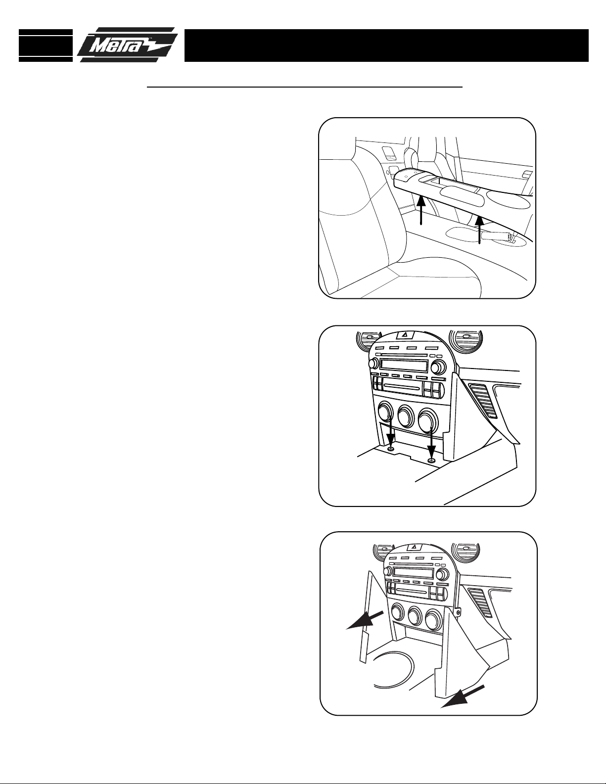
Remove the (2) Phillips screws
securing the side panels from each
side of the radio/climate control
panel. (Figure F)
8
Carefully remove the side panels
from each side of the radio/climate
control panel by pulling straight back
towards the rear of the car.
(Figure G)
G
2
Page 5

99-7519B
MAZDA MX-5 MIATA 2009-2010
9
Remove (2) Phillips screws, (1) on
each side, from the side of the
radio/climate control panel.
(Figure H)
DASH DISASSEMBLY
H
I
10
Pull radio/climate control panel out,
disconnect plugs and remove.
(Figure I)
11
Turn the radio/climate control panel
over and remove the (4) screws that
hold the climate control to the bezel,
then remove the climate control.
(Figure J)
J
3
Page 6

99-7519B
MAZDA MX-5 MIATA 2009-2010
1
Attach the (4) Panel Clips to the posts
on the back of the radio housing.
(Figure A)
KIT PREPARATION
A
4
Page 7

99-7519B
DIN HEAD UNIT PROVISION
1
Turn over the 99-7519B housing,
take the climate control and screws
removed from the factory panel and
attach the climate control to the kit
housing using the factory screws.
(Figure A)
2
Slide the pocket into the bottom
section of the kit housing.
KIT ASSEMBLY
A
B
(Figure B)
3
Slide the DIN cage into the Radio
Housing and secure by bending the
metal locking tabs down.
4
Slide the aftermarket head unit into
the cage and secure.
(Figure C)
(Figure D)
C
D
5
Page 8

99-7519B
ISO DIN HEAD UNIT PROVISION
1
Turn over the 99-7519B housing,
take the climate control and screws
removed from the factory panel and
attach the climate control to the kit
housing using the factory screws.
(Figure A)
2
Slide the pocket into the bottom
section of the kit housing.
KIT ASSEMBLY
A
B
(Figure B)
3
Mount the ISO Brackets to the head
unit with the screws supplied with
the unit.
4
Slide the head unit into the radio
opening until the side clips engage.
(Figure D)
5
Snap the Trim plate into the Radio
Housing.
(Figure C)
(Figure D )
C
D
6
Page 9

99-7519B
DOUBLE DIN HEAD UNIT PROVISION
1
Turn over the 99-7519B housing,
take the climate control and screws
removed from the factory panel and
attach the climate control to the kit
housing using the factory screws.
(Figure A)
2
Cut the rib in the middle of the 997519B housing to make room for the
DDIN brackets.
(Figure A)
KIT ASSEMBLY
A
B
3
Slide the appropriate DDIN bracket
into the kit housing.
4
Slide the DDIN radio unit into DDIN
brackets and secure the unit to the
kit using the screws supplied with
the head unit.
5
Snap the DDIN trim plate into the
front of the kit housing.
(Figure C)
(Figure B)
(Figure C )
C
7
Page 10

99-7519B
STACKED ISO DIN HEAD UNIT PROVISION
1
Turn over the 99-7519B housing,
take the climate control and screws
removed from the factory panel and
attach the climate control to the kit
housing using the factory screws.
(Figure A)
2
Cut the rib in the middle of the 997519B housing to make room for the
DDIN brackets.
(Figure A)
KIT ASSEMBLY
A
B
3
Slide the appropriate DDIN bracket
into the kit housing.
4
Slide the stacked ISO DIN units into
the DDIN bracket assembly and
secure the units to the kit using the
screws supplied with the head units.
(Figure C)
5
Snap the DDIN trim plate into the
front of the kit housing.
(Figure B)
(Figure C )
C
8
Page 11

99-7519B
FINAL ASSEMBLY
FINAL ASSEMBLY
Locate the factory wiring harness in the dash and make the connection as shown.
1
Metra recomends using the proper mating adapter and making the connections as
shown. (Isolate and individually tape off the ends of any unused wires to prevent
Re-connect the negative battery terminal and test the unit for proper operation.
2
3
Reassemble radio and dash assemblies in reverse order of disassembly.
FINAL WIRING CONNECTIONS
Make wiring connections using the EIA color code chart shown below and the instructions included with the head
unit. Metra recommends making connections as shown below; Strip, Splice, Solder, Tape. Isolate and individually
tape off ends of any unused wires to prevent electrical short circuit.
A
B
C
D
A) Strip wire ends back 1/2"
B) Twist ends together
C) Solder
D) Tape
METRA / EIA WIRING CODE
12V Ignition / Acc . . . Red
12V Batt / Memory . . Yellow
Ground . . . . . . . . . . . Black*
Power Antenna . . . . . Blue
Amp Turn-On . . . . . . Blue / White
Right Front (+) . . . . . Gray
Right Front (-) . . . . . . Gray / Black
Left Front (+) . . . . . . White
Left Front (-) . . . . . . . White / Black
Right Rear (+). . . . . . Violet
Amp Ground . . . . . . . Black / White
Illumination. . . . . . . . Orange
Dimmer . . . . . . . . . . Orange / White
*NOTE: When Black a wire is not present, ground radio to vehicle chassis.
All colors may not be present on all leads due to manufacturer’s specifications.
Right Rear (-) . . . . . . Violet / Black
Left Rear (+). . . . . . . Green
Left Rear (-) . . . . . . . Green / Black
9
Page 12

99-7519B INSTRUCTIONS
1-800-221-0932 www.metraonline.com
REV. 09/29/10
© COPYRIGHT 2004-2010 METRA ELECTRONICS CORPORATION INST99-7519B
 Loading...