

Page 1
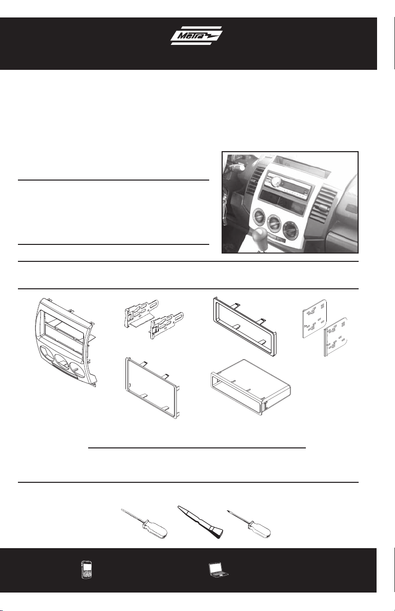
INSTALLATION INSTRUCTIONS FOR PART 99-7509
APPLICATIONS
Mazda 5 2006-up
(with manual climate controls)
99-7509
KIT FEATURES
• Painted to match factory dash
• DIN radio provision with pocket
• ISO radio provision with pocket
• Double DIN radio provision
• Stacked ISO mount units provision
KIT COMPONENTS
• A) Radio Housing • B) ISO Brackets • C) ISO Trim Plate • D) Double DIN Brackets
• C) Double DIN Trim Plate • D) Snap In Pocket
A
B
C
D
E
F
WIRING & ANTENNA CONNECTIONS (Sold Separately)
Wiring Harness: •70-7903 - Mazda Harness 01-up
TOOLS REQUIRED
Small Flat Blade Screwdriver • Panel Removal Tool • Phillips Screwdriver
METRA. THE WORLD’S BEST KITS.™
1-800-221-0932
© COPYRIGHT 2004-2011 METRA ELECTRONICS CORPORATION
metraonline.com
Page 2
99-7509
Table of Contents
Dash Disassembly
– 2006-up Mazda 5 3-5
Kit Assembly
– DIN radio provision with pocket 6
– ISO mount radio provision with pocket 7-8
– Double DIN/stacked ISO DIN head unit provision 9
Caution
Metra recommends disconnecting the negative battery terminal before beginning any
installation. All accessories, switches, and especially air bag indicator lights must be
plugged in before reconnecting the battery or cycling the ignition.
*NOTE: Refer also to the instructions included with the aftermarket radio.
KNOWLEDGE IS POWER
Enhance your installation and fabrication skills by
enrolling in the most recognized and respected
mobile electronics school in our industry.
Log onto www.installerinstitute.com or call
800-354-6782 for more information and take steps
toward a better tomorrow.
Metra recommends MECP
certified technicians
Page 3
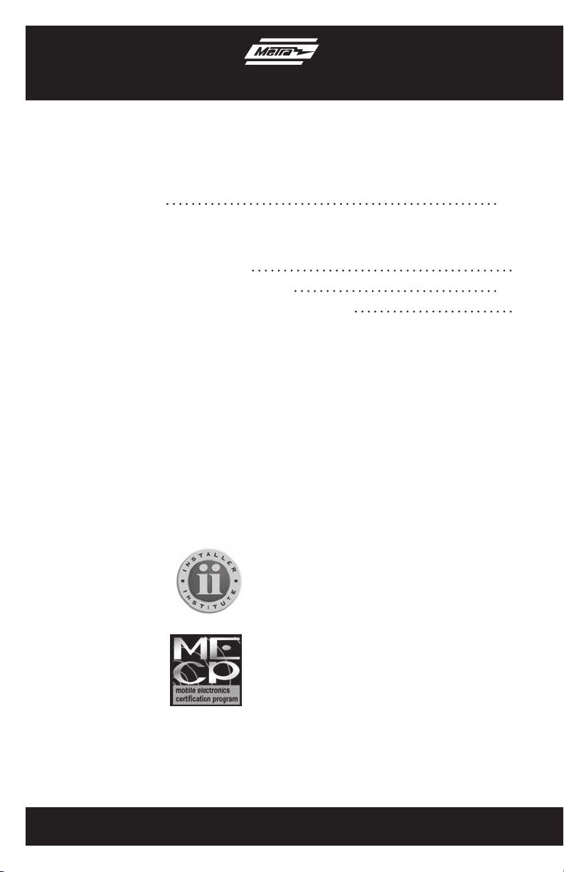
Dash Disassembly
1. Remove the shifter. (Figure A)
2. Remove (2) Phillips screws exposed
below shift lever trim panel. (Figure B)
Continued on next page
99-7509
(Figure A)
A/C
P
R
N
M-D
A/C
3
(Figure B)
Page 4
99-7509
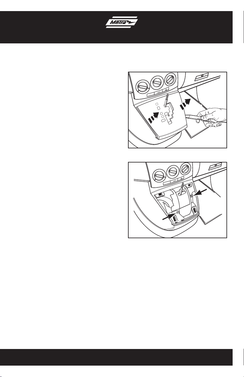
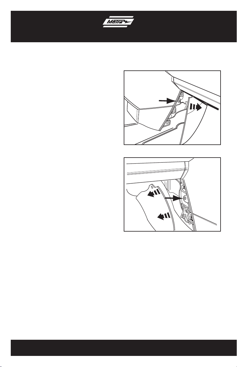
Dash Disassembly
3. Unclip and remove the center console
side trim panels then remove (1) Phillips
screw per side behind panels.
(Figure C,D).
Continue to next page
(Figure C)
4
(Figure D)
Page 5

Dash Disassembly
4. Unclip and pull the center console
towards the rear of the vehicle.
Note: You do not have to remove the
center console completely. (Figure E)
5. Remove (2) Phillips screws at the
bottom of the radio trim panel then
unclip the panel including the factory
radio. Unplug and remove the panel.
Note: The climate controls do not
come out with the panel.
(Figure F,G)
Continue to kit assembly
99-7509
(Figure E)
A/C
5
(Figure F)
A/C
(Figure G)
Page 6

Kit Assembly 99-7509
DIN radio provision with pocket
1. Locate the factory wiring harness in the
dash. Metra recommends using the
proper mating adapter from Metra or
AXXESS. Re-connect the negative
battery terminal and test the unit for
proper operation.
2. Slide the DIN cage into the radio
housing and secure by bending the
metal locking tabs outward. (Figure A)
3. Slide the aftermarket radio into the cage
until it snaps into place. (Figure B)
4. Snap the pocket into the radio housing.
(Figure C)
5. Reassemble dash in reverse order
of disassembly.
(Figure A)
6
(Figure B)
(Figure C)
Page 7

Kit Assembly 99-7509
ISO mount radio provision with pocket
1. Locate the factory wiring harness in the
dash. Metra recommends using the
proper mating adapter from Metra or
AXXESS. Re-connect the negative
battery terminal and test the unit for
proper operation.
2. Mount the ISO brackets to the
aftermarket radio using the screws
supplied with the radio. (Figure A)
3. Slide the radio into the radio housing
until it snaps into place. (Figure B)
4. Snap the trim plate onto the front of the
radio housing. (Figure C)
5. Snap the pocket into the Radio.
Countinue to next page
(Figure A)
7
(Figure B)
(Figure C)
Page 8

Kit Assembly 99-7509
ISO mount radio provision with pocket
6. Snap the pocket into the radio housing.
(Figure D)
7. Reassemble dash in reverse order
of disassembly.
(Figure D)
8
Page 9

Kit Assembly 99-7509
Double DIN/Stacked ISO units provision
1. Locate the factory wiring harness in the
dash. Metra recommends using the
proper mating adapter from Metra or
AXXESS. Re-connect the negative
battery terminal and test the unit for
proper operation.
2. Cut and remove the center bar from the
radio housing. (Figure A)
3. Snap the double DIN brackets to the
inside edge of the radio housing.
(Figure B)
4. Slide the double DIN or stacked ISO
unit(s) into the bracket/radio housing
assembly and secure the double DIN
or stacked ISO unit(s) to the assembly
using the screws supplied with the
unit(s). (Figure C)
5. Snap the double DIN trim plate onto the
front of the Radio Housing.
(Figure C)
6. Reassemble dash in reverse order
of disassembly.
(Figure A)
(Figure B)
9
(Figure C)
Page 10

Notes
Page 11

Notes
Page 12

INSTALLATION INSTRUCTIONS FOR PART 99-7509
REV. 5/26/11
METRA. THE WORLD’S BEST KITS.™
1-800-221-0932
© COPYRIGHT 2004-2011 METRA ELECTRONICS CORPORATION
metraonline.com
 Loading...