

Page 1
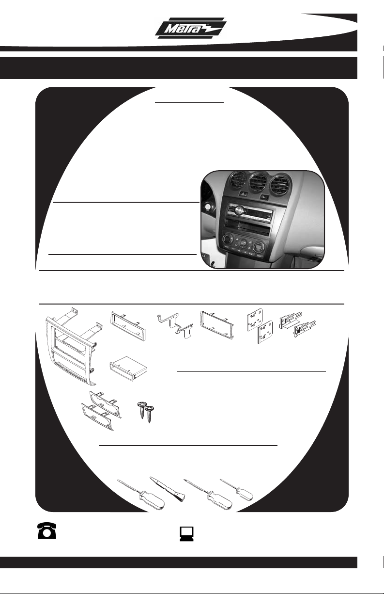
INSTALLATION INSTRUCTIONS FOR PART 99-7423
APPLICATIONS
NISSAN Altima
2007-2011
99-7423
KIT FEATURES
• DIN Radio Provision with Pocket
• ISO Mount Radio Provision with Pocket
• Double DIN Radio Provision
• Stacked ISO Mount Units Provision
KIT COMPONENTS
• A) Radio Housing • B) Radio Housing Trim Plate • C) Radio Housing Brackets
• D) Double DIN Trim Plate • E) Double DIN Brackets • F) ISO Brackets • G) Pocket
• H) (2) Climate Control Trim Panels • I) (2) #8 3/8” Screws
B
A
G
H I
TOOLS REQUIRED:
Flat Blade Screwdriver/ Panel Removal Tool
• Phillips Screwdriver • Torx Screwdriver
1-800-221-0932
© COPYRIGHT 2007-2010 METRA ELECTRONICS CORPORATION
C
D
Harness & Antenna Connections (sold separately)
• 70-7552 - Nissan Harness 07-up
• 40-NI12 - Nissan Antenna Adapter 07-up
E
F
www.metraonline.com
Page 2
99-7423
TABLE OF CONTENTS
Dash Disassembly
- NISSAN Altima 2007 -2011 . . . . . . . . . . . . . . . . . . . . . . . . . . . . . . . . . . . . . . . . . 1
Kit Preparation
. . . . . . . . . . . . . . . . . . . . . . . . . . . . . . . . . . . . . . . . . . . . . . . . . . . 2
Kit Assembly
- DIN Radio Provision with Pocket . . . . . . . . . . . . . . . . . . . . . . . . . . . . . . . . . . 3
- ISO Mount Radio Provision with Pocket . . . . . . . . . . .. . . . . . . . . . . . . . . . . . 4
- Double DIN Radio Provision . . . . .. . . . . . . . . . . . . . . . . . . . . . . . . . . . . . . . . . 5
- Stacked ISO Units Provision . . . . . . . . . . . . . . . . . . . . . . . . . . . . . . . . . . . . . . 6
F
inal Assembly
*Note:
Refer also to the instructions included with the aftermarket radio.
. . . . . . . . . . . . . . . . . . . . . . . . . . . . . . . . . . . . . . . . . . 7
KNOWLEDGE IS POWER
Enhance your installation and fabrication skills by
enrolling in the most recognized and respected
mobile electronics school in our industry.
Log onto www.installerinstitute.com or call
800-354-6782 for more information and take steps
toward a better tomorrow.
Page 3
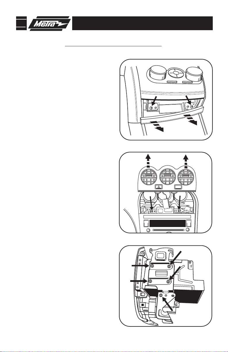
99-7423 DASH DISASSEMBLY
PASS
AIR BAG
NISSAN ALTIMA 2007-2011
1
Disconnect the negative battery ter-
minal to prevent an accidental short
circuit.
2
Unclip and remove trim panel
between the shifter and the radio/ climate control panel.
3
Remove (2) Phillips screws exposed
behind panel below radio/climate
control panel.
4
Unclip and remove the climate control
vent trim panel then remove (2)
Phillips screws exposed behind panel.
(Figure B)
5
Unclip, unplug and remove entire
radio/climate control panel.
(Figure A)
(Figure A)
(Figure B)
A
B
6
Remove (5) T-20 Torx screws securing
the radio/climate control brackets then
unclip and remove the climate control.
(Retain t
reuse during kit assembly.)
he factory climate controls for
(Figure C)
Continue to kit assembly.
C
1
Page 4
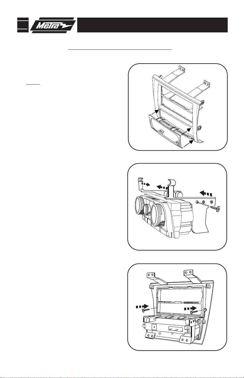
99-7423 KIT PREPARATION
NISSAN ALTIMA 2007-2011
1
Clip the corresponding climate control
trim panel into the radio housing.
Note: There are (2) different climate
control trim panels. One for auto climate control and one for manual climate control.
2
Attach the (2) radio housing brackets
to the climate controls using the factory screws.
3
Attach the bracket/climate control
assembly to the radio housing using
the (2) #8 3/8” screws supplied with
this kit.
Continue to kit assembly.
(Figure A)
(Figure B)
(Figure C)
A
B
2
C
Page 5

99-7423 KIT ASSEMBLY
DIN RADIO PROVISION WITH POCKET
*Note: Refer also to the instructions included with the aftermarket radio.
A
1
Slide the DIN cage into the Radio
Housing and secure by bending the
metal locking tabs outward.
2
Slide the aftermarket radio into the
cage until it snaps into place.
3
Attach the radio housing trim plate
supplied with the kit to the assembly.
4
Snap in the pocket into the assembly.
(Figure C)
Continue to final assembly.
(Figure A)
(Figure B)
B
3
C
Page 6

99-7423 KIT ASSEMBLY
ISO MOUNT RADIO PROVISION WITH POCKET
*Note: Refer also to the instructions included with the aftermarket radio.
A
1
Mount the ISO Brackets to the radio
with the screws supplied with the
radio.
(Figure A)
2
Slide the radio into the radio housing
until it snaps into place.
3
Attach the radio housing trim plate
supplied with the kit to the assembly.
(Figure B)
4
Snap the pocket into the assembly.
(Figure C)
Continue to final assembly.
(Figure B)
B
4
C
Page 7

99-7423 KIT ASSEMBLY
DOUBLE DIN RADIO PROVISION
*Note: Refer also to the instructions included with the aftermarket radio.
A
1
Cut and remove the center bar from
the radio housing assembly.
2
Snap the Double DIN brackets to the
inside edge of the radio housing
assembly.
3
Slide the Double DIN radio into the
bracket/radio housing assembly and
secure the radio to the assembly using
the screws supplied with the radio.
(Figure C)
4
Snap the Double DIN trim plate onto
the front of the radio/housing assembly.
Continue to final assembly.
(Figure B)
(Figure C)
(Figure A)
B
5
C
Page 8

99-7423 KIT ASSEMBLY
STACKED ISO UNITS PROVISION
*Note: Refer also to the instructions included with the aftermarket radio.
A
1
Cut and remove the center bar from
the radio housing assembly.
2
Snap the Double DIN brackets to the
inside edge of the radio housing
assembly.
3
Slide the stacked ISO units into the
bracket/radio housing assembly and
secure the units to the kit using the
screws supplied with the units.
(Figure C)
4
Snap the Double DIN trim plate onto
the front of the radio/housing assembly.
Continue to final assembly.
(Figure B)
(Figure C)
(Figure A)
B
6
C
Page 9

99-7423 FINAL ASSEMBLY
FINAL ASSEMBLY
A
(A) Strip wire ends back 1/2"
B
B) Twist ends together
C) Solder
C
D
Locate the factory wiring harness in the dash. Metra recommends using the
1
proper mating adapter and making connections as shown. (Isolate and individually tape off the ends of any unused wires to prevent electrical short circuit.)
2
Re-connect the negative battery terminal and test the unit for proper operation.
Reassemble radio and dash assemblies in reverse order of disassembly.
3
D) Tape
FINAL WIRING CONNECTIONS
Make wiring connections using the EIA color code chart shown below and the instructions included with the
head unit. Metra recommends making connections as shown below; Strip, Splice, Solder, Tape. Isolate and
individually tape off ends of any unused wires to prevent electrical short circuit.
METRA / EIA WIRING CODE
12V Ignition / Acc . . . . . . . . . . Red
12V Batt / Memory. . . . . . . . . Yellow
Ground. . . . . . . . . . . . . . . . . . Black*
Power Antenna. . . . . . . . . . . . Blue
Amp Turn-On . . . . . . . . . . . . . Blue / White
Amp Ground. . . . . . . . . . . . . . Black / White
Illumination . . . . . . . . . . . . . . Orange
Dimmer . . . . . . . . . . . . . . . . . Orange / White
Right Front (+) . . . . . . . . . . . . Gray
Right Front (-). . . . . . . . . . . . . Gray/ Black
Left Front (+) . . . . . . . . . . . . . White
Left Front (-). . . . . . . . . . . . . . White / Black
Right Rear (+) . . . . . . . . . . . . Violet
Right Rear (-) . . . . . . . . . . . . . Violet / Black
Left Rear (+) . . . . . . . . . . . . . Green
*NOTE: When a Black wire is not present, ground radio to vehicle chassis.
All colors may not be present on all leads due to manufacturer’s specifications.
7
Page 10

99-7423
NOTES
8
Page 11

99-7423
NOTES
9
Page 12

99-7423 INSTRUCTIONS
1-800-221-0932
REV. 12/10/10 © COPYRIGHT 2007-2010 METRA ELECTRONICS CORPORATION INST99-7423
www.metraonline.com
 Loading...