

Page 1
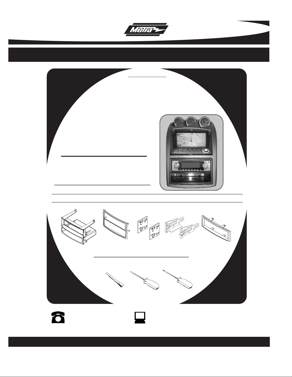
INSTALLATION INSTRUCTIONS FOR PART 99-7402
1-800-221-0932 www.metraonline.com
KIT FEATURES
© COPYRIGHT 2004 METRA ELECTRONICS CORPORATION
• DIN Radio Provision with pocket
• ISO Radio Provision with pocket
• Two stacked ISO units provision
• Double DIN radio provision
A) Radio Housing with Pocket B) Double DIN Trim-plate C) ISO Spacer Brackets D) ISO Snap-in Brackets E) ISO Trim-plate
KIT COMPONENTS
TOOLS REQUIRED:
99-7402
APPLICATIONS
350Z 2003-2005
Phillips Screwdriver
Nissan
Panel Removal Tool or
Small Flat Blade Screwdriver
B
C
E
A
D
Page 2

Dash Disassembly Nissan 350Z 2003-2005....................................1, 2
Kit Assembly
Din Mount Radio Provision with pocket..........................................................
3
ISO Mount Radio Provision with pocket..........................................................
4
Double DIN Radio..............................................................................................
5
Two Stacked ISO mount units.........................................................................
6
Final Assembly
................................................................................. 7
99-7402
TABLE OF CONTENTS
Page 3
99-7402
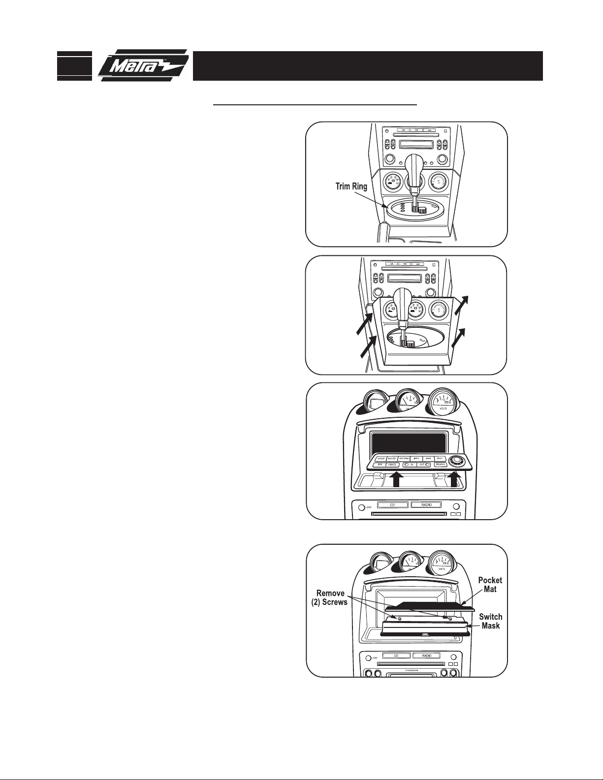
DASH DISASSEMBLY
Disconnect the negative battery
terminal to prevent an accidental
short circuit.
1
For vehicles with automatic transmission, Unsnap and remove smaller
trim-ring from around shifter.
(Figure A)
For vehicles with manual transmission, Unscrew and remove shifter
knob.
(Figure A)
2
NISSAN 350Z 2003-2005
4
For vehicles with navigation, Unsnap
and remove navigation switch panel.
(Figure C)
B
A
C
D
1
For vehicles without navigation,
remove pocket mat, then remove
two screws that secure switch
mask.
(Figure D)
3
Unsnap and remove center console
trim panel including climate controls.
(Figure B)
5
Page 4
99-7402
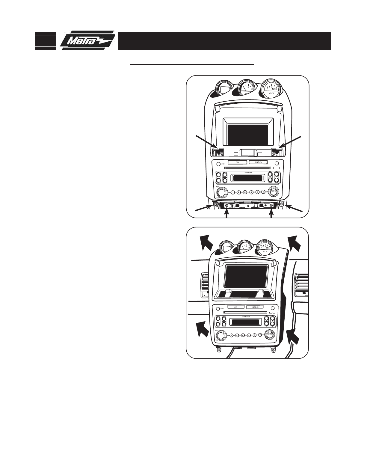
DASH DISASSEMBLY
6
Remove (2) screws above the radio
and (2) screws below the radio. Also
remove (2) screws securing the
radio/trim panel assembly.
(Figure E)
7
NISSAN 350Z 2003-2005
Remove (4) screws securing the
radio to the trim panel and remove
the radio.
F
E
2
Remove (8) screws securing the
factory brackets to the radio and
remove the brackets from the
radio. (These brackets are required
for stacked ISO and double DIN
installations. You can skip this step
for DIN or ISO installations with
pocket).
8
Unplug and remove the radio / trim
panel assembly.
(Figure F)
9
Con
tinue to kit assembly.
Page 5

Attach the radio / housing assembly
to the radio trim panel using the
factory screws removed during
disassembly.
(Figure C)
1
Slide the radio into the DIN cage until
it snaps into place.
(Figure B)
4
99-7402
KIT ASSEMBLY
Secure DIN cage to radio housing by
bending the locking tabs outward.
(Figure A)
3
Continue to final assembly.
C
2
A
DIN MOUNT RADIO PROVISION WITH POCKET
B
3
Slide DIN cage (supplied with radio)
into the radio housing from the front.
(Figure A)
Page 6

Snap the ISO trim-plate onto the front
of the assembled radio and housing.
(Figure B)
3
4
NOTE: To remove the radio unsnap and
remove the ISO trim-plate. Using a flat
blade screwdriver disengage ISO
brackets from the radio housing and
slide radio out of radio housing.
99-7402
KIT ASSEMBLY
Continue to final assembly.
Align the holes in the ISO brackets with
the holes in the radio. Mount the
brackets to the radio using screws
supplied with the radio.
(Figure A)
1
Slide the radio bracket assembly into
the radio housing until it snaps into
place.
(Figure B)
2
C
A
B
ISO MOUNT RADIO WITH POCKET
4
Attach the radio / housing assembly
to the radio trim panel using the
factory screws removed during
disassembly.
(Figure C)
Page 7

Place one of the ISO spacer brackets
and the left factory mounting bracket
(removed from radio during disassembly) on the left side of the radio.
The spacer bracket should be
between the radio and the factory
bracket. Align the pins on the trimplate with the holes on the factory
bracket and mount the factory
bracket to the radio using screws
supplied with the radio.
(Figure B)
3
5
99-7402
KIT ASSEMBLY
Continue to final assembly.
Cut and remove center divider from
double DIN trim-plate.
(Figure A)
1
Place the double DIN trim-plate on
the front of the radio.
(Figure B)
2
C
A
B
DOUBLE DIN RADIO
5
Attach the radio bracket assembly to
the radio trim panel using the
factory screws removed during
disassembly.
(Figure C)
4
Place one of the ISO spacer brackets
and the right factory mounting
bracket (Removed from radio during
disassembly) on the right side of the
radio. (The spacer bracket should be
between the radio and the factory
bracket.) Align the pins on the trimplate with the holes on the factory
bracket and mount the factory
bracket to the radio using screws
supplied with the radio.
(Figure B)
Page 8

Place one of the ISO spacer brackets and the left factory mounting
bracket (Removed from radio during
disassembly) on the left side of the
ISO units. (The spacer bracket
should be between the ISO units
and the factory bracket.) Align the
pins on the trim-plate with the
holes on the factory bracket and
mount the factory bracket to the
ISO units using screws supplied
with the radio.
(Figure A)
4
99-7402
KIT ASSEMBLY
Continue to final assembly.
Place the double DIN trim-plate on
the front of the two ISO units.
(Figure A)
1
2
A
B
TWO STACKED ISO MOUNT UNITS
6
Attach the assembled units and
brackets to the radio trim panel using
the factory screws removed during
disassembly.
(Figure B)
3
Place one of the ISO spacer brackets
and the right factory mounting
bracket (Removed from radio during
disassembly) on the right side of the
ISO units. (The spacer bracket
should be between the ISO units and
the factory bracket.) Align the pins
on the trim-plate with the holes on
the factory bracket and mount the
factory bracket to the ISO units using
screws supplied with the radio.
(Figure A)
Page 9

FINAL ASSEMBLY
1
Locate the factory wiring harness in the dash and make the connection as shown.
Metra recomends using the proper mating adapter and making the connections as
shown. (Isolate and individually tape off the ends of any unused wires to prevent
electrical short circuit.)
2
Re-connect the negative battery terminal and test the unit for proper operation.
Reassemble radio and dash assemblies in reverse order of disassembly.
A
A) Strip wire ends back 1/2"
B) Twist ends together
C) Solder
D) Tape
B
C
D
Make wiring connections using the EIA color code chart shown below and the instructions included with the head
unit. Metra recommends making connections as shown below; Strip, Splice, Solder, Tape. Isolate and individually
tape off ends of any unused wires to prevent electrical short circuit.
12V Ignition / Acc . . . Red
12V Batt / Memory . . Yellow
Ground . . . . . . . . . . . Black*
Power Antenna . . . . . Blue
Amp Turn-On . . . . . . Blue / White
Amp Ground . . . . . . . Black / White
Illumination. . . . . . . . Orange
Dimmer . . . . . . . . . . Orange / White
Right Front (+) . . . . . Gray
Right Front (-) . . . . . . Gray / Black
Left Front (+) . . . . . . White
Left Front (-) . . . . . . . White / Black
Right Rear (+). . . . . . Violet
Right Rear (-) . . . . . . Violet / Black
Left Rear (+) . . . . . . . Green
Left Rear (-) . . . . . . . Green / Black
*NOTE: When a Black wire is not present, ground radio to vehicle chassis.
All colors may not be present on all leads due to manufacturer’s specifications.
METRA / EIA WIRING CODE
FINAL WIRING CONNECTIONS
99-7402
FINAL ASSEMBLY
3
7
Page 10

99-7402
NOTES
8
Page 11

99-7402
NOTES
9
Page 12

99-7402 INSTRUCTIONS
1-800-221-0932 www.metraonline.com
© COPYRIGHT 2004 METRA ELECTRONICS CORPORATION INST99-7402
REV. 05/05/06
 Loading...