

Page 1
INST 7400
KIT COMPONENTS
6
Fig. A
Shaft
Masks
Fig. B
IF AN EQUALIZER WILL BE INCLUDED: Slide the aftermarket equalizer into the back of the
kit. Using the hardware included with the equalizer, mount the unit to the kit. (see Fig. A)
IF AN EQUALIZER WILL NOT BE INCLUDED: Snap the Equalizer Dummy Plate into the
opening in the kit. (see Fig. B)
7
A
B
C
D
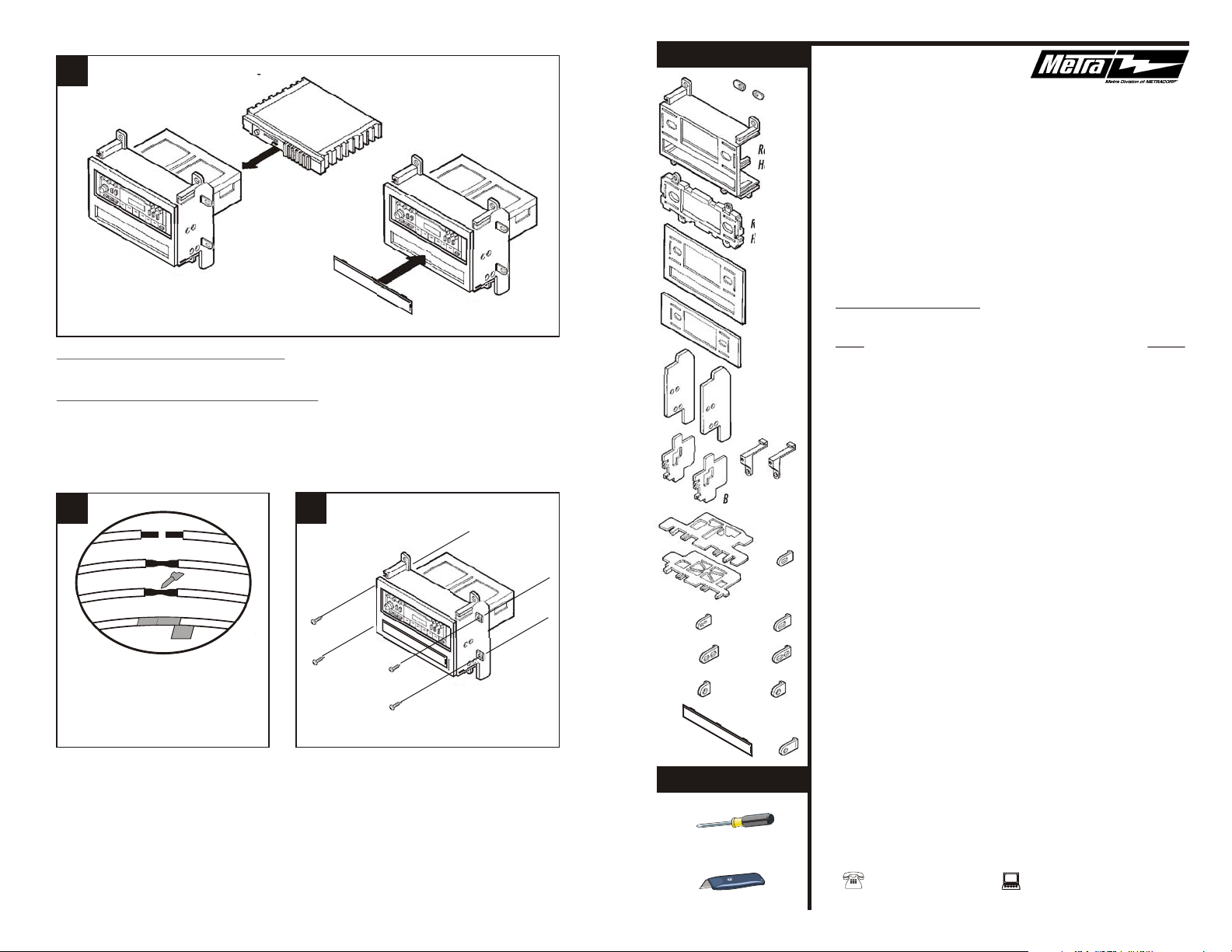
A) Strip wire ends back ½"
B) Twist ends together
C) Solder
D) Tape
Locate the factory wiring harness in the
dash. Metra recommends using the
proper mating adaptor and making
connections as shown. (Isolate and
individually tape off the ends of any
unused wires to prevent electrical short
circuit).
8
Re-connect the battery terminal and test the unit
for proper operation. Mount the head unit/kit
assembly to the sub-dash with those screws
previously removed in step #1.
Radio
Housing #1
Radio
Housing #2
Faceplate #1
Faceplate #2
Bracket Set #9
Bracket
Set #17
Bracket Set #12
Bracket #13
& #14
Mounting
Tabs #8
Mounting
Tabs #6
Mounting
Tabs #18
Mounting
Tabs #5
Equalizer
Dummy Plate
TOOLS REQUIRED
Mounting
Tabs #16
Mounting
Tabs #3
Mounting
Tabs #7
Mounting
Tabs #1
Phillips screwdriver
99-7400
INSTALLATION
INSTRUCTIONS
APPLICATIONS
CAR PAGE
NISSAN
200SX 1980-83.............................................................................1
200SX 1984-88.............................................................................2
240SX 1989-94.............................................................................3
Axxess 1989-90............................................................................ 4
Hardbody Pickup 1986.5-93..........................................................5
Maxima 1982-84.......................................................................... 6
Maxima 1987-88.......................................................................... 7
Maxima 1989-91.......................................................................... 8
Pathfinder 1987-93.......................................................................5
Pulsar 1983-86............................................................................. 9
Pulsar 1987-90............................................................................. 10
Sentra 1982-86.............................................................................9
Sentra 1987-90.............................................................................11
Stanza 1982-86.............................................................................12
Stanza 1987-89.............................................................................13
15
rev. 201202
Cutting tool
1-800-221-0932 www.metraonline.com
© COPYRIGHT 2001 METRA ELECTRONICS CORPORATION
Page 2
NISSAN 200SX 1980-83
ALL VEHICLES
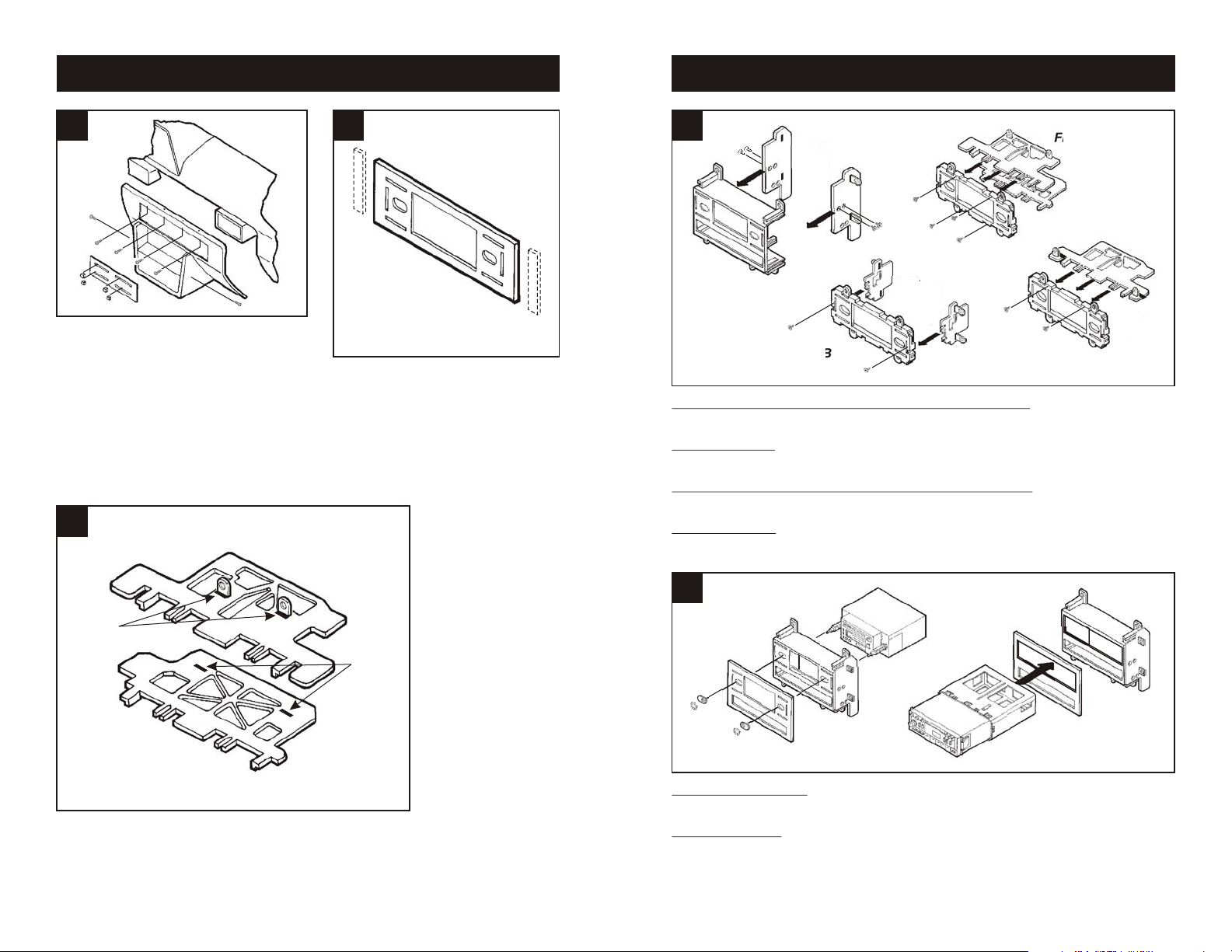
1
Disconnect the negative battery terminal to
prevent an accidental short circuit. Remove
(4) Phillips screws above the radio opening.
Remove (1) Phillips screw below the left side of
the radio opening. Remove (1) Phillips screw
from each side of the dash trim bezel. Pull off
the climate control knobs and remove the
climate control trim panel. Remove the
ashtray and lift the dash trim bezel off.
Remove (4) Phillips screws securing the
factory head unit and disconnect the wiring.
3
2
Using the scored lines as a guide, cut and
remove the dashed portions of Faceplate
#2.
4
Fig. A
Fig. B
MAXIMA 1987-91, PULSAR 1987-90, STANZA 1987-89, 240SX: Mount Bracket Set #9 to
Radio Housing #1 with (4) Phillips Pan-head Screws supplied. (see Fig. A)
SENTRA 1987-90: Mount Bracket Set #12 to Radio Housing #2 with (2) Phillips Pan-head
Screws supplied. (see Fig. B).
STANZA 1982-86, 200SX, HARDBODY PICKUP, PATHFINDER: Mount Bracket #13 and
#14 to Radio Housing #2 with (4) Phillips Pan-head Screws supplied. (see Fig. C)
MAXIMA 1982-84: Mount Bracket #14 to Radio Housing #2 with (2) Phillips Pan-head
Screws supplied. (see Fig. D)
Fig. C
Fig. D
"A"
"A"
Slide Mounting Tabs #5 into slots "A" on Brackets #13 and #14.
The Mounting Tabs, Brackets and Bracket slots can be identified
by the stamped letter on each component. Skip to the Installation
Instructions for ALL VEHICLES on Page #14.
1
5
Fig. A
Fig. B
2-SHAFT HEAD UNITS: Snap the Faceplate onto the front of the Radio Housing. Slide the
aftermarket head unit into the kit and secure with shaft nuts. (see Fig. A)
DIN HEAD UNITS: Cut and remove the shaft supports from the Faceplate and Radio
Housing. Snap the Faceplate onto the front of the Housing. Slide the DIN cage into the kit and
secure by bending the metal locking tabs down. Slide the aftermarket head unit into the cage
until secure. (see Fig. B)
14
Page 3
NISSAN Stanza 1987-89
NISSAN 200SX 1984-88
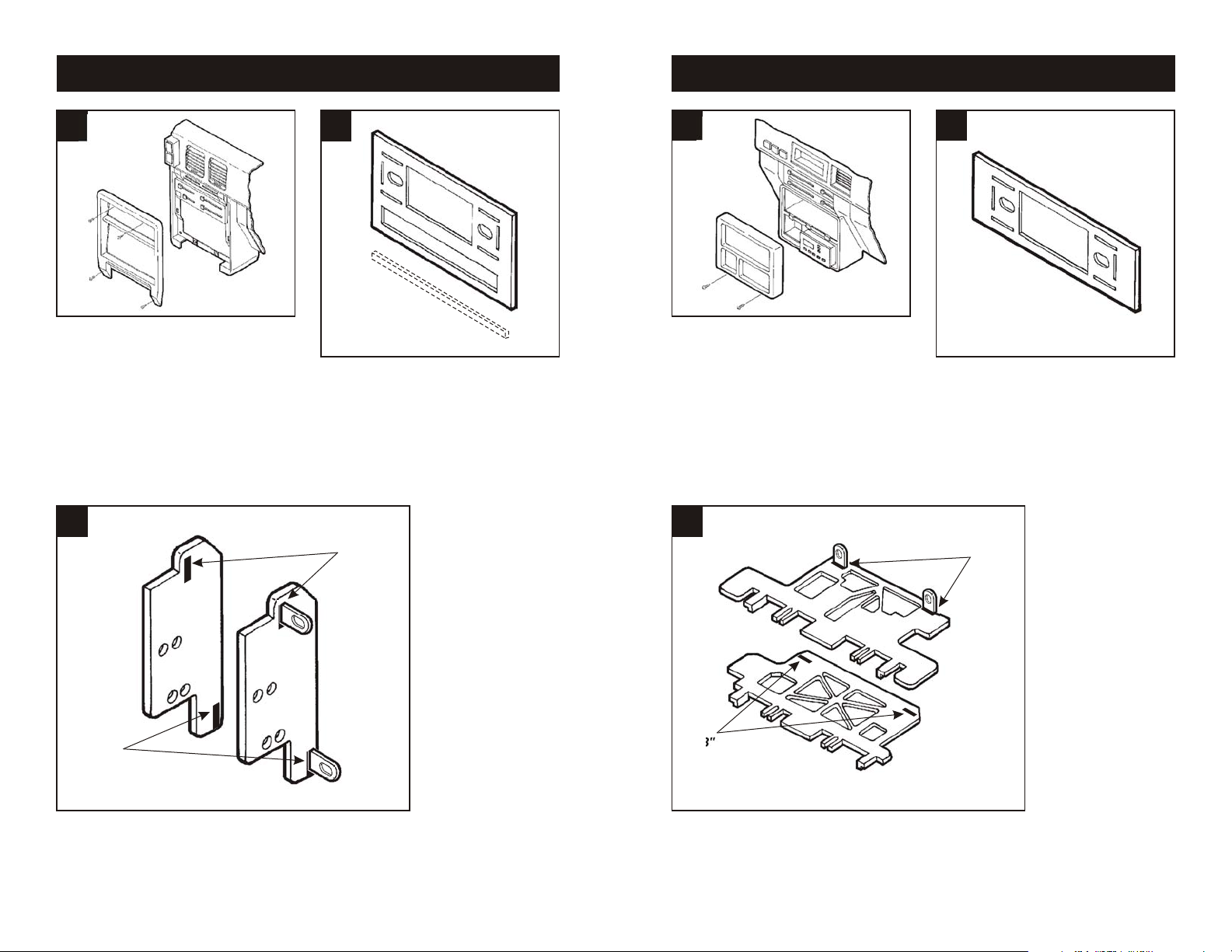
1
Disconnect the negative battery terminal to
prevent an accidental short circuit. Remove
the ashtray and (2) screws exposed at the
base of the dash trim bezel. Remove (2)
screws above the climate controls and
unclip the bezel. Remove (4) screws
securing the factory head unit and
disconnect the wiring.
3
2
Using the scored lines as a guide, cut and
remove the dashed portions of Faceplate
#1.
"B"
1
Disconnect the negative battery terminal to
prevent an accidental short circuit. Remove
(1) #10 Phillips screw from each side of the
center console. Unsnap the coin tray and
remove (2) #10 Phillips screws exposed. Lift
the storage box carpet out and remove (2)
#10 Phillips screws exposed. Remove the
ashtray and (2) #8 Phillips screws exposed.
Remove the dash trim bezel. Remove (4)
screws securing the factory head unit and
disconnect the wiring.
3
2
Locate Faceplate #2. (It is NOT necessary
to cut the Faceplate).
"B"
"B"
Slide Mounting Tabs #8 into slots "B" on Bracket Set #9. The
Mounting Tabs, Bracket and Bracket slots can be identified by the
stamped letter on each component. Skip to the Installation
Instructions for ALL VEHICLES on Page #14.
13
"B"
Slide Mounting Tabs #8 into slots "B" on Brackets #13 and #14.
The Mounting Tabs, Brackets and Bracket slots can be identified
by the stamped letter on each component. Skip to the Installation
Instructions for ALL VEHICLES on Page #14.
2
Page 4

NISSAN 240SX 1989-94
NISSAN Stanza 1982-86
1
Disconnect the negative battery terminal to
prevent an accidental short circuit. Unclip
the dash trim bezel and remove. Remove
(4) Phillips screws securing the factory head
unit and disconnect the wiring.
3
Fig. A
2
Using the scored lines as a guide, cut and
remove the dashed portions of Faceplate
#1.
1
Disconnect the negative battery terminal to
prevent an accidental short circuit. Remove
(3) screws from the top of the dash trim
bezel. Remove (1) screw from each side of
the ashtray housing. Remove (3) screws
from the factory dummy plate. (The factory
pocket will remain intact).
3
2
Using the scored lines as a guide, cut and
remove the dashed portions of
Faceplate #2.
Fig. B
"C"
Align Bracket Set #17 with the lower mounting positions on Radio Housing #1, slide the
Brackets over the bottom shelf of the Housing and secure with (2) Phillips Pan-head Screws
supplied. (see Fig. A). Slide Mounting Tabs #18 into slots "C" on Bracket Set #9. (see Fig.
B). The Mounting Tabs, Brackets and Bracket slots can be identified by the stamped letter on
each component. Skip to the Installation Instructions for ALL VEHICLES on Page #14.
3
"D"
"C"
Slide Mounting Tab #1 into slot "D" on Bracket #14. Slide
Mounting Tabs #8 into slots "C" on Bracket #13. The Mounting
Tabs, Brackets and Bracket slots can be identified by the stamped
letter on each component. Skip to the Installation Instructions for
ALL VEHICLES on Page #14.
12
Page 5

NISSAN Sentra 1987-90
NISSAN Axxess 1989-90
1
Disconnect the negative battery terminal to
prevent an accidental short circuit. Remove
the ashtray. Remove (2) screws above the
climate controls. Remove (2) screws from
the base of the dash trim bezel and remove
the bezel. Remove the screws securing the
factory head unit and disconnect the wiring.
3
2
Locate Faceplate #2. (It is NOT necessary
to cut the Faceplate).
"E"
1
Disconnect the negative battery terminal to
prevent an accidental short circuit. Remove (2)
screws from the top of the dash trim bezel and
remove the bezel. Remove (4) fasteners from
the factory head unit and disconnect the wiring.
3
2
Using the scored lines as a guide, cut
and remove the dashed portions of
Faceplate #1.
"E"
Slide Mounting Tabs #8 into slots "E" on Bracket Set #12. The
Mounting Tabs, Bracket and Bracket slots can be identified by the
stamped letter on each component. Skip to the Installation
Instructions for ALL VEHICLES on Page #14.
11
Locate Radio Housing #2 and use the attached mounting tabs
during the installation in step #8. (It is NOT necessary to mount
Brackets to the Housing). Skip to the Installation Instructions for
ALL VEHICLES on Page #14.
4
Page 6

NISSAN Hardbody Pickup / Pathfinder 1986 1/2-93
NISSAN Pulsar 1987-90
1
Disconnect the negative battery terminal to
prevent an accidental short circuit. Remove
the ashtray and (1) screw exposed in the
top-right corner. Remove (2) Phillips screws
above the climate controls. Remove (2)
Phillips screws from the bottom of the dash
trim bezel. Unsnap the bezel and
disconnect the cigarette lighter wiring.
Remove (4) screws securing the factory
head unit and disconnect the wiring.
3
2
Using the scored lines as a guide, cut and
remove the dashed portions of Faceplate
#2.
1
Disconnect the negative battery terminal to
prevent an accidental short circuit. Remove
(3) screws above the climate controls.
Remove (2) screws from the bottom edge of
the dash trim bezel. Unclip the bezel and
remove. Remove (4) screws securing the
factory head unit and disconnect the wiring.
3
2
Using the scored lines as a guide, cut and
remove the dashed portions of Faceplate
#1.
"A"
"E"
"E"
Slide Mounting Tabs #8 into slots "E" on Brackets #13 and #14.
The Mounting Tabs, Brackets and Bracket slots can be identified
by the stamped letter on each component. Skip to the Installation
Instructions for ALL VEHICLES on Page #14.
5
"A"
Slide Mounting Tabs #8 into slots "A" on Bracket Set #9. The
Mounting Tabs, Brackets and Bracket slots can be identified by the
stamped letter on each component. Skip to the Installation
Instructions for ALL VEHICLES on Page #14.
10
Page 7

NISSAN Pulsar 1983-86 / Sentra 1982-86
NISSAN Maxima 1982-84
1
Disconnect the negative battery terminal to
prevent an accidental short circuit. Remove (2)
Phillips screws from the top of the dash trim
bezel. Remove the ashtray and (1) screw
exposed on the ashtray bracket. Remove the
bracket. Unclip the dash trim bezel and
disconnect the wiring. Remove (2) Phillips
screws securing the factory head unit to the shelf.
Remove the unit and disconnect the wiring.
3
Fig. A
2
Using the scored lines as a guide, cut
and remove the dashed portions of
Faceplate #2. (This model does NOT
require the use of a Radio Housing or
Mounting Brackets).
1
Disconnect the negative battery terminal to
prevent an accidental short circuit. Remove
the knobs from the climate controls. Using a
small screwdriver, pry out on the climate
control trim panel and remove. Remove (2)
screws securing the factory dummy plate
and discard the plate.
3
2
Using the scored lines as a guide, cut and
remove the dashed portions of
Faceplate #2.
Fig. B
2-SHAFT HEAD UNITS: Slide the aftermarket head unit into the dash trim bezel, place the
Faceplate and Shaft Masks over the radio shafts and secure with shaft nuts. (see Fig. A).
Make wiring connections and re-attach the dash trim bezel.
DIN HEAD UNITS: Cut and remove the shaft supports from the Faceplate. Cut a DIN opening
in the dash trim bezel. Slide the DIN cage through the Faceplate into the dash trim bezel and
secure by bending the metal locking tabs down. Make wiring connections and slide the
aftermarket head unit into the cage until secure. (see Fig. B). Re-attach the dash trim bezel.
9
"C"
Slide Mounting Tabs #8 into slots "C" on Bracket Set #14. The
Mounting Tabs, Bracket and Bracket slots can be identified by the
stamped letter on each component. Skip to the Installation
Instructions for ALL VEHICLES on Page #14.
6
Page 8

NISSAN Maxima 1987-88
NISSAN Maxima 1989-91
1
Disconnect the negative battery terminal to
prevent an accidental short circuit. Remove
(2) Phillips screws from the bottom of the
dash trim bezel. Remove (2) Phillips screws
above the radio opening. Unclip the dash
trim bezel and disconnect the defroster and
rear wiper wiring. Remove (4) screws
securing the factory head unit and
disconnect the wiring.
3
2
Using the scored lines as a guide, cut and
remove the dashed portions of Faceplate
#1.
"E"
1
Disconnect the negative battery terminal to
prevent an accidental short circuit. Remove
(2) Phillips screws above the radio opening.
Remove the ashtray and (1) screw in the
right corner of the ashtray housing. Remove
(1) screw below the cigarette lighter and
unclip the dash trim bezel. Remove (4)
screws securing the factory head unit and
disconnect the wiring.
3
2
Using the scored lines as a guide, cut and
remove the dashed portions of
Faceplate #1.
"D"
"E"
Slide Mounting Tabs #18 into slots "E" on Bracket Set #9. The
Mounting Tabs, Bracket and Bracket slots can be identified by the
stamped letter on each component. Skip to the Installation
Instructions for ALL VEHICLES on Page #14.
7
"D"
Slide Mounting Tabs #18 into slots "D" on Brackets #9. The
Mounting Tabs, Brackets and Bracket slots can be identified by the
stamped letter on each component. Skip to the Installation
Instructions for ALL VEHICLES on Page #14.
8
 Loading...