

Page 1
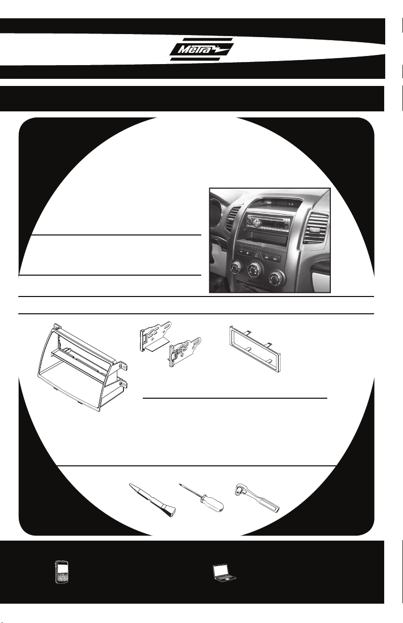
INSTALLATION INSTRUCTIONS FOR PART 99-7340B
APPLICATIONS
2011 KIA SORENTO
99-7340B
KIT FEATURES
• DIN Head unit provisions with pocket
• ISO DIN Head unit provision with pocket
• Painted Matte Black to Match Factory
KIT COMPONENTS
• A) Radio Housing • B) ISO Brackets • C) ISO Trim Plate
A
B C
WIRING & ANTENNA CONNECTIONS (Sold Separately)
• 70-7303 2009-Up Kia/Hyundai Harness
• 40-KI11 2007-Up Kia Antenna Adapter
TOOLS REQUIRED
• Panel Removal Tool • Phillips Screwdriver • Socket Wrench
METRA. THE WORLD’S BEST KITS.™
1-800-221-0932 metraonline.com
© COPYRIGHT 2004-2010 METRA ELECTRONICS CORPORATION
Page 2
INSTALLATION INSTRUCTIONS FOR PART 99-7340B
TABLE OF CONTENTS
DASH DISASSEMBLY
• 2011 KIA SORENTO . . . . . . . . . . . . . . . . . . . . . . 1-2
KIT ASSEMBLY
2011 KIA SORENTO
• DIN HEAD UNIT PROVISION . . . . . . . . . . . . . . . . . . 3
• ISO DIN HEAD UNIT PROVISION . . . . . . . . . . . . . . . 4
CAUTION: Metra recommends disconnecting the negative battery terminal
before beginning any installation. All accessories, switches, and especially
air bag indicator lights must be plugged in before reconnecting the battery
or cycling the ignition.
*NOTE: Refer also to the instructions included with the aftermarket radio.
KNOWLEDGE IS POWER
Enhance your installation and fabrication skills by
enrolling in the most recognized and respected
mobile electronics school in our industry.
Log onto www.installerinstitute.com or call
800-354-6782 for more information and take steps
toward a better tomorrow.
Metra recommends MECP certified
technicians
Page 3
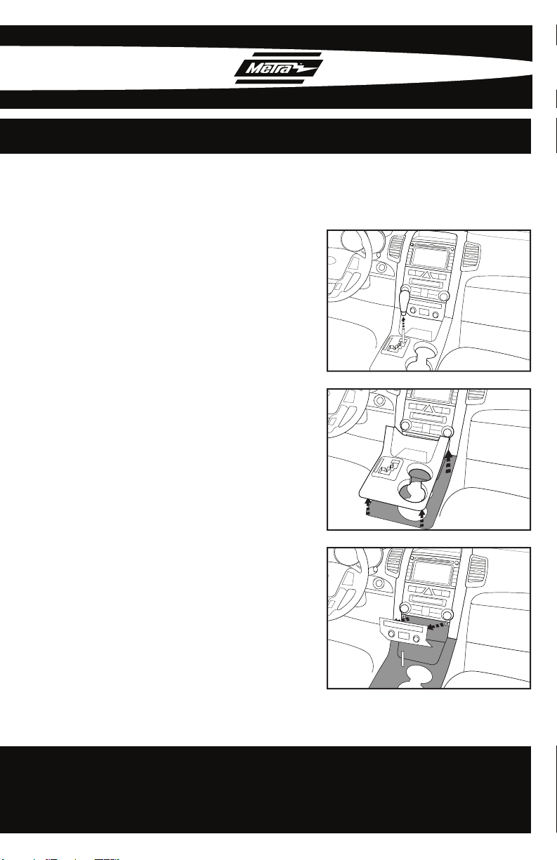
99-7340B DASH DISASSEMBLY
2011 KIA SORENTO
Remove Shifter knob. (Fig. A)
1
Remove the shifter surround panel.
2
(Fig. B)
Remove panel under the heater &
3
A/C controls. (Fig. C)
A
B
1
C
Continued on Pg. 2 .......................
Page 4

99-7340B DASH DISASSEMBLY
2011 KIA SORENTO
4
Remove (2) Phillips screws from
bottom and remove center fascia
panel. (Fig. D)
Remove (4) Phillips screws securing
5
the heater & A/C controls. (Fig. E)
Remove (4) Phillips screws securing
6
the radio. (Fig. F)
D
E
2
F
Continue to kit assembly...............
Page 5

99-7340B KIT ASSEMBLY
DIN HEAD UNIT PROVISION
Slide the DIN cage into the Radio
1
Housing and secure by bending the
metal locking tabs down. (Fig. A)
Snap the pocket into the bottom
2
opening of the radio housing.
(Fig. B)
A
Slide the aftermarket head unit into
3
the cage and secure. (Fig. B)
Locate the factory wiring harness
4
and antenna plug in the dash. Metra
recommends using the proper
mating adapters from Metra and/or
AXXESS.
Reassemble dash in reverse order
5
of disassembly.
B
3
Page 6

99-7340B KIT ASSEMBLY
ISO DIN HEAD UNIT PROVISION
Mount the ISO Brackets to the head
1
unit with the screws supplied with
the unit. (Fig. A)
Slide the head unit into the radio
2
opening until the side clips engage.
(Fig. B)
A
Snap the Trim plate into the Radio
3
Housing. (Fig. B)
Locate the factory wiring harness
4
and antenna plug in the dash. Metra
recommends using the proper
mating adapters from Metra and/or
AXXESS.
Reassemble dash in reverse order
5
of disassembly.
B
4
Page 7

INSTALLATION INSTRUCTIONS FOR PART 99-7340B
NOTES
Page 8

INSTALLATION INSTRUCTIONS FOR PART 99-7340B
REV. 6/28/2010
METRA. THE WORLD’S BEST KITS.™
1-800-221-0932 metraonline.com
© COPYRIGHT 2004-2010 METRA ELECTRONICS CORPORATION
 Loading...