

Page 1

Page 2
99-7337B
K
NOWLEDGE IS POWER
Enhance your installation and fabrication skills by
enrolling in the most recognized and respected
mobile electronics school in our industry.
Log onto www.installerinstitute.com or call
800-354-6782 for more information and take steps
toward a better tomorrow.
TABLE OF CONTENTS
Dash Disassembly
- KIA Soul 2010-11 . ........ ....... ........ ........ ....... ........ .1
Kit
Assembly
- ISO Head Unit Provision..... ........ ........ ....... ........ . ...... 2
Final
Assembly .......................................... 3
*Note:
Refer also to the instructions included with the aftermarket radio.
Metra recommends MECP certified
technicians.
Page 3
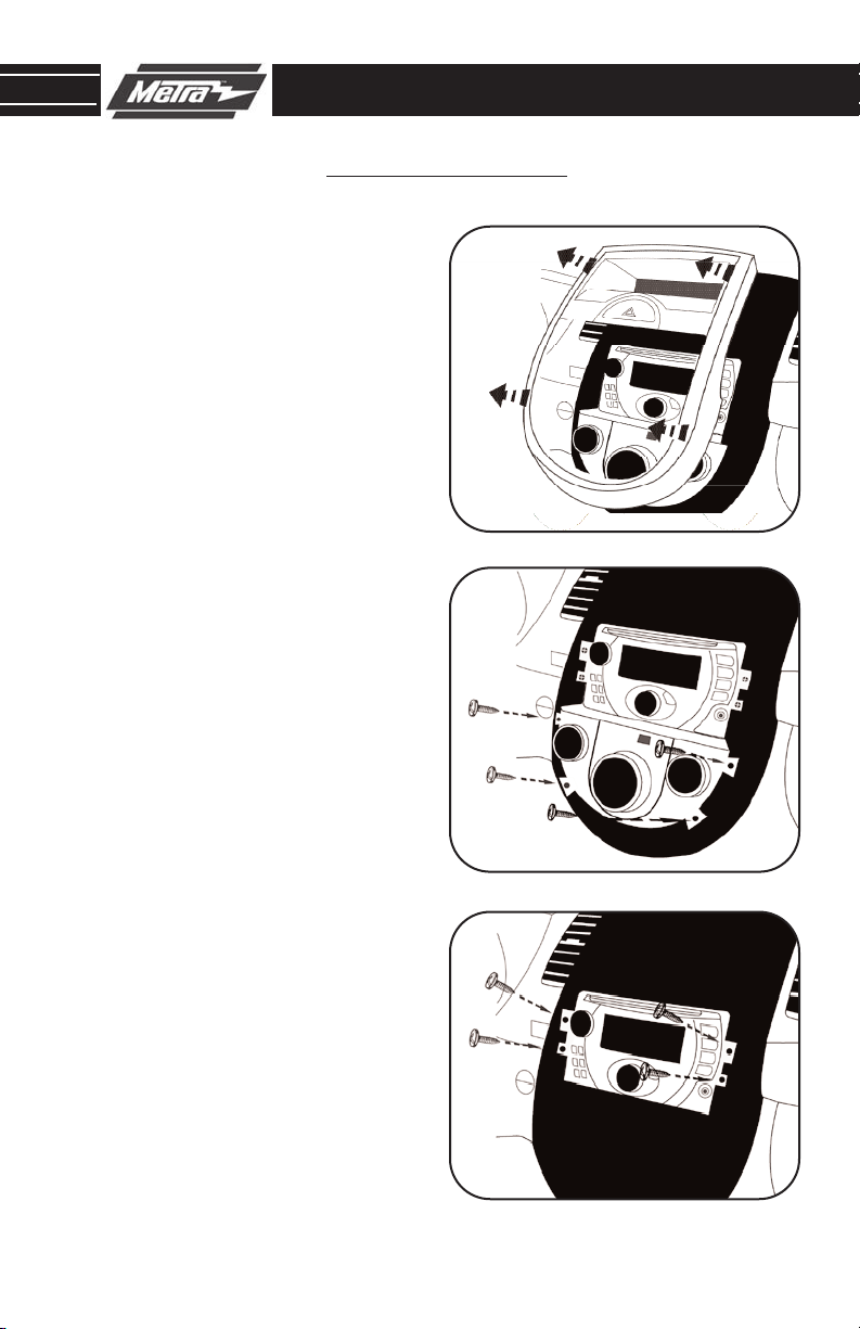
99-7337B DASH DISASSEMBLY
KIA SOUL 2010-11
Disconnect the negative battery ter-
1
minal to prevent an accidental short
circuit.
Unclip and remove the radio/climate
2
control trim panel.
Remove (4) Phillips screws securing
3
the climate control.
Remove (4) Phillips screws securing
4
the radio.
Continue to kit assembly.
(Figure C)
(Figure A)
(Figure B)
A
B
C
1
Page 4

99-7337B KIT ASSEMBLY
ISO HEAD UNIT PROVISION
*Note: Refer also to the instructions included with the aftermarket radio.
A
Attach the ISO brackets to the radio
1
housing.
2
Slide the head unit into the bracket /
radio housing assembly and secure
using the ISO screws supplied with
the radio.
Locate the factory wiring harness in
3
the dash. Metra recommends using
the proper mating adapter from
Metra or AXXESS. Re-connect the
negative battery terminal and test
the unit for proper operation.
Reassemble dash in reverse order of
4
disassembly.
(Figure A)
(Figure B)
B
Continue to final assembly.
2
Page 5

99-7337B FINAL ASSEMBLY
FINAL ASSEMBLY
A
(A) Strip wire ends back 1/2"
B
B) Twist ends together
C) Solder
C
D
Locate the factory wiring harness in the dash. Metra recommends using the
1
proper mating adapter and making connections as shown. (Isolate and individually tape off the ends of any unused wires to prevent electrical short circuit.)
Re-connect the negative battery terminal and test the unit for proper operation.
2
Reassemble radio and dash assemblies in reverse order of disassembly.
3
D) Tape
FINAL WIRING CONNECTIONS
Make wiring connections using the EIA color code chart shown below and the instructions included with the
head unit. Metra recommends making connections as shown below; Strip, Splice, Solder, Tape. Isolate and
individually tape off ends of any unused wires to prevent electrical short circuit.
METRA / EIA WIRING CODE
12V Ignition / Acc . . . . . . . . . . Red
12V Batt / Memory. . . . . . . . . Yellow
Ground. . . . . . . . . . . . . . . . . . Black*
Power Antenna. . . . . . . . . . . . Blue
Amp Turn-On . . . . . . . . . . . . . Blue / White
Amp Ground. . . . . . . . . . . . . . Black / White
Illumination . . . . . . . . . . . . . . Orange
Dimmer . . . . . . . . . . . . . . . . . Orange / White
Right Front (+) . . . . . . . . . . . . Gray
Right Front (-). . . . . . . . . . . . . Gray/ Black
Left Front (+) . . . . . . . . . . . . . White
Left Front (-). . . . . . . . . . . . . . White / Black
Right Rear (+) . . . . . . . . . . . . Violet
Right Rear (-) . . . . . . . . . . . . . Violet / Black
Left Rear (+) . . . . . . . . . . . . . Green
Left Rear (-) . . . . . . . . . . . . . . Green / Black
*NOTE: When a Black wire is not present, ground radio to vehicle chassis.
All colors may not be present on all leads due to manufacturer’s specifications.
3
Page 6

99-7337B
NOTES
4
Page 7

99-7337B
NOTES
5
Page 8

99-7337B INSTRUCTIONS
1-800-221-0932
REV. 09/01/10 © COPYRIGHT 2004-2010 METRA ELECTRONICS CORPORATION INST99-7337B
www.metraonline.com
 Loading...