

Page 1
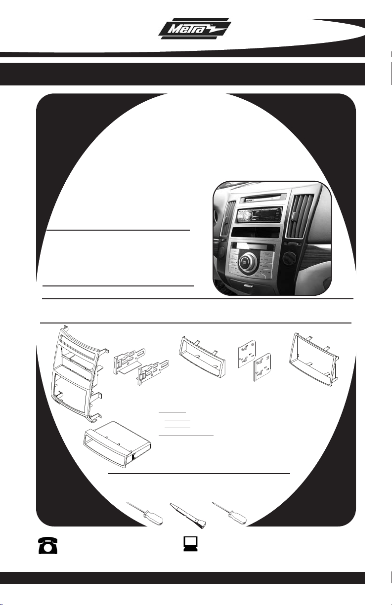
INSTALLATION INSTRUCTIONS FOR PART 99-7335S
APPLICATIONS
HYUNDAI Veracruz
2007-2010
Automatic climate control only
99-7335S
KIT FEATURES
• DIN Radio Provision with Pocket
• ISO Mount Radio Provision with Pocket
• Double DIN Radio Provision
• Stacked ISO Mount Units Provision
Painted to match factory dash-”S”=Silver
•
KIT COMPONENTS
• A) Radio Housing • B) ISO Brackets • C) ISO Trim Plate • D) Double DIN Brackets
• E) Double DIN Trim Plate • F) Pocket
A
B
WIRING AND ANTENNA CONNECTIONS (Sold Separately)
Harness:
• 70-1004 - KIA/Hyundai harness 2004-up
• 70-7303 - KIA/Hyundai harness 2009
Antenna Adapter:
• 40-KI11 - KIA antenna adapter 2007-up
F
Small Flat Blade Screwdriver/ Panel Removal Tool
TOOLS REQUIRED:
• Phillips Screwdriver
1-800-221-0932
© COPYRIGHT 2009 METRA ELECTRONICS CORPORATION
C
D
E
www.metraonline.com
Page 2
99-7335S
K
NOWLEDGE IS POWER
Enhance your installation and fabrication skills
by enrolling in the most recognized and respected
mobile electronics school in our industry.
Log onto www.installerinstitute.com
or call 800-354-6782 for more information
and take steps toward a better tomorrow.
TABLE OF CONTENTS
Dash Disassembly
-
Hyundai Veracruz 2007-2010
(Automatic climate control only) .......................
. .1
Kit Assembly
- Kit Preparation . . . . . . . . . . . . . . . . . . . . . . . . . . . . . . . . . . . . . . . . . . 2
- DIN Mount Radio Provision with Pocket . . . . . . . . . . . . . . . . . . . . . . . .3
- ISO Mount Radio Provision with Pocket . . . . . . . . . . . . . . . . . . . . . . . . 4
Note:
Refer also to the instructions included with the aftermarket radio.
Page 3
95-7335S DASH DISASSEMBLY
CLOCK DISPLAY-REAR VIEW
CLIMATE CONTROL-REAR VIEW
RADIO HOUSING
REAR VIEW
POCKET-R EAR VIEW
HYUNDAI VERACRUZ 2007-2010
Disconnect the negative battery
1
terminal to prevent an accidental short
circuit.
Unclip and remove the side trim
2
panels. (Tip: start at the bottom of the
panels)
Remove (6) Phillips head screws
3
securing the radio trim panel and
remove trim panel.
Remove (4) Phillips screws securing
4
the climate control, (2) Phillips screws
securing the clock display and (4)
Phillips screws securing the pocket
from the radio trim panel.
Continue to kit preparartion.
(Figure A)
(Figure B)
(Figure C)
C
A
B
1
Page 4

99-7335S KIT ASSEMBLY
H
M
R
PUS
H
A/
C
TEM
P
PASSEN
GER
DUA
L
REA
R
REA
R
FRO
NT
MOD
E
OFF
AUT
O
A
MAN
UAL
TEMP
KIT PREPARATION
Attach the climate control, pocket and the clock display into the 99-7335S radio
1
housing using the factory hardware. (
Continue to kit assembly.
A
Figure A)
2
Page 5

99-7335S KIT ASSEMBLY
DIN MOUNT RADIO PROVISION WITH POCKET
*
Note: Refer also to the instructions included with the aftermarket radio.
A
Locate the factory wiring harness in
1
the dash. Metra recommends using
the proper mating adapter from Metra
or AXXESS. Re-connect the negative
battery terminal and test the unit for
proper operation.
Slide the DIN cage into the Radio
2
Housing and secure by bending the
metal locking tabs down.
Snap the pocket into the bottom
3
opening of the radio housing.
(Figure B)
Slide the aftermarket head unit into
4
the cage and secure.
(Figure A)
B
(Figure C)
Reassemble dash in reverse order of
5
disassembly.
C
3
Page 6

99-7335S KIT ASSEMBLY
ISO MOUNT RADIO PROVISION WITH POCKET
*
Note: Refer also to the instructions included with the aftermarket radio.
A
Locate the factory wiring harness in
1
the dash. Metra recommends using
the proper mating adapter from Metra
or AXXESS. Re-connect the negative
battery terminal and test the unit for
proper operation.
Mount the ISO Brackets to the head
2
unit with the screws supplied with
the unit.
Snap the pocket into the bottom
3
opening of the radio housing.
(Figure B)
Slide the head unit into the radio
4
opening until the side clips engage.
(Figure C)
(Figure A)
B
Snap the Trim plate into the Radio
5
Housing.
Reassemble dash in reverse order of
6
disassembly.
(Figure C)
C
4
Page 7

99-7335S KIT ASSEMBLY
DOUBLE DIN/STACKED ISO MOUNT
UNITS RADIO PROVISION
*
Note: Refer also to the instructions included with the aftermarket radio.
A
Locate the factory wiring harness in
1
the dash. Metra recommends using
the proper mating adapter from Metra
or AXXESS. Re-connect the negative
battery terminal and test the unit for
proper operation.
Cut and remove the center bar from
2
the radio housing.
Snap the Double DIN brackets to the
3
inside edge of the Double DIN trim
(Figure B)
plate.
Slide the Double DIN head unit or
4
stacked ISO head units into the
bracket/radio housing assembly and
secure the Double DIN head unit or
stacked ISO head units to the
assembly using the screws supplied
with the radio.
(Figure A)
B
(Figure C)
Snap the Double DIN trim plate into the
5
Radio Housing.
Reassemble dash in reverse order of
6
disassembly.
(Figure C)
C
5
Page 8

99-7335S INSTRUCTIONS
1-800-221-0932
REV. 09/02/09 © COPYRIGHT 2009 METRA ELECTRONICS CORPORATION INST99-7335S
www.metraonline.com
 Loading...