

Page 1
INSTALLATION INSTRUCTIONS FOR PART 99-7011
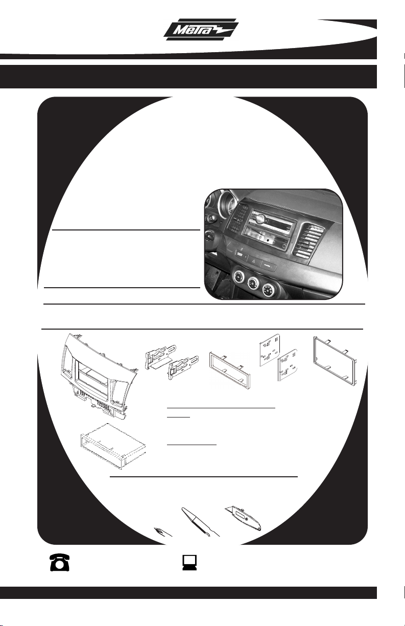
APPLICATIONS
MITSUBISHI Lancer
2008-2010
99-7011
KIT FEATURES
• DIN Radio Provision with Pocket
• ISO Mount Radio Provision with Pocket
• Double DIN Radio Provision
• Stacked ISO Mount Units Provision
• Painted to Match Factory
KIT COMPONENTS
• A) Radio Housing • B) ISO Brackets • C) Trim Plate • D) Double DIN Brackets
• E) Double DIN Trim Plate • F) Snap in Pocket
B
A
F
Phillips Screwdriver/ Panel Removal Tool
1-800-221-0932
© COPYRIGHT 2008-2009 METRA ELECTRONICS CORPORATION
D
C
WIRING AND ANTENNA CONNECTIONS: (Sold Separately)
:
Harness
• MITO-02 - Mitsubishi amp interface harness 2007-up
• 70-7005 - Mitsubishi harness 2007-up
Antenna Adapter:
• No antenna adapter required
TOOLS REQUIRED:
• Cutting Tool
E
www.metraonline.com
Page 2
99-7011
K
NOWLEDGE IS POWER
Enhance your installation and fabrication skills by
enrolling in the most recognized and respected
mobile electronics school in our industry.
Log onto www.installerinstitute.com or call
800-354-6782 for more information and take
steps toward a better tomorrow.
TABLE OF CONTENTS
Dash Disassembly
-
Mitsubishi Lancer 2008-2010 . . . . . . . . . . . . . . . . . . .
. ... . 1,2
Kit Preparation . . . . . . . . . . . . . . . . . . . . . . . . . . . . . . . . . . . . . . . . . . . .3
Kit
Assembly
- DIN Radio Provision with Pocket . . . . . . . . . . . . . . . . . . . . . . . . . . . . .4
- ISO Mount Radio Provision with Pocket. . . . . . . . . . . . . . . . . . . . . . . . 5
- Double DIN Radio Provision/Stacked ISO Mount Units Provision . . . . . . 6
Final
Assembly . . . . . . . . . . . . . . . . . . . . . . . . . . . . . . . . . . . . . . . . . . .7
Note:
Refer also to the instructions included with the aftermarket radio.
Page 3
99-7011 DASH DISASSEMBLY
MITSUBISHI LANCER 2008-2010
Disconnect the negative battery ter-
1
minal to prevent an accidental short
circuit.
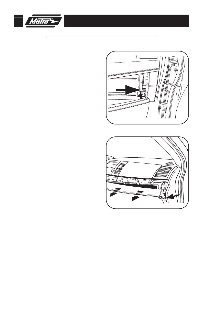
Open the glove box and remove (1)
2
Phillips screw from the panel to the
right of the glove box door. Unclip
and remove the panel.
3
Remove (1) Phillips screw from the
panel above the glove box then
unclip and remove the panel.
(Figure B)
Continued on page 2.
(Figure A)
A
B
1
Page 4
99-7011 DASH DISASSEMBLY
PAS
SEN
GER
AIRBA
G
O
FF
PASSENGER
PAS
S
E
NG
ER
AI
R
B
AG
OF
F
PASSENGER
MITSUBISHI LANCER 2008-2010
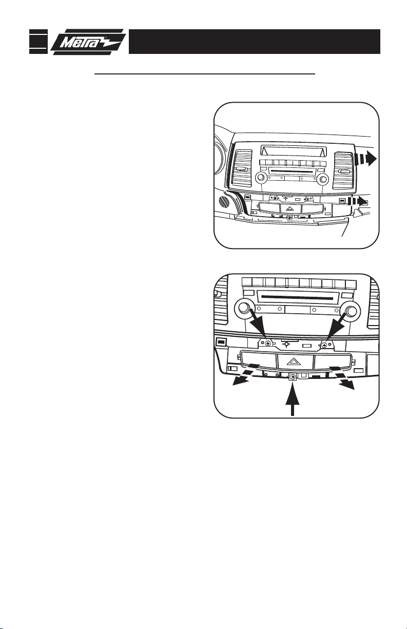
4
Unclip the radio switch panel including the hazard switch assembly.
Unplug hazard switch assembly and
remove panel.
5
Remove (4) Phillips screws securing the radio chassis. Unplug and
remove chassis.
6
Remove (3) Phillips screws securing
the hazard switch assembly to the
factory radio switch panel. Unclip
and remove the switch.
7
Unclip assembly, unplug ribbon
cable from assembly and remove
assembly from the factory radio
panel. Retain screws and hazard
switch assembly for re-use during
kit preparation.
(Figure C)
(Figure D)
C
D
8
Unclip and remove the a/c vents
from the factory radio switch panel.
(Retain a/c vents for re-use during
kit preparation)
9
Remove and retain (7) factory clips
from rear of radio housing for
re-use during kit preparation.
Continue to kit prepar
ation.
2
Page 5

99-7011 KIT PREPARATION
PAS
SE
N
GER
PAS
SEN
G
ER
A
IR
B
AG
OF
F
REAR VIEW OF RADIO HOUSING
MITSUBISHI LANCER 2008-2010
1
Secure the hazard switch assembly into the radio housing using the factory hardware. Snap the a/c vents into the radio housing.
Use the (7) plastic factory clips previously removed during dash disassembly and
2
attach where shown.
(Figure B)
Continue to kit assembly
A
(Figure A)
B
3
Page 6

99-7011 KIT ASSEMBLY
DIN RADIO PROVISION WITH POCKET
*Note: Refer also to the instructions included with the aftermarket radio.
A
Slide the DIN cage into the Radio
1
Housing and secure by bending the
metal locking tabs outward.
Slide the aftermarket radio into the
2
cage until it snaps into place.
(Figure B)
Snap the pocket into the radio hous-
3
ing.
(Figure C)
(Figure A)
Continue to final assembly.
B
C
4
Page 7

99-7011 KIT ASSEMBLY
ISO MOUNT RADIO PROVISION WITH POCKET
*Note: Refer also to the instructions included with the aftermarket radio.
A
Mount the ISO Brackets to the radio
1
using the screws supplied with the
radio.
(Figure A)
Slide the radio into the radio housing
2
until it snaps into place.
Snap the trim plate onto the front of
3
the radio housing.
4
Snap the Pocket into the radio housing.
(Figure C)
Continue to final assembly.
(Figure B)
(Figure B)
B
5
C
Page 8

99-7011 KIT ASSEMBLY
DOUBLE DIN RADIO PROVISION
STACKED ISO MOUNT UNITS PROVISION
*Note: Refer also to the instructions included with the aftermarket radio.
A
1
Cut and remove the center bar from
the radio housing.
Snap the Double DIN brackets to the
2
inside edge of the radio housing.
(Figure B)
3
Slide the Double DIN or stacked ISO
mount unit(s) into the bracket/radio
housing assembly and secure the
unit(s) to the assembly using the
screws supplied with the unit(s).
(Figure C)
4
Snap the Double DIN trim plate onto
the front of the radio housing.
(Figure C)
(Figure A)
B
Continue to final assembly.
C
6
Page 9

99-7011 FINAL ASSEMBLY
FINAL ASSEMBLY
A
(A) Strip wire ends back 1/2"
B
B) Twist ends together
C) Solder
C
D
Locate the factory wiring harness in the dash. Metra recommends using the
1
proper mating adapter and making connections as shown. (Isolate and individually tape off the ends of any unused wires to prevent electrical short circuit.)
Re-connect the negative battery terminal and test the unit for proper operation.
2
Reassemble radio and dash assemblies in reverse order of disassembly.
3
D) Tape
FINAL WIRING CONNECTIONS
Make wiring connections using the EIA color code chart shown below and the instructions included with the
head unit. Metra recommends making connections as shown below; Strip, Splice, Solder, Tape. Isolate and
individually tape off ends of any unused wires to prevent electrical short circuit.
METRA / EIA WIRING CODE
12V Ignition / Acc . . . . . . . . . . Red
12V Batt / Memory. . . . . . . . . Yellow
Ground. . . . . . . . . . . . . . . . . . Black*
Power Antenna. . . . . . . . . . . . Blue
Amp Turn-On . . . . . . . . . . . . . Blue / White
Amp Ground. . . . . . . . . . . . . . Black / White
Illumination . . . . . . . . . . . . . . Orange
Dimmer . . . . . . . . . . . . . . . . . Orange / White
Right Front (+) . . . . . . . . . . . . Gray
Right Front (-). . . . . . . . . . . . . Gray/ Black
Left Front (+) . . . . . . . . . . . . . White
Left Front (-). . . . . . . . . . . . . . White / Black
Right Rear (+) . . . . . . . . . . . . Violet
Right Rear (-) . . . . . . . . . . . . . Violet / Black
Left Rear (+) . . . . . . . . . . . . . Green
Left Rear (-) . . . . . . . . . . . . . . Green / Black
*NOTE: When a Black wire is not present, ground radio to vehicle chassis.
All colors may not be present on all leads due to manufacturer’s specifications.
7
Page 10

99-7011
NOTES
8
Page 11

99-7011
NOTES
9
Page 12

99-7011 INSTRUCTIONS
1-800-221-0932
REV. 04/21/10 © COPYRIGHT 2008-2010 METRA ELECTRONICS CORPORATION INST99-7011
www.metraonline.com
 Loading...