

Page 1
INSTALLATION INSTRUCTIONS FOR PART 99-6537B
METRA – The World’s best kits.
®
CAUTION!
All accessories, switches, climate controls panels,
and especially air bag indicator lights must be connected before
cycling the ignition. Also, do not remove the factory radio with
the key in the on position, or while the vehicle is running.
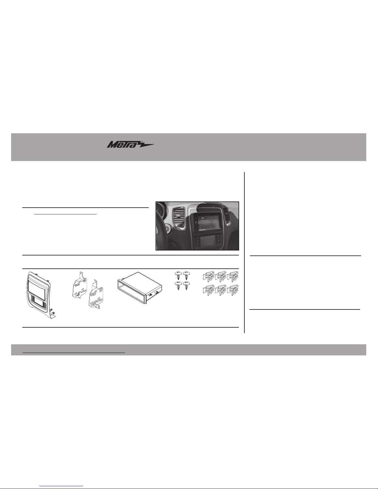
• ISO DIN radio provision with pocket
• ISO DDIN radio provision
• Painted Black
• Touchscreen display for climate and
personalization features
• A) Radio trim panel with touchscreen display • B) Radio brackets • C) Pocket
• D) (4) #8 x 3/8” Phillips screws • E) (6) Panel clips • F) HVAC interface and wiring harness (not shown)
KIT FEATURES
KIT COMPONENTS
• Panel removal tool • Phillips screwdriver
• 9/32” socket wrench • 5.5mm socket wrench
TOOLS REQUIRED
Dodge Durango 2014-up
99-6537B
Table of Contents
A B C D
E
Dash Disassembly ................................................. 2
Kit Preparation ....................................................... 2
Kit Assembly
– ISO DIN radio provision with pocket ...................... 3
– ISO DDIN radio provision ...................................... 3
Axxess Interface Installation ...........................4-13
WIRING & ANTENNA CONNECTIONS
Wiring Harness: Axxess interface and harness included Antenna Adapter: 40-EU55 (sold separately)
Page 2
99-6537B
2
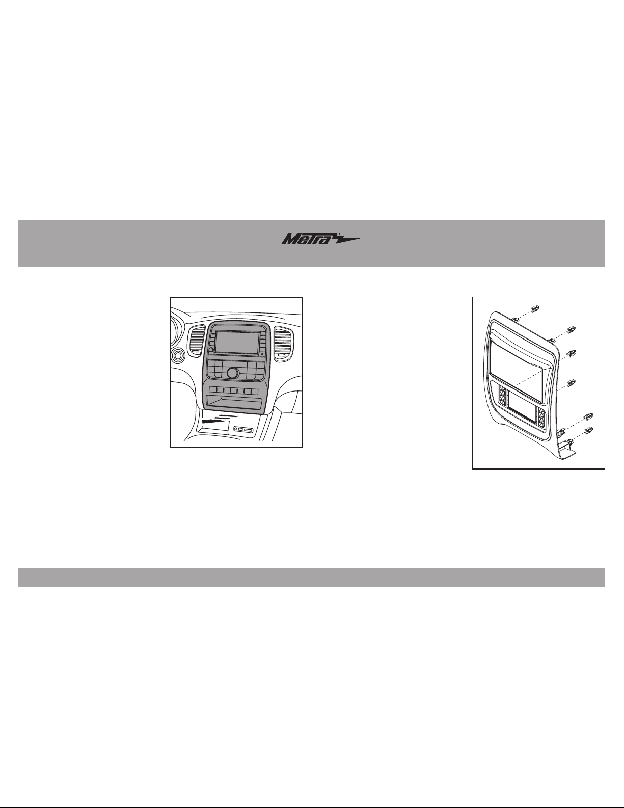
Dash Disassembly
1. Unclip and remove the radio/
climate control panel. (Figure A)
2. Remove the (4) 9/32 screws
securing the radio/display screen,
and then unplug and remove.
3. Remove the (3) 5.5mm screws
securing the black control module
in the sub-dash, and then relocate
lower to allow clearance for the
aftermarket radio.
Continue to Kit Preparation
(Figure A)
(Figure A)
To the 99-6537CH radio trim panel:
1. Attach the (6) panel clips provided.
(Figure A)
Continue to Kit Assembly
Kit Preparation
Page 3
99-6537B
3
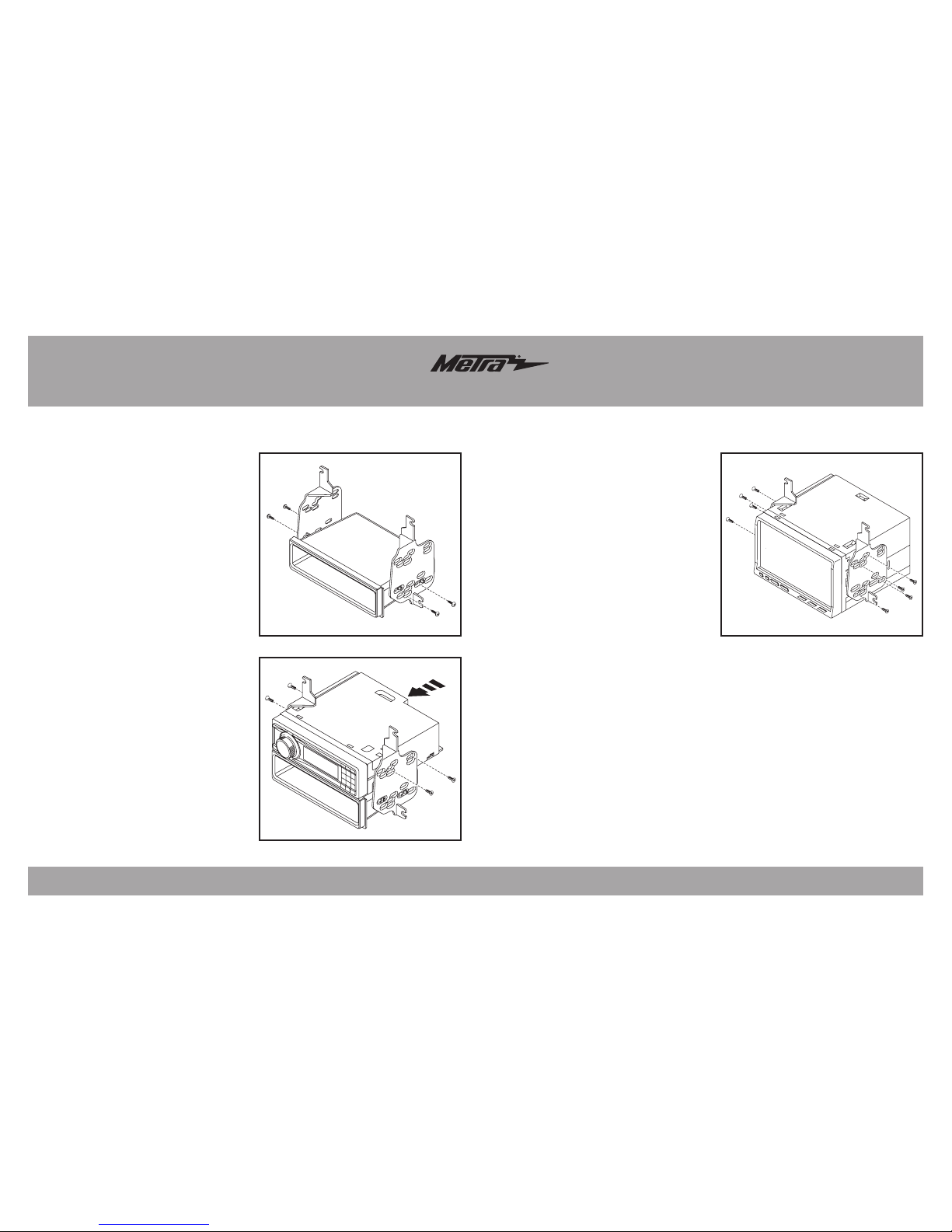
Kit Assembly
(Figure A)
(Figure B)
(Figure A)
ISO DIN radio provision with pocket
1. Attach the pocket to the radio
brackets using the (4) #8 x 3/8”
Phillips truss-head screws provided.
(Figure A)
2. Remove the metal DIN sleeve and
trim ring from the aftermarket radio.
3. Slide the radio into the bracket/
pocket assembly, and then secure it
using the screws supplied with the
radio. (Figure B)
Continue to Axxess
Interface Installation
ISO DDIN radio provision
1. Attach the brackets to the radio
using the screws supplied with
the radio. (Figure A)
Continue to Axxess
Interface Installation
Page 4

99-6537B
4
Axxess Interface Installation
• Provides accessory power (12-volt 10-amp)
• Retains R.A.P. (retained accessory power)
• Provides NAV outputs (parking brake, reverse, speed sense)
• Retains audio controls on the steering wheel
• Retains safety chimes
• Retains the factory backup camera
• Retains the factory AUX-IN jack
• Retains balance and fade*
• Micro “B” USB updatable
* Non-amplified models only.
INTERFACE FEATURES
• Wire cutter • Crimp tool • Solder gun • Tape
• Connectors (example: butt-connectors, bell caps, etc.)
TOOLS REQUIRED
• Axxess interface (built into the touchscreen display)
• 6537 harness
• 16-pin harness with stripped leads
• 4-pin harness with yellow RCA jacks
• Hazard harness
• Female 3.5mm connector with stripped leads
Connections to be made .......................................................................... 5-7
Installing the interface ............................................................................... 8
Initializing the interface ............................................................................. 8
Final assembly ............................................................................................ 8
Touchscreen display operation .............................................................9-11
Steering wheel control settings .......................................................... 12-13
INTERFACE COMPONENTS
TABLE OF CONTENTS
Page 5

99-6537B
5
Connections to be made
From the 6537 harness to the aftermarket radio:
• Connect the Black wire to the ground wire.
• Connect the Yellow wire to the battery wire.
• Connect the Gray wire to the right front positive speaker output.
• Connect the Gray/Black wire to the right front negative speaker output.
• Connect the White wire to the left front positive speaker output.
• Connect the White/Black wire to the left front negative speaker output.
• Connect the (2) 4-pin connectors together.
• If retaining the factory backup camera, connect the Yellow RCA jack to the reverse
camera input.
• If the AUX-IN jack in the dash is desired to be used, connect the Red and White RCA
jacks to the audio AUX-IN jacks of the aftermarket radio.
• Disregard the DIN jack, it will not be used in this application.
Continue to 3.5mm jack steering wheel control retention
Attention! This interface will work with models that are either non-amplified, or
amplified. Please follow the instructions carefully for your model vehicle. Failure to
do so will result in either no sound, or low sound. If you are unsure if your vehicle is
factory amplified or not, please contact your local dealership.
For models without a factory amplifier:
From the 16-pin harness with stripped leads to the aftermarket radio:
• Connect the Red wire to the accessory wire.
• If the aftermarket radio has an illumination wire, connect the Orange/White wire to it.
• Connect the Green wire to the left rear positive speaker output.
• Connect the Green/Black wire to the left rear negative speaker output.
• Connect the Purple wire to the right rear positive speaker output.
• Connect the Purple/Black wire to the right rear negative output.
• Tape off and disregard the following (6) wires, they will not be used in this application.
Blue/White, Brown, Gray, Gray/Black, White, White/Black
The following (3) wires are only for multimedia/navigation radios that require these wires.
• Connect the Blue/Pink wire to the VSS/speed sense wire.
• Connect the Green/Purple wire to the reverse wire.
• Connect the Light Green wire to the parking brake wire.
Page 6

99-6537B
6
Connections to be made
The following (3) wires are only for multimedia/navigation radios that require these wires.
• Connect the Blue/Pink wire to the VSS/speed sense wire.
• Connect the Green/Purple wire to the reverse wire.
• Connect the Light Green wire to the parking brake wire.
From the 6537 harness to the aftermarket radio:
• Connect the Black wire to the ground wire.
• Connect the Yellow wire to the battery wire.
• Tape off and disregard the following (4) wires, they will not be used in this application:
Gray, Gray/Black, White, White/Black
• Connect the (2) 4-pin connectors together.
• If retaining the factory backup camera, connect the Yellow RCA jack to the
reverse camera input.
•
If the AUX-IN jack in the dash is desired to be used, connect the Red and White RCA
jacks to the audio AUX-IN jacks of the aftermarket radio.
• Disregard the DIN jack, it will not be used in this application.
Continue to 3.5mm jack steering wheel control retention
Attention! This interface will work with models that are either non-amplified, or amplified.
Please follow the instructions carefully for your model vehicle. Failure to do so will result in
either no sound, or low sound. If you are unsure if your vehicle is factory amplified or not,
please contact your local dealership.
For models with a factory amplifier:
From the 16-pin harness with stripped leads to the aftermarket radio:
• Connect the Red wire to the accessory wire.
• Connect the Blue/White wire to the amp turn on wire. This wire must be connected to
hear sound from the factory amplifier.
• If the aftermarket radio has an illumination wire, connect the Orange/White wire to it.
• Connect the Gray wire to the right front positive speaker output.
• Connect the Gray/Black wire to the right front negative speaker output.
• Connect the White wire to the left front positive speaker output.
• Connect the White/Black wire to the left front negative speaker output.
• Connect the Green wire to the left rear positive speaker output.
• Connect the Green/Black wire to the left rear negative speaker output.
• Connect the Purple wire to the right rear positive speaker output.
• Connect the Purple/Black wire to the right rear negative output.
• Tape off and disregard the following (1) wire, it will not be used in this application: Brown
Page 7

99-6537B
7
Connections to be made (cont.)
3.5mm jack - steering wheel control retention:
The 3.5mm jack is to be used to retain audio controls on the steering wheel control.
• For the radios listed below, connect the included female 3.5mm connector with
stripped leads, to the male 3.5mm SWC jack from the 6537 harness.
Any remaining wires tape off and disregard.
• Eclipse: Connect the steering wheel control wire, normally Brown, to the
Brown/White wire of the connector. Then connect the remaining steering
wheel control wire, normally Brown/White, to the Brown wire of
the connector.
• Metra OE: Connect the steering wheel control Key 1 wire (Gray) to the
Brown wire.
• Kenwood or select JVC with a steering wheel control wire: Connect the
Blue/Yellow wire to the Brown wire.
Note: If the Kenwood radio auto detects as a JVC, manually set the radio
type to Kenwood. See the instructions under changing radio type.
• XITE: Connect the steering wheel control SWC-2 wire from the radio to the
Brown wire.
• Parrot Asteroid Smart or Tablet: Connect the 3.5mm jack into the
AX-SWC-PARROT (sold separately), and then connect the 4-pin connector from
the AX-SWC-PARROT into the radio.
Note: The radio must be updated to rev. 2.1.4 or higher software.
• Universal “2 or 3 wire” radio: Connect the steering wheel control wire,
referred to as Key-A or SWC-1, to the Brown wire of the connector. Then
connect the remaining steering wheel control wire, referred to as Key-B
or SWC-2, to the Brown/White wire of the connector. If the radio comes with
a third wire for ground, disregard this wire.
Note: After the interface has been programmed to the vehicle, refer to the
manual provided with the radio for assigning the SWC buttons. Contact the
radio manufacturer for more information.
• For all other radios: Connect the 3.5mm jack into the port on the radio designated
for an external steering wheel control interface. Refer to the manual provided with
the radio if in doubt as to where the 3.5mm jack goes to.
4-pin harness with yellow RCA jacks:
• If retaining the factory backup camera to the touchscreen display is desired,
connect the Yellow RCA jack labeled “Rearview camera”, to the Yellow RCA
jack from the 6537 harness.
• Disregard the Yellow RCA jack labeled “AUX video”, it will not be used in
this application.
Continued on the next page
Page 8

99-6537B
8
Installing the interface
It is highly advisable to read the following steps beforehand, to ensure a clear understanding of
what is to be expected. The following steps must be done in the order that they are numbered.
With the vehicle completely off:
Touchscreen display
1. Connect the 16-pin harness with stripped leads into port “B” in the touchscreen display.
2. Connect the 6537 harness to the wiring harnesses in the vehicle. Then insert the 6537
harness into port “A” in the touchscreen display. But do not install this harness until exactly
before step 1 of “Initializing the Interface”. This is a timed process
3. Connect the 4-pin harness with yellow RCA jacks into port “C” in the touchscreen display.
4. Connect the hazard harness into port “D” in the touchscreen display, and then to the wiring
harness in the vehicle.
5. Disregard port “E”, it will not be used in this application.
6. Port “F” is an update port for future firmware upgrades.
7. Locate the factory antenna connector in the dash and complete all necessary connections
to the radio. Metra recommends using the proper mating adapter from Metra.
A
B
C
E
F
D
Initializing the interface
Attention! If the interface loses power for any reason, the following steps
will need to be performed again.
1.
Refer to step 2 of “Installing the interface”.
2. Press the push-to-start button to start the vehicle.
3. Program the kit:
a. Once the touchscreen display loads up, select the vehicle type; “Dodge Durango”.
b. Wait until the radio comes on, and the touchscreen display shows
“SWC Configured”. This process may take up to 3 minutes.
Note: If the touchscreen display does not load up, or the radio doesn’t come on within 3
minutes, and/or the touchscreen display does not show “SWC Configured”, turn the vehicle
off and disconnect the 6537 harnesses from port “A” in the touchscreen display. Check all
the connections, reconnect the harness into the touchscreen display, and then try again.
4. Test all functions of the installation for proper operation, before reassembling the dash.
Note: The clock and compass in the driver’s information center will no longer be functional.
Final assembly
2. Secure the completed assembly into the upper dash using the factory hardware.
3. Snap the radio trim panel with touchscreen display over the completed assembly, and
then reassemble the dash in reverse order of disassembly.
Page 9

99-6537B
9
Touchscreen display operation
• This is the HVAC control screen which will be displayed on the touchscreen display.
This is considered the Main Menu screen.
•
The upper left tab with (3) arrows will take you to the Heated/Cooled Seats* screen,
Heated Steering* screen, Mirror Dimming* screen, and also to the screen where the
“hard buttons” that were on the factory radio panel are now placed:
ECO/ESC/PARK-SENSE/SPORT/STOP-START*
•
The upper right tab with a gear icon will take you to the Configuration Settings screen.
• The climate controls will function in the same manner that they did with the factory
climate controls.
• For models with rear climate controls, the button labeled “REAR” will take you to the
rear climate control menu.
* If applicable.
• This is the Heated/Cooled Seats, Heated Steering, and Mirror Dimming control screen
which will be displayed on the touchscreen display.
• The upper left-middle tab with a home icon will take you back to the Main Menu screen.
• The upper right-middle tab with a gear icon will take you to the
Configuration Settings screen.
•
The upper right tab with a car icon will take you to the screen where the “hard buttons”
that were on the factory radio panel are now placed:
ECO/ESC/PARK-SENSE/SPORT/STOP-START
HVAC Control screen Heated seats screen
Page 10

99-6537B
10
Touchscreen display operation
• This is the screen where you can access the “hard buttons” that were on the
factory radio panel: ECO/ESC/PARK-SENSE/SPORT/STOP-START
• The upper left tab with (3) arrows will take you back to the
Heated/Cooled Seats screen.
• The upper middle tab with a home icon will take you to the Main Menu screen.
• The upper right tab with a gear icon will take you to the
Configuration Settings screen.
ECO/ESC/PARK-SENSE/SPORT/STOP-START screen
• ECO – Fuel Economy Mode
• ESC – Electronic Stability Control
• PARK-SENSE – ParkSense Rear Park Assist System
• SPORT – Sport Mode
• STOP-START – Stop/Start System
Page 11

99-6537B
11
• Backlight
• Four slide bars control the color of the buttons and the back-light intensity:
Red / Green / Blue / Backlight
• Backup Camera
• Enable – Enables the backup camera image to the touchscreen display
• Disable – Disables the backup camera image to the touchscreen display
(default)
Configuration Settings screen
• Steering Wheel Controls
• Remap Buttons – For remapping the steering wheel control buttons
• Dual Assign – For dual assigning the steering wheel control buttons
(long button press)
• Select Radio – For auto detecting the radio, or changing the radio type
• System Configuration
• Firmware version
Touchscreen calibration:
• Press and hold the upper two soft buttons on either side of the touchscreen
for 10 seconds.
• A screen will pop up asking for you to press the target in the screen.
• After pressing the target with your finger, the calibration process will be
complete, and the screen will disappear.
Touchscreen display operation (cont.)
Page 12

99-6537B
12
Steering wheel control settings
Select Radio screen
* Note: If the interface shows an Alpine radio, and you do not have an Alpine
radio, that means the interface does not detect a radio connected it, i.e., an open
connection. Verify that the 3.5mm jack is connected to the correct steering wheel
jack/wire in the radio.
** Note: The AX-SWC-PARROT is required (sold separately). Also, the Parrot
radio must be updated to rev. 2.1.4.
† Note: If you have a Clarion radio and the steering wheel controls do not work,
change the radio type to the other Clarion radio type; same for Eclipse.
‡ Note: If you have a Kenwood radio and the touchscreen display shows a JVC
radio, change the radio type to Kenwood.
Continued on the next page
Eclipse (Type 1) †
Kenwood ‡
Clarion (Type 1) †
Sony / Dual
JVC
Pioneer/Jensen
Alpine *
Visteon
Valor
Clarion (Type 2) †
Metra OE
Eclipse (Type 2) †
LG
• To show which brand radio is “auto detected” to the interface, press the
“Autodetect” button. The radio detected will have a filled in circle. If the
incorrect radio is shown, select the proper radio.
• Following is a list of radio manufacturers that the interface presently
acknowledges. Others may be added at a later date. Universal “2 or 3 wire”
radios can show up as any of these radio manufacturers.
Parrot **
XITE
Philips
JBL
Page 13

99-6537B
13
Steering wheel control settings (cont.)
Remap Button screen Dual Assign screen
• The interface has the ability to change the button assignment for the steering
wheel control audio buttons, except Volume-Up and Volume-Down. Follow the
prompts on the touchscreen display to remap the steering wheel control audio
button(s) to your liking.
Note: The aftermarket radio may not have all of these commands. Please refer
to the manual provided with the radio, or contact the radio manufacturer, for
specific commands recognized by that particular radio.
• The interface has the capability to assign two functions to a single button,
except Volume-Up and Volume-Down. Follow the prompts on the touchscreen
display to program the button(s) to your liking.
Note: Seek-Up and Seek-Down come programmed as Preset-Up and
Preset-Down for a long button press.
 Loading...