

Page 1

installation instructions for Part 99-6507
APPLICATIONS
DODGE
Caliber 2007-2008
Charger 2005-2007
Dakota 2005-2007
Durango 2004-2007
Magnum 2005-2007
Ram 2006-2008
Ram 2500/3500 2009
MITSUBISHI
Raider 2006-2007
CHRYSLER
300 2005-2007
Aspen 2007
PT Cruiser 2006-2009
JEEP
Commander 2006-2007
Compass 2007-2008
Grand Cherokee 2005-2007
Patriot 2007-2008
NOTE: NON NAV MODELS ONLY
99-6507
KIT FEATURES
• DIN Radio Provision with Pocket
• ISO DIN Radio Provision with Pocket
KIT COMPONENTS
A) Radio Housing • B) ISO Snap-In Brackets • C) Trim Plates (upper & lower)
Upper Trim Plate
WIRING AND ANTENNA CONNECTIONS (Sold Separately)
Harness:
A
C
Lower Trim Plate
• CHTO-01 - Chrysler amp interface harness 2004-up
• XSVI-6502-NAV - Chrysler R.A.P. harness 2004-up
Antenna Adapter:
• 40-CR10 - Chrysler antenna adapter 2002-up
B
TOOLS REQUIRED:
Phillips Screwdriver • Socket Wrench •
Small Flat Blade Screwdriver or
Panel Removal Tool
1-800-221-0932 www.metraonline.com
© COPYRIGHT 2004-2010 METRA ELECTRONICS CORPORATION
Page 2

99-6507
KNOWLEDGE IS POWER
Enhance your installation and fabrication skills by
enrolling in the most recognized and respected
mobile electronics school in our industry.
Log onto www.installerinstitute.com or call
800-354-6782 for more information and take
steps toward a better tomorrow.
taBlE of contEnts
Dash Disassembly
- Chrysler Aspen 2007 . . . . . . . . . . . . . . . . . . . . . . . . . . . . . . . . . . . . . . . . . . . . . 1
- Dodge Dakota 2005-2007 . . . . . . . . . . . . . . . . . . . . . . . . . . . . . . . . . . . . . . . . . 1
- Dodge Durango 2004-2007 . . . . . . . . . . . . . . . . . . . . . . . . . . . . . . . . . . . . . . . 1
- Dodge Charger 2005-2007 . . . . . . . . . . . . . . . . . . . . . . . . . . . . . . . . . . . . . . . . 2
- Dodge Magnum 2005-2007 . . . . . . . . . . . . . . . . . . . . . . . . . . . . . . . . . . . . . . . 2
- Chrysler 300 2005-2007 . . . . . . . . . . . . . . . . . . . . . . . . . . . . . . . . . . . . . . . . . . . 3
- Dodge Ram 2006-2008 (Without Center Console) . . . . . . . . . . . . . . . . . . . . . . 4
- Dodge Ram 2006-2008 (With Mini Center Console) . . . . . . . . . . . . . . . . . . . . . 5
- Dodge Ram 2006-2008 (With Full Center Console) . . . . . . . . . . . . . . . . . . . . . 6
- Dodge Caliber 2007-2008 . . . . . . . . . . . . . . . . . . . . . . . . . . . . . . . . . . . . . . 7
- Jeep Compass 2007-2008 . . . . . . . . . . . . . . . . . . . . . . . . . . . . . . . . . . . . . . 7
- Jeep Patriot 2007-2008 . . . . . . . . . . . . . . . . . . . . . . . . . . . . . . . . . . . . . . . . 7
- Jeep Grand Cherokee 2005-2007 . . . . . . . . . . . . . . . . . . . . . . . . . . . . . . . . . . 8
- Jeep Commander 2006-2007 . . . . . . . . . . . . . . . . . . . . . . . . . . . . . . . . . . . . . . 9
- Chrysler PT Cruiser 2006-2009 . . . . . . . . . . . . . . . . . . . . . . . . . . . . . . . . . . .10
- Mitsubishi Raider 2006-2007 . . . . . . . . . . . . . . . . . . . . . . . . . . . . . . . . . . . 11
Kit Assembly
- DIN Radio Provision with Pocket . . . . . . . . . . . . . . . . . . . . . . . . . . . . . . . . . . .12
- ISO Radio Provision with Pocket . . . . . . . . . . . . . . . . . . . . . . . . . . . . . . . . . . . 13
Final Assembly
. . . . . . . . . . . . . . . . . . . . . . . . . . . . . . . . . . . . . . . . . . . . . . . . . .14
Page 3

99-6507
cHrYslEr asPEn 2007
DoDgE Dakota 2005-2007
DoDgE Durango 2004-2007
Disconnect the negative battery terminal
1
to prevent an accidental short circuit.
Remove (2) 7MM screws from the inside
2
of the pocket facing upward. (
Figure A)
DasH DisassEMBlY
A
Unclip and remove the entire trim panel
3
surrounding the radio and climate controls.
Figure B)
(
Remove (4) 7MM screws securing radio.
4
Unplug and remove radio.(
Continue to kit assembly.
5
Figure C)
B
C
1
Page 4

99-6507
DoDgE cHargEr 2005-2007
DoDgE MagnuM 2005-2007
Disconnect the negative battery terminal
1
to prevent an accidental short circuit.
Unclip and remove entire panel surrounding
2
radio and climate controls, including a/c
vents. (
Figure A)
DasH DisassEMBlY
A
Remove (4) 7MM screws securing radio.
3
Unplug and remove radio. (
Continue to kit assembly.
4
Figure B)
B
2
Page 5

99-6507
cHrYslEr 300 2005-2007
Disconnect the negative battery terminal
1
to prevent an accidental short circuit.
Unclip and remove entire panel surround-
2
ing radio and climate controls, including
a/c vents and clock. (
Remove (4) 7MM screws securing radio.
3
Unplug and remove radio. (
Figure A)
Figure B)
DasH DisassEMBlY
A
B
Continue to kit assembly.
4
3
Page 6

99-6507
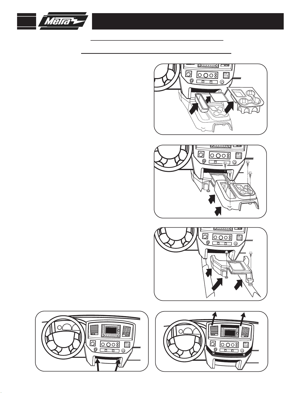
DoDgE raM 2006-2008
witHout cEntEr consolE
Disconnect the negative battery terminal
1
to prevent an accidental short circuit.
Open cup holder and remove (2) Phillips
2
screws facing up on front edge of
radio/climate control panel. (
Figure A)
DasH DisassEMBlY
A
Unclip and remove entire panel sur-
3
rounding radio and climate controls,
including a/c vents. (
Remove (4) 7MM screws securing radio.
4
Unplug and remove radio.
Continue to kit assembly.
5
Figure B)
B
4
Page 7
99-6507
DasH DisassEMBlY
DoDgE raM 2006-2008
witH Mini cEntEr consolE
Disconnect the negative battery terminal
1
to prevent an accidental short circuit.
If vehicle has floor shifter, remove shifter
2
knob.
Remove center console inserts, if present.
3
Figure A)
(
Remove screws securing the rear center
4
console to the floor panel. Lift up on the
rear center console to clear the gear shift
lever, if present. (
Remove screws securing the front center
5
console to the floor panel. Unclip and
remove the front center console.
Figure C)
(
Remove two phillips head screws at bottom
6
of dash. Unsnap and remove lower panel.
Figure B)
A
B
Remove (2) Phillips screws facing up on
7
front edge of radio/climate control panel.
Figure D)
(
Unclip and remove entire panel sur-
8
rounding radio and climate controls,
including a/c vents. (
Remove (4) 7MM screws securing radio
9
to dash and remove radio.
10
Continue to kit assembly.
Figure E)
D
C
E
5
Page 8

99-6507
DoDgE raM 2006-2008
witH full cEntEr consolE
Disconnect the negative battery terminal
1
to prevent an accidental short circuit.
If vehicle has floor shifter, remove shifter
2
knob.
Unsnap and remove console front top
3
cover (closest to the dash). (
Figure A)
DasH DisassEMBlY
A
Remove two 8 mm screws from under
4
console cover (previously removed).
Remove front section of console.
Figure B)
(
Loosen two 8 mm screws at bottom of
5
dash. Unsnap lower panel.
Remove (2) Phillips screws facing up on
6
front edge of radio/climate control panel.
Figure C)
(
Unclip and remove entire panel surrounding
7
radio and climate controls, including a/c
vents. (
Figure D)
B
C
Remove (4) 7MM screws securing radio
8
to dash and remove radio.
Continue to kit assembly.
9
D
6
Page 9

99-6507
123 4
5
6
L
D
L
D
N
R
P
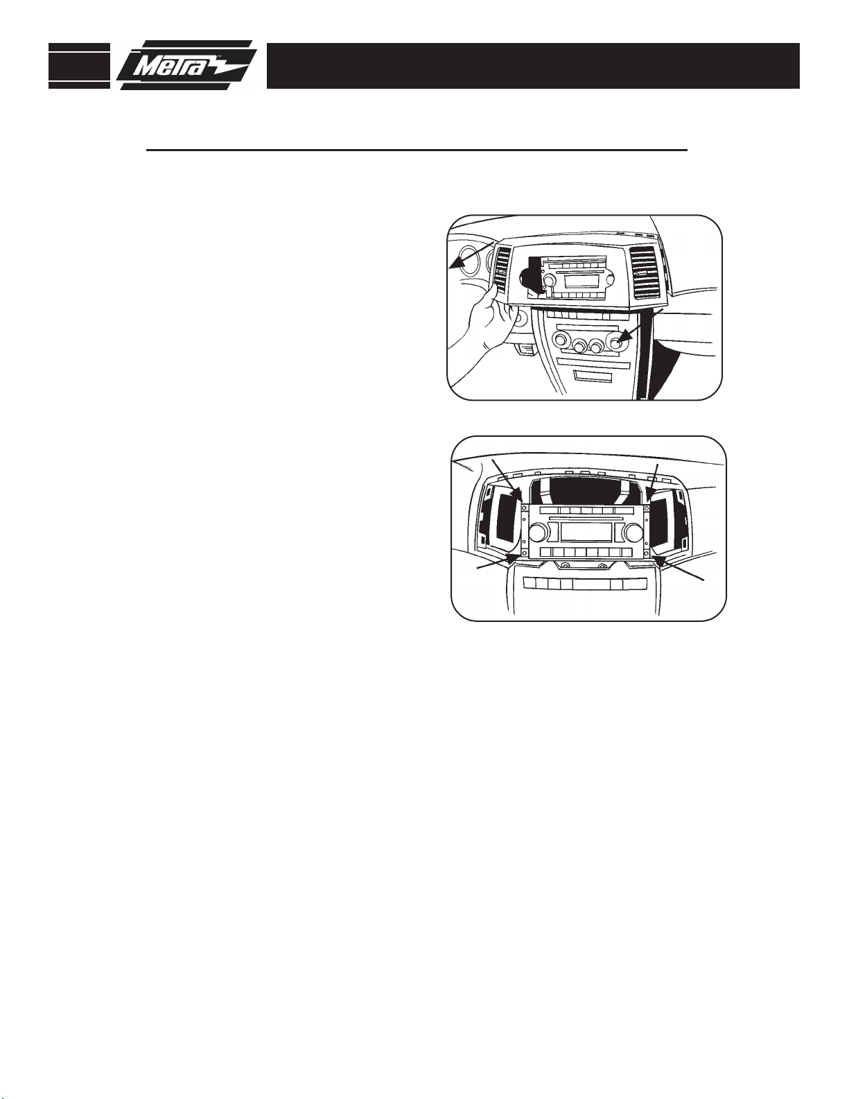
DoDgE caliBEr 2007-2008
JEEP coMPass 2007-2008
JEEP Patriot 2007-2008
Disconnect the negative battery terminal
1
to prevent an accidental short circuit.
Unsnap and move shifter trim to the side.
2
Figure A)
(
(Compass and Patriot only) Unspap and
3
remove top center dash panel above AC
vents.
Unsnap center dash trim panel (do not
4
remove until climate controls are
removed). (
Figure A)
DasH DisassEMBlY
A
5
6
7
Remove (4) Phillips screws holding
climate control panel to backside of
the center dash panel.
Remove (4) 7MM screws securing radio.
Unplug and remove radio.
Continue to kit assembly.
7
Page 10
99-6507
DasH DisassEMBlY
JEEP granD cHErokEE 2005-2007
A
Disconnect the negative battery terminal
1
to prevent an accidental short circuit.
Unsnap and remove panel from around
2
radio including the vent on each side.
Figure A)
(
Remove (4) 7MM screws securing radio.
3
Unplug and remove radio. (
Continue to kit assembly.
4
Figure B)
B
8
Page 11

99-6507
4 screws 4 screws 4 screws
4 screws
JEEP coMManDEr 2006-2007
Disconnect the negative battery terminal
1
to prevent an accidental short circuit.
Remove the (16) screws securing the
2
radio trim panel. (
A
Figure A)
DasH DisassEMBlY
Unclip and remove the entire radio trim
3
panel. (
Figure B)
B
Remove (4) 7MM screws securing radio. Unplug and remove radio.
4
Continue to kit assembly.
5
9
Page 12
99-6507
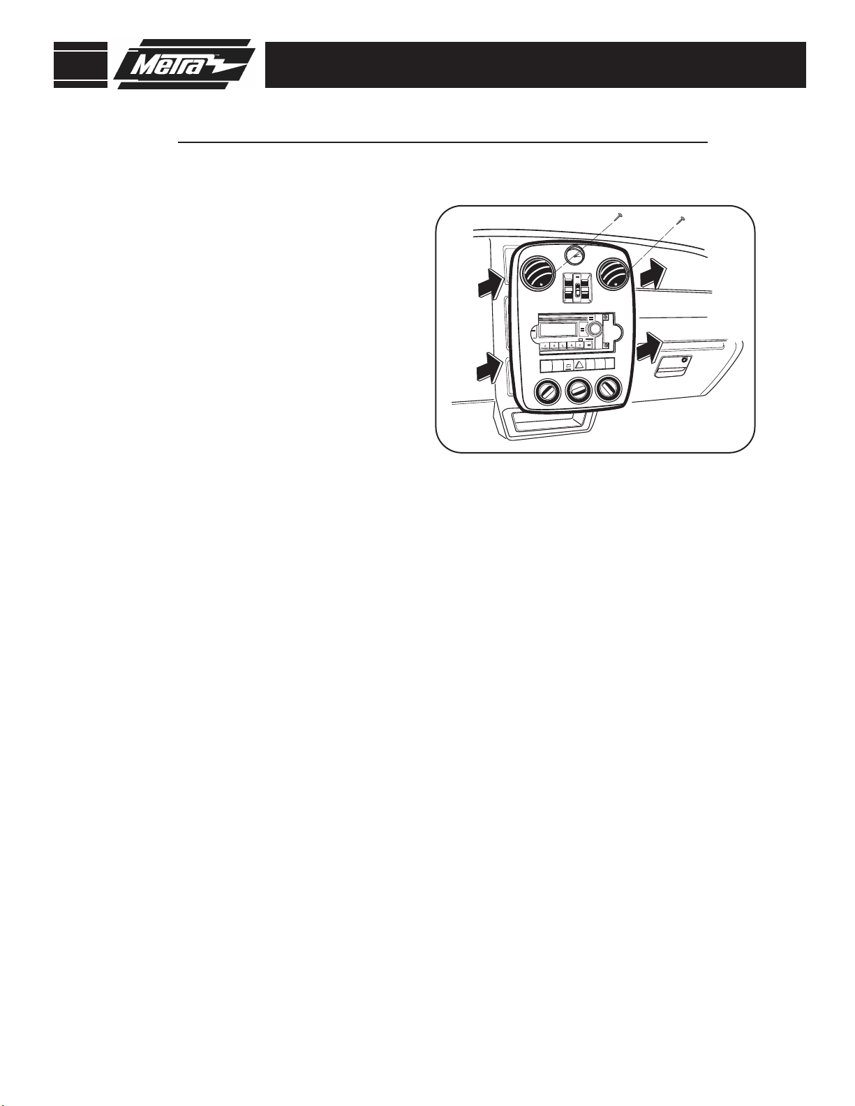
cHrYslEr Pt cruisEr 2006-2009
Disconnect the negative battery terminal
1
to prevent an accidental short circuit.
Remove (2) screws from inside air vents
2
on center dash panel. (
Unsnap center dash panel (do not remove
3
until climate controls are removed).
Figure A)
(
Remove (4) Phillips screws holding climate
4
control panel to backside of the center
dash panel.
Figure A)
DasH DisassEMBlY
A
Remove (4) Phillips screws holding climate
5
control panel to backside of the center
dash panel.
Remove (4) 7MM screws securing radio.
6
Unplug and remove radio.
Continue to kit assembly.
7
10
Page 13
99-6507
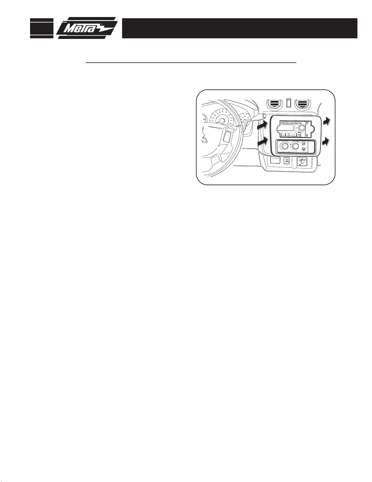
MitsuBisHi raiDEr 2006-2007
Disconnect the negative battery terminal
1
to prevent an accidental short circuit.
Unsnap and remove center dash panel.
2
Figure A)
(
Remove (4) 7MM screws securing radio.
3
Unplug and remove radio.
Continue to kit assembly.
4
DasH DisassEMBlY
A
11
Page 14
99-6507
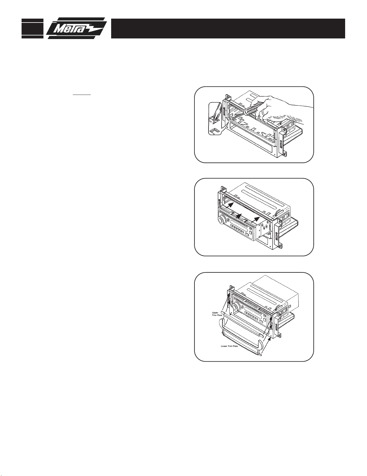
kit assEMBlY
Din raDio Provision witH PockEt
A
NOTE:
aftermarket radio’s trim ring if
equipped.
Slide the DIN cage into the Radio
1
Housing and secure by bending
the metal locking tabs down.
(
Slide the after-market head unit into
2
the cage and secure. (
You will need to remove the
Figure A)
Figure B)
B
Using the alignment pins on the
3
trim plates & the corresponding
holes in the housing, attach the
upper trim plate and the lower trim
plate supplied with the kit.
Figure C
Continue to Final Assembly.
4
C
12
Page 15

99-6507
kit assEMBlY
iso raDio Provision witH PockEt
NOTE:
aftermarket radio’s trim ring if
equipped.
Mount the ISO Brackets to the
1
radio using the screws supplied
with the radio.
Slide the radio into the opening
2
until it snaps into place.
Using the alignment pins on the
3
trim plates & the corresponding
holes in the housing, attach the
upper trim plate and the lower trim
plate supplied with the kit.
You will need to remove the
Figure A
A
B
Figure B
Figure B
Continue to Final Assembly.
4
13
Page 16

99-6507
final assEMBlY
final assEMBlY
A
B
C
D
1
2
3
4
Locate the factory wiring harness in the dash. Metra recommends using the
proper mating adapter and making connections as shown.
(Isolate and individually tape off the ends of any unused wires to prevent
electrical short circuit.)
Secure the kit into the sub dash using the (4) 7mm screws that secured
the factory radio.
Re-connect the negative battery terminal and test the unit for proper operation.
Reassemble radio and dash assemblies in reverse order of disassembly.
FINAL WIRING CONNECTIONS
A) Strip wire ends back 1/2"
B) Twist ends together
C) Solder
D) Tape
Make wiring connections using the EIA color code chart shown below and the instructions included with the head
unit. Metra recommends making connections as shown below; Strip, Splice, Solder, Tape. Isolate and individually
tape off ends of any unused wires to prevent electrical short circuit.
METRA / EIA WIRING CODE
12V Ignition / Acc . . . Red
12V Batt / Memory . . Yellow
Ground . . . . . . . . . . . Black*
Power Antenna . . . . . Blue
Amp Turn-On . . . . . . Blue / White
Amp Ground . . . . . . . Black / White
Illumination. . . . . . . . Orange
*NOTE:
When Black a wire is not present, ground radio to vehicle chassis.
All colors may not be present on all leads due to manufacturer’s specifications.
Dimmer . . . . . . . . . . Orange / White
Right Front (+) . . . . . White
Left Front (-) . . . . . . . White / Black
Right Rear (+). . . . . . Violet
Right Rear (-) . . . . . . Violet / Black
Left Rear (+). . . . . . . Green
Left Rear (-) . . . . . . . Green / Black
1-800-221-0932 www.metraonline.com
REV. 06/30/10 © COPYRIGHT 2004-2010 METRA ELECTRONICS CORPORATION INST99-6507
 Loading...