

Page 1
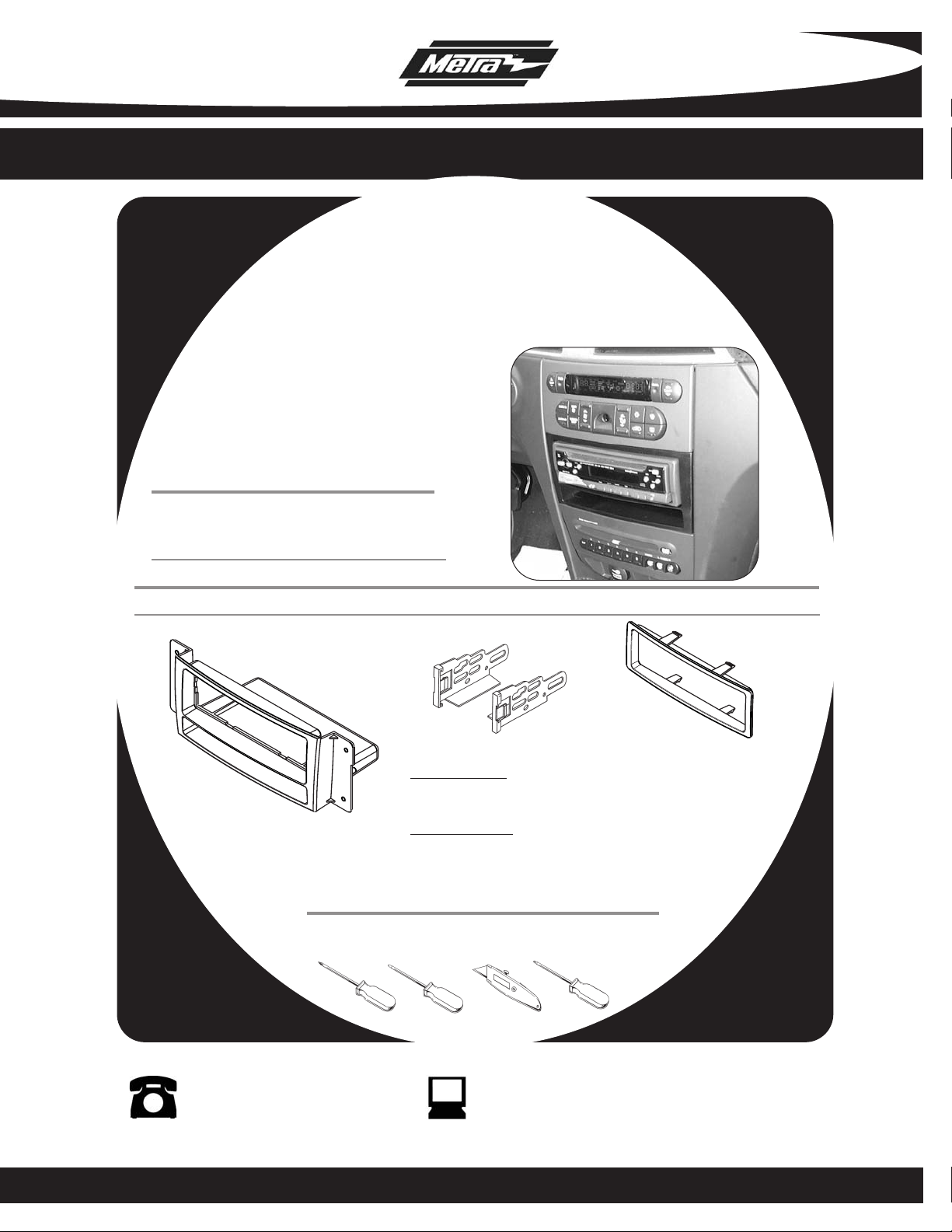
INSTALLATION INSTRUCTIONS FOR PART 99-6506
APPLICATIONS
Chrysler Pacifica
2004-2008
99-6506
KIT FEATURES
• DIN Head unit provision with pocket
• ISO DIN Head unit provision with pocket
KIT COMPONENTS
A) Radio Housing • B) ISO Brackets • C) Trim Plate
B
C
WIRING AND ANTENNA CONNECTIONS (Sold Separately)
e harnesses:
Wir
A
Phillips Screwdriver • Small Flat Blade Screwdriver • Cutting Tool • T-15 Torx Driver
• CHTO-02 Chrysler/Dodge amplified interface 2002-up
• 70-6506 Chrysler/Dodge amplified bypass harness 2002-up
Antenna adapter:
• 40-CR10 - Chrysler/Dodge antenna adapter 2002-up
TOOLS REQUIRED:
1-800-221-0932 www.metraonline.com
© COPYRIGHT 2004-2009 METRA ELECTRONICS CORPORATION
Page 2

99-6506
K
NOWLEDGE IS POWER
Enhance your installation and fabrication skills by
enrolling in the most recognized and respected
mobile electronics school in our industry.
Log onto www.installerinstitute.com or call
800-354-6782 for more information and take steps
toward a better tomorrow.
TABLE OF CONTENTS
Dash Disassembly
Chrysler Pacifica 2004-2008 . . . . . . . . . . . . . . . . . . . . . . . . . . . 1
Kit Assembly
Din Head Unit Provision. . . . . . . . . . . . . . . . . . . . . . . . . . . . . . . . 2
ISO Din Head Unit Provision. . . . . . . . . . . . . . . . . . . . . . . . . . . . . 3
Final
Assembly . . . . . . . . . . . . . . . . . . . . . . . . . . . . . . . . . . . . . . . 4
Page 3
99-6506
P
R
N
D
A
UTOSTICK
P
R
N
D
A
UTOSTICK
POWER
OUTLET
POWER
OUTLET
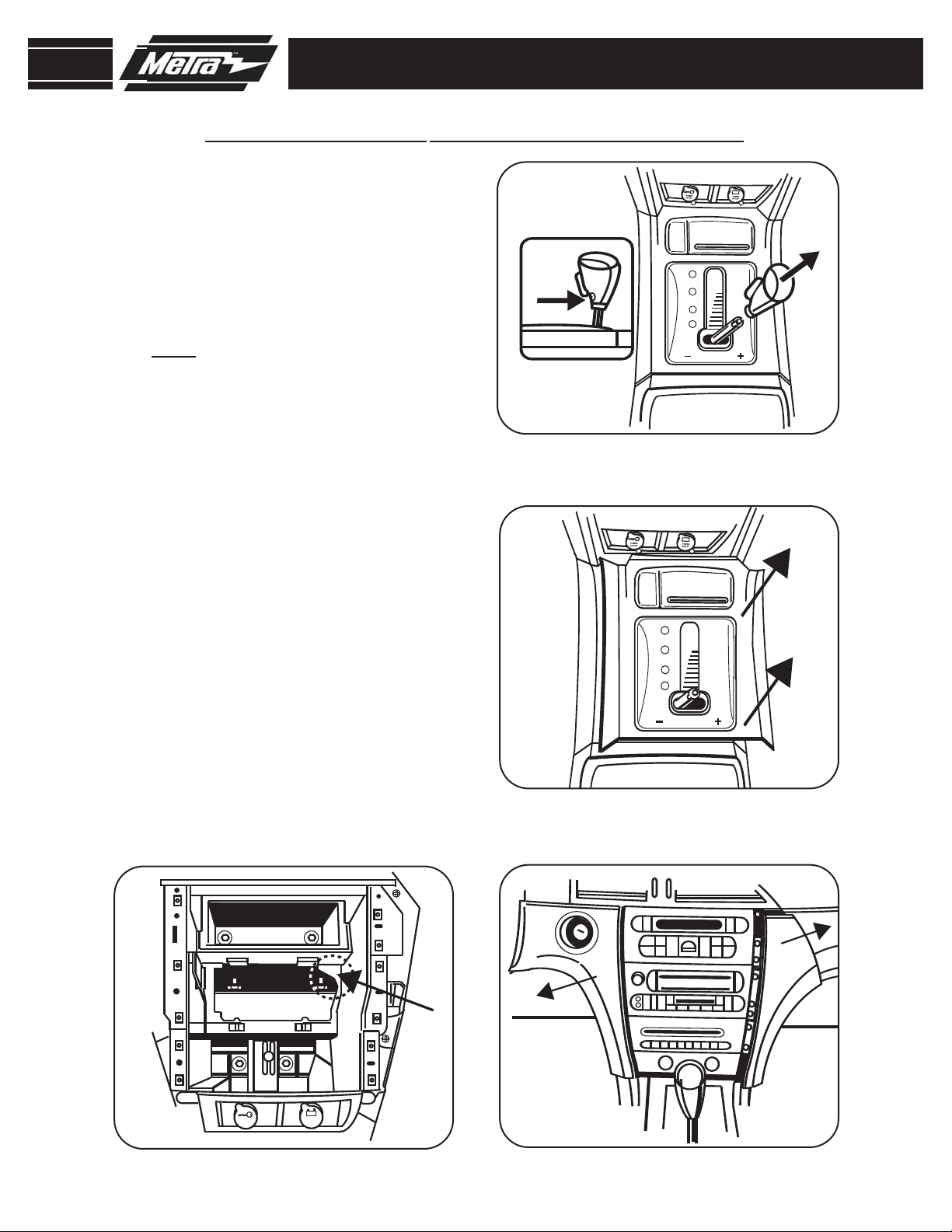
CHRYSLER PACIFICA 2004-2008
Disconnect the negative battery
1
terminal to prevent an accidental
short circuit.
2
Loosen (1) T-15 Torx screw from the
front side of shift knob and pull up to
remove.
NOTE:
release lever on shift knob just turn
counter-clockwise to remove.
Unsnap floor console trim around the
3
shifter. Unplug harness to console
trim and remove trim.
(Figure A)
For models equipped with no
(Figure B)
DASH DISASSEMBLY
A
Unsnap and remove ignition key
4
trimring.
Unsnap and remove the dash trim
5
panels from each side of the Radio/
Climate Controls.
Remove (4) Phillips screws to
6
(Figure C)
remove radio.
Note: When DIN mounting a radio a
piece of plastic in the dash cavity
may have to be removed for radio
depth clearance (
D
Figure D
).
B
C
1
Page 4

99-6506
POWER
OUTLET
POWER
OUTLET
DIN HEAD UNIT PROVISION
Slide the DIN cage into the Radio
1
Housing and secure by bending the
metal locking tabs outward.
Slide the aftermarket head unit into
2
the cage and secure. Snap the
Trimplate into the Radio Housing.
Figure B)
(
KIT ASSEMBLY
A
(Figure A)
Note: When DIN mounting a radio a
piece of plastic in the dash cavity may
have to be removed for radio depth
clearance. (
Figure C)
B
C
2
Page 5

99-6506
ISO DIN HEAD UNIT PROVISION
Mount the ISO Brackets to the head
1
unit with the screws supplied with
the unit.
Slide the head unit into the radio
2
opening until the side clips engage.
Snap the Trim Plate into the Radio
Housing.
(Figure A)
(Figure B)
KIT ASSEMBLY
A
B
3
Page 6

99-6506
FINAL ASSEMBLY
FINAL ASSEMBLY
Locate the factory wiring harness in the dash and make the connection as shown.
1
Metra recomends using the proper mating adapter and making the connections as
shown. (Isolate and individually tape off the ends of any unused wires to prevent
electrical short circuit.)
Re-connect the negative battery terminal and test the unit for proper operation.
2
3
Reassemble radio and dash assemblies in reverse order of disassembly.
FINAL WIRING CONNECTIONS
Make wiring connections using the EIA color code chart shown below and the instructions included with the head
unit. Metra recommends making connections as shown below; Strip, Splice, Solder, Tape. Isolate and individually
tape off ends of any unused wires to prevent electrical short circuit.
A
B
C
D
A) Strip wire ends back 1/2"
B) Twist ends together
C) Solder
D) Tape
METRA / EIA WIRING CODE
12V Ignition / Acc . . . Red
12V Batt / Memory . . Yellow
Ground . . . . . . . . . . . Black*
Power Antenna . . . . . Blue
Amp Turn-On . . . . . . Blue / White
Amp Ground . . . . . . . Black / White
Illumination. . . . . . . . Orange
Right Front (+) . . . . . Gray
Right Front (-) . . . . . . Gray / Black
Left Front (+) . . . . . . White
Left Front (-) . . . . . . . White / Black
Right Rear (+). . . . . . Violet
Right Rear (-) . . . . . . Violet / Black
Left Rear (+). . . . . . . Green
Dimmer . . . . . . . . . . Orange / White
*NOTE: When Black a wire is not present, ground radio to vehicle chassis.
All colors may not be present on all leads due to manufacturer’s specifications.
Left Rear (-) . . . . . . . Green / Black
4
Page 7

95-6506
NOTES
5
Page 8

99-6506 INSTRUCTIONS
1-800-221-0932 www.metraonline.com
REV. 04/20/09
© COPYRIGHT 2004-2009 METRA ELECTRONICS CORPORATION
INST99-6506
 Loading...