

Page 1
INSTALLATION INSTRUCTIONS FOR PART 99-6505
APPLICATIONS
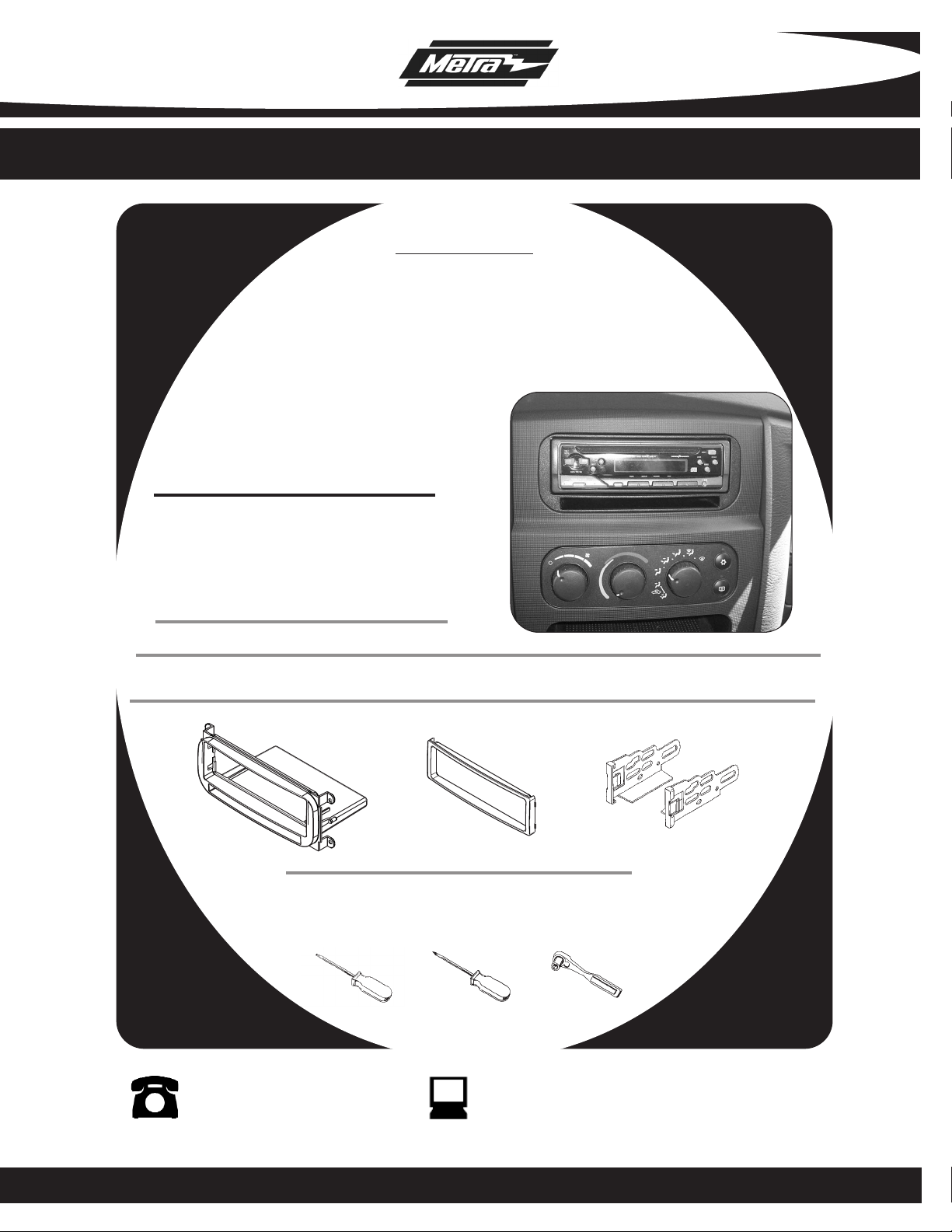
Chrysler Multi Kit
99-6505
KIT FEATURES
• DIN Head Unit Provision with pocket
• ISO DIN Head Unit Provision with pocket
KIT COMPONENTS
A) Radio Housing • B) ISO Trim Plate • C) ISO Snap in Brackets
A
A) T orx # 20 • B) Phillips Screwdriver • C) Socket Wrench
B
TOOLS REQUIRED:
C
1-800-221-0932 www.metraonline.com
© COPYRIGHT 2010 METRA ELECTRONICS CORPORATION
Page 2

99-6505
TABLE OF CONTENTS
Dash Disassembly
Chrysler 300M 1999-2004/Concorde 1998-2004/
Chrysler LHS 1998-2001/ Dodge Intrepid 1998-2004.............................1
Chrysler PT Cruiser. 2001-2005...............................................................1
Chrysler Sebring/Dodge Stratus 2001-2006.......................................... 2
Chrysler Town & Country/Voyager 2000-03/Dodge Caravan 2001-07 ..2
Dodge Neon 2000-2006/Plymouth Neon 2000-2001............................. 3
Dodge Ram 2002-2005........................................................................... 3
Dodge Viper 2003-2009 .......................................................................... 6
Jeep Grand Cherokee 1999-2004............................................................4
Dodge Dakota 2001-2004/Durango 2001-2003..................................... 4
Jeep Liberty 2002-2007...........................................................................5
Jeep Wrangler 2003-2006.......................................................................5
Kit Assembly
DIN Head Unit Provision.......................................................................... 7
ISO DIN Head Unit Provision................................................................... 8
Final Assembly
....................................................................................... 9
Page 3
99-6505
DASH DISASSEMBLY
CHRYSLER 300M 1999-2004/CONCORDE 1998-2004
CHRYSLER LHS 1998-2001/DODGE INTREPID 1998-2004
Disconnect the negative battery
1
terminal to prevent an accidental
short circuit.
2
Remove the ashtray by pressing
down on the inner spring clip.
(Concorde only)
Unclip gear shifter trim panel and
3
slide trim panel toward the rear of
the vehicle.
Unclip dash trim panel and discon-
4
nect the wire to the trim panel.
Remove (4) Phillips head screws
5
securing the radio. Disconnect and
remove the radio. Skip to kit assembly page.
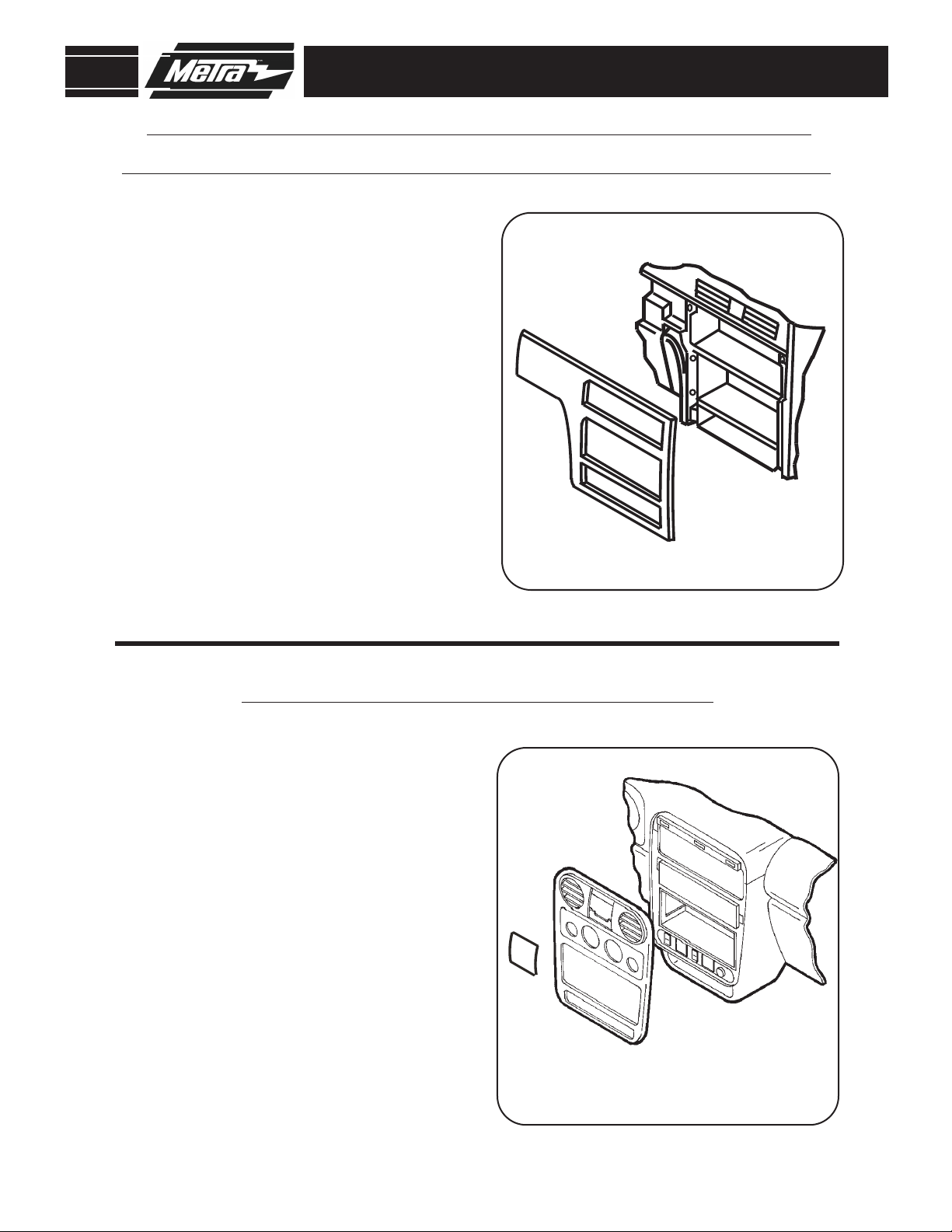
CHRYSLER PT CRUISER 2001-2005
Disconnect the negative battery
1
terminal to prevent an accidental
short circuit.
Unclip power window control panel.
2
Disconnect and remove panel.
3
Pull off climate control knobs.
4
Unclip and remove the dash trim
panel.
5
Remove (4) Phillips head screws
securing the radio. Disconnect and
remove the radio. Skip to kit assembly page.
1
Page 4
99-6505
CHRYSLER SEBRING
DODGE STRATUS 2001-2006
Disconnect the negative battery
1
terminal to prevent an accidental
short circuit.
2
Remove (2) Phillips head screws
from under the climate controls.
Unclip and remove radio trim panel.
3
4
Remove (4) Phillips head screws
securing the radio. Disconnect and
remove the radio. Skip to kit assembly page.
DASH DISASSEMBLY
CHRYSLER TOWN & COUNTRYDODGE CARAVAN 2001-2007
CHRYSLER VOYAGER 2000-2003
Disconnect the negative battery
1
terminal to prevent an accidental
short circuit.
2
Open cup holder. Unclip and remove
trim above cup holder.
Remove (2) Phillips head screws
3
from above cup holder.
4
Unclip and remove the dash trim
panel.
5
Remove (4) Phillips head screws
securing the radio. Disconnect and
remove the radio. Skip to kit assembly page.
2
Page 5

99-6505
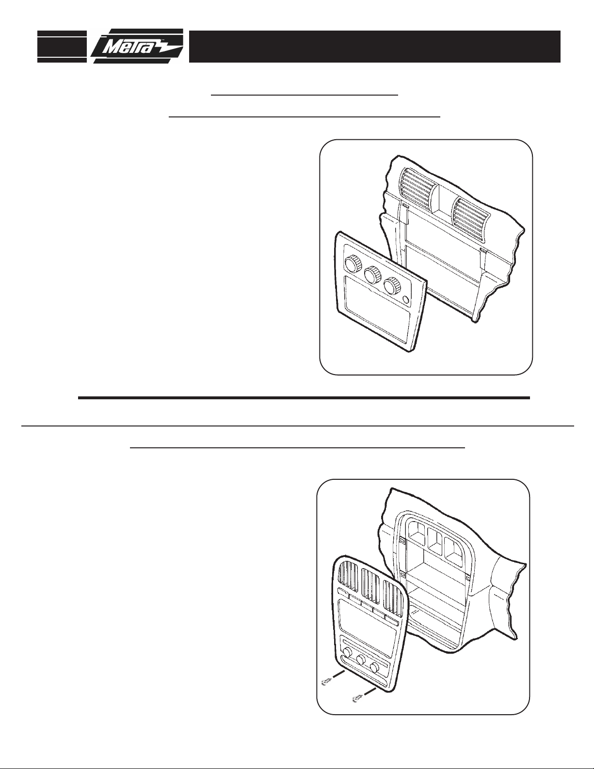
DODGE NEON 2000-2006
PLYMOUTH NEON 2000-2001
Disconnect the negative battery
1
terminal to prevent an accidental
short circuit.
2
Pull off climate control knobs.
Unclip and remove ac/heater vents.
3
4
Remove (1) Phillips head screw from
each vent cavity.
5
Unclip and remove dash trim panel.
6
Remove (4) Phillips head screws
securing the radio. Disconnect and
remove the radio. Skip to kit assembly page.
DASH DISASSEMBLY
DODGE RAM 2002-2005
Disconnect the negative battery
1
terminal to prevent an accidental
short circuit.
2
Unclip the top edge of the trim panel
below the steering column. (It is not
necessary to completely remove this
panel).
Remove (1) Phillips head screw from
3
below right ac/heater vent.
4
Unclip and remove dash trim panel.
5
Remove (4) Phillips head screws
securing the radio. Disconnect and
remove the radio. Skip to kit assembly page.
3
Page 6

99-6505
3 Screws
3 Screws
2 Screws
JEEP GRAND CHEROKEE 1999-2004
Disconnect the negative battery
1
terminal to prevent an accidental
short circuit.
2
Unclip and remove radio trim panel.
Remove (4) Phillips head screws
3
securing the radio. Disconnect and
remove the radio. Skip to kit assembly page.
DASH DISASSEMBLY
1
2
3
4
DODGE DAKOTA 2001-2004
DURANGO 2001-2003
Disconnect the negative battery
terminal to prevent an accidental
short circuit.
Remove (3) T-20 Torx screws from
the bottom edge of the panel below
the steering column and unsnap to
remove panel.
Remove (2) Phillips screws from the
instrument cluster panel above
gauges.
Remove (3) T-20 Torx screws from
the bottom of the steering column
shroud and unsnap and remove the
top half of the shroud.
5
Unsnap and remove entire panel surrounding radio, a/c controls, and
instrument cluster.
6
Remove (4) Phillips screws securing
radio. Disconnect and remove radio.
Skip to kit assembly page.
4
Page 7
1
2
3
4
POWER
OUTLET
99-6505
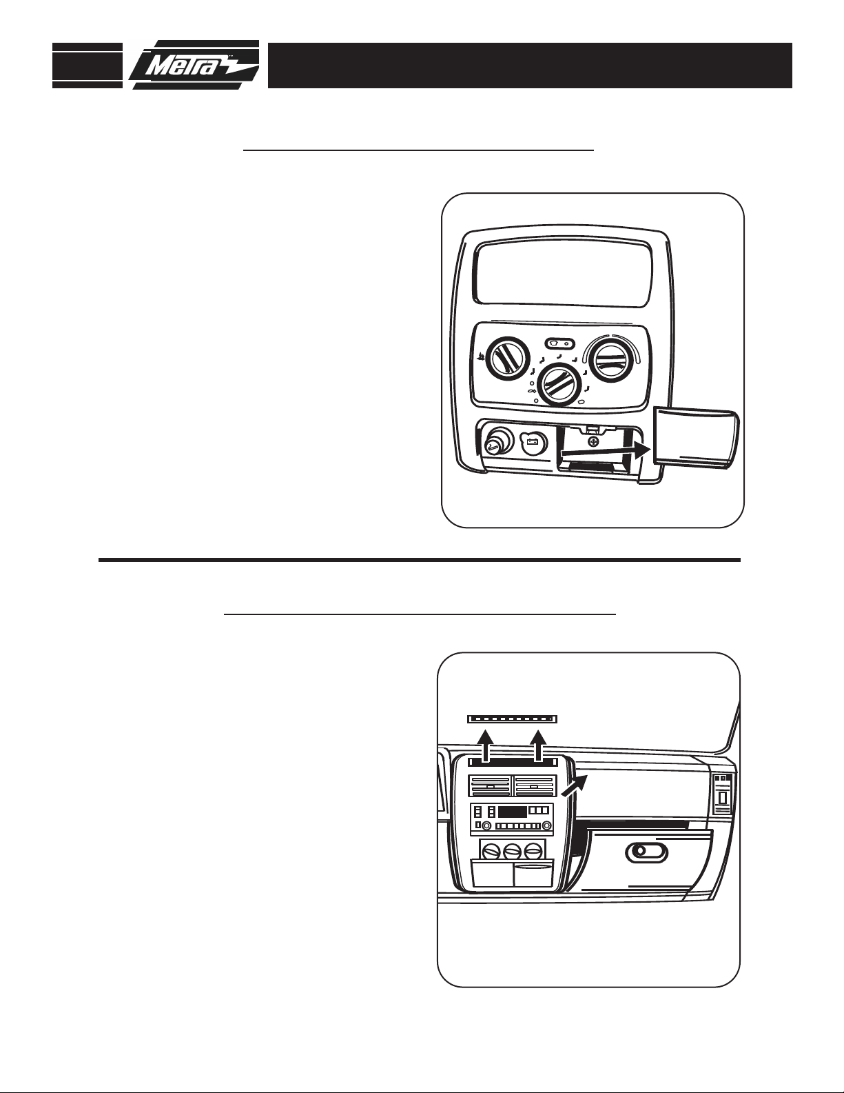
JEEP LIBERTY 2002-2007
Disconnect the negative battery
1
terminal to prevent an accidental
short circuit.
2
Remove ashtray and remove one
Phillips screw exposed.
Unclip and remove radio/ climate
3
control panel.
4
Remove (4) Phillips screws securing
radio. Disconnect and remove radio.
Skip to kit assembly page.
DASH DISASSEMBLY
JEEP WRANGLER 2003-2006
Disconnect the negative battery
1
terminal to prevent an accidental
short circuit.
2
Unsnap and remove defroster grille
panel near windshield.
Remove two Phillips screws exposed
3
at the top of the center dash panel
and unsnap and remove panel.
4
Remove glove box door to access
one 10mm nut on back of radio.
5
Remove (4) Phillips screws securing
radio. Disconnect and remove radio.
Skip to kit assembly page.
5
Page 8

99-6505
DODGE VIPER 2003-2009
Disconnect the negative battery
1
terminal to prevent an accidental
short circuit.
2
Using a small flat blade screw driver,
pry up on center console trim panel.
(Be careful not to scratch the trim
panel)
Loosen the shifter lock nut below
3
center console trim panel
and unscrew the shifter knob.
(Figure B)
4
Unplug electrical connectors and
remove center console trim panel.
(Figure C)
(Figure A)
(Figure A)
DASH DISASSEMBLY
A
B
5
Remove (6) Allen screws from
radio/climate control trim panel and
(1) Phillips screw at the bottom of
the panel.
6
Unplug electrical connectors and
remove the panel.
Remove (4) screws securing the
7
radio. Disconnect and remove the
radio.
D
(Figure D)
C
6
Page 9

99-6505
DIN HEAD UNIT PROVISION
Slide the DIN cage into the Radio
1
Housing and secure by bending the
metal locking tabs down.
Slide the aftermarket head unit into
2
the cage and secure.
(Figure B)
KIT ASSEMBLY
A
(Figure A)
B
7
Page 10

99-6505
KIT ASSEMBLY
ISO DIN HEAD UNIT PROVISION
Align the holes in the ISO Snap In
1
Brackets with the holes in the head
unit and mount the brackets to the
head unit with the screws supplied
with the unit.
Slide the head unit/bracket assembly
2
into the radio opening until the side
clips engage.
Snap the ISO Trimplate over the head
3
unit.
(Figure B)
(Figure A)
(Figure B)
A
B
8
Page 11

99-6505
FINAL ASSEMBLY
FINAL ASSEMBLY
Locate the factory wiring harness in the dash and make the connection as shown.
1
Metra recomends using the proper mating adapter and making the connections as
shown. (Isolate and individually tape off the ends of any unused wires to prevent
electrical short circuit.)
Re-connect the negative battery terminal and test the unit for proper operation.
2
3
Reassemble radio and dash assemblies in reverse order of disassembly.
FINAL WIRING CONNECTIONS
Make wiring connections using the EIA color code chart shown below and the instructions included with the head
unit. Metra recommends making connections as shown below; Strip, Splice, Solder, Tape. Isolate and individually
tape off ends of any unused wires to prevent electrical short circuit.
A
B
C
D
A) Strip wire ends back 1/2"
B)
C) Solder
D) Tape
METRA / EIA WIRING CODE
12V Ignition / Acc . . . Red
12V Batt / Memory . . Yellow
Ground . . . . . . . . . . . Black*
Power Antenna . . . . . Blue
Amp Turn-On . . . . . . Blue / White
Right Front (+) . . . . . Gray
Right Front (-) . . . . . . Gray / Black
Left Front (+) . . . . . . White
Left Front (-) . . . . . . . White / Black
Right Rear (+). . . . . . Violet
Twist ends together
Amp Ground . . . . . . . Black / White
Illumination. . . . . . . . Orange
Dimmer . . . . . . . . . . Orange / White
*NOTE: When Black a wire is not present, ground radio to vehicle chassis.
All colors may not be present on all leads due to manufacturer’s specifications.
Right Rear (-) . . . . . . Violet / Black
Left Rear (+). . . . . . . Green
Left Rear (-) . . . . . . . Green / Black
9
Page 12

99-6505 INSTRUCTIONS
1-800-221-0932 www.metraonline.com
REV. 05/04/10
© COPYRIGHT 2010 METRA ELECTRONICS CORPORATION INST99-6505
 Loading...