

Page 1
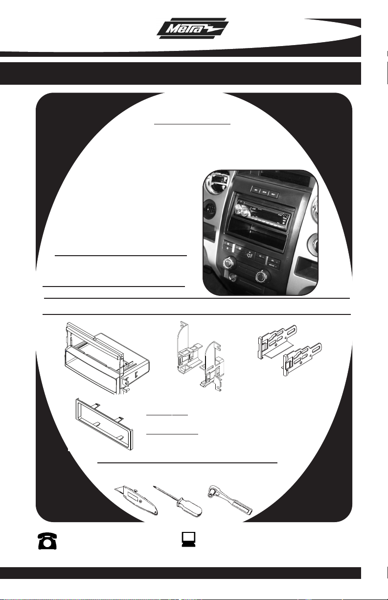
INSTALLATION INSTRUCTIONS FOR PART 99-5819
APPLICATIONS
FORD
F-150 (XL Models Only) 2009-10
99-5819
KIT FEATURES
• DIN Radio Provision With Pocket
• ISO Mount Radio Provision With Pocket
KIT COMPONENTS
• A) Radio Housing • B) Radio Housing Brackets • C) ISO Brackets • D) Trim Plate
A
D
Cutting Tool • Phillips Screwdriver • Socket Wrench
B
WIRING AND ANTENNA CONNECTIONS (Sold Separately)
Wire harness:
• 70-5520 Ford harness 2003-up
Antenna adapter:
• 40-CR10 Chrysler antenna 2002-up
TOOLS REQUIRED:
1-800-221-0932
© COPYRIGHT 2010 METRA ELECTRONICS CORPORATION
C
www.metraonline.com
Page 2
99-5819
TABLE OF CONTENTS
Dash Disassembly
-
FORD F-150 (XL Models Only) 2009-10 . . . . . . . . . . . . . . .
. . .1
Kit Assembly
- DIN Radio Provision With Pocket . . . . . . . . . . . . . . . . . . . . . . . . . . . . . 2
- ISO Mount Radio Provision With Pocket. . . . . . . . . . . . . . . . . . . . . . . . 3
Final
Assembly . . . . . . . . . . . . . . . . . . . . . . . . . . . . . . . . . . . . . . . . . . .4
*Note:
Refer also to the instructions included with the aftermarket radio.
Page 3
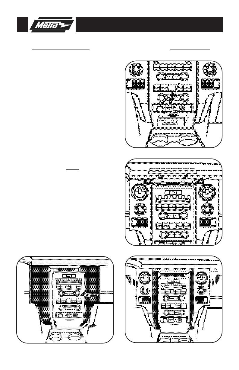
99-5819 DASH DISASSEMBLY
FORD F-150 (XL Models Only)2009-10
Disconnect the negative battery
1
terminal to prevent an accidental
short circuit.
2
Unclip and remove the switch panel
to the right of the cigarette lighter
then remove the (1) 9/32” screw
exposed. (
Remove the rubber pad at the top of
3
the radio trim panel then remove the
(2) 9/32” screws exposed. (
4
Unclip and pull the side panels containing the a/c vents away from the
radio trim panel. Note:
essary to remove the panels completely. (
5
Unclip and remove the radio trim
panel. (
Figure A)
Figure B)
It is not nec-
Figure C)
Figure D)
A
B
Remove (4) 9/32” screws to remove
6
the factory radio.
Continue to kit assembly.
D
C
1
Page 4

99-5819 KIT ASSEMBLY
CUT HERE -TOP LEG ONLY
CUT HERE -TOP LEG ONLY
CUT
C
UT
DIN RADIO PROVISION WITH POCKET
*Note: Refer also to the instructions included with the aftermarket radio.
A
1
Cut and remove the top (2) mounting
holes off of the radio housing.
The notch in the housing
Note:
should be on top.
2
Slide the included brackets onto the
sides of the radio housings pocket
from the back of the housing
forward.
3
Slide the DIN cage into the Radio
(Figure B)
Housing and secure by bending the
metal locking tabs down.
Slide the aftermarket head unit into
4
the cage and secure.
Continue to final assembly.
(Figure A)
(Figure C)
(Figure D)
B
D
C
2
Page 5

99-5819 KIT ASSEMBLY
CUT HERE -TOP LEG ONLY
CUT HERE -TOP LEG ONLY
CUT
CUT
ISO MOUNT RADIO PROVISION WITH POCKET
*Note: Refer also to the instructions included with the aftermarket radio.
1
Cut and remove the top (2) mounting
holes off of the radio housing.
The notch in the housing
Note:
should be on top.
2
Slide the included brackets onto the
(Figure A)
sides of the radio housings pocket
from the back of the housing
forward.
3
Mount the ISO Brackets to the head
(Figure B)
unit with the screws supplied with
the unit.
4
Slide the head unit into the radio
(Figure C)
opening until the side clips engage.
(Figure D)
A
B
Snap the trim plate into the Radio
5
Housing.
(Figure D)
Continue to final assembly.
D
C
3
Page 6

99-5819 FINAL ASSEMBLY
FINAL ASSEMBLY
FINAL ASSEMBLY
A
B
(A) Strip wire ends back 1/2"
B) Twist ends together
C
C) Solder
D) Tape
D
Locate the factory wiring harness in the dash. Metra recommends using the proper mating
1
adapter and making the connections as shown. (Isolate and individually tape off the ends of
any unused wires to prevent electrical short circuit).
Re-connect the negative battery terminal and test the unit for proper operation.
2
Position the factory bracket/aftermarket radio assembly into the dash and secure using
3
the factory hardware.
Secure the Double DIN radio housing to the sub dash using the factory hardware.
4
Reassemble the rest of the dash in reverse order of disassembly.
5
FINAL WIRING CONNECTIONS
Make wiring connections using the EIA color code chart shown below and the instructions
included with the head unit. Metra recommends making connections shown below; Strip, Splice,
Solder, Tape. Isolate and individually tape off ends of any unused wires to prevent electrical short
circuit.
METRA / EIA WIRING CODE
12V Ignition / Acc . . . . . . . . . . Red
12V Batt / Memory. . . . . . . . . Yellow
Ground. . . . . . . . . . . . . . . . . . Black*
Power Antenna. . . . . . . . . . . . Blue
Amp Turn-On . . . . . . . . . . . . . Blue / White
Amp Ground. . . . . . . . . . . . . . Black / White
Illumination . . . . . . . . . . . . . . Orange
Dimmer . . . . . . . . . . . . . . . . . Orange / White
*NOTE:
When a Black wire is not present, ground radio to vehicle chassis. All colors may not be
present on all leads due to manufacturer’s specifications.
Right Front (+) . . . . . . . . . . . . Gray
Right Front (-). . . . . . . . . . . . . Gray/ Black
Left Front (+) . . . . . . . . . . . . . White
Left Front (-). . . . . . . . . . . . . . White / Black
Right Rear (+) . . . . . . . . . . . . Violet
Right Rear (-) . . . . . . . . . . . . . Violet / Black
Left Rear (+) . . . . . . . . . . . . . Green
Left Rear (-) . . . . . . . . . . . . . . Green / Black
4
Page 7

99-5819
NOTES
5
Page 8

99-5819 INSTRUCTIONS
1-800-221-0932
REV. 04/23/10 © COPYRIGHT 2010 METRA ELECTRONICS CORPORATION INST99-5819
www.metraonline.com
 Loading...