

Page 1
INSTALLATION INSTRUCTIONS FOR PART 99-5816
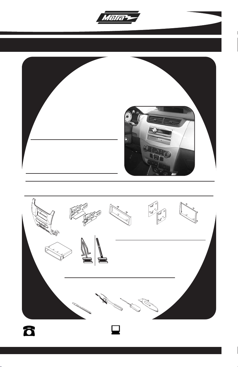
APPLICATIONS
FORD Focus
2008-2011
99-5816
KIT FEATURES
• DIN Radio Provision with Pocket
• ISO Mount Radio Provision with Pocket
• Double DIN Radio Provision
• Stacked ISO Mount Units Provision
• Painted To Match Factory Dash
KIT COMPONENTS
• A) Radio Housing • B) ISO Brackets • C) ISO Trim Plate • D) Double DIN Brackets
• E) Double DIN Trim Plate • F) Pocket • G) (2) Top Clips and (4) Middle Radio Housing Clips
B
A
SIDE VIEW
SIDE VIEW
G
F
Small Flat Blade Screwdriver/ Panel Removal Tool
• Phillips Screwdriver • Socket Set • Cutting Tool
(4) MIDDLE CLIPS
(2) TOP CLIPS
TOOLS REQUIRED:
1-800-221-0932
© COPYRIGHT 2004-2008 METRA ELECTRONICS CORPORATION
C
Wiring & Antenna Connections (sold seperately)
XSVI-5520-NAV - Ford Interface
AFSI-02 - if equipped w/ sync
70-5522 - Ford Sub Harness
D
E
www.metraonline.com
Page 2

99-5816
TABLE OF CONTENTS
Dash Disassembly
-
Ford Focus 2008-2011 . . . . . . . . . . . . . . . . . . . . . . . . . . . . .
.. 1,2
Kit Assembly
- Kit Preparation . . . . . . . . . . . . . . . . . . . . . . . . . . . . . . . . . . . . . . . . . . 3
- DIN Mount Radio Provision with Pocket . . . . . . . . . . . . . . . . . . . . . . . .4
- ISO Mount Radio Provision with Pocket . . . . . . . . . . . . . . . . . . . . . . . .5
- Double DIN /Stacked ISO Mount Units Radio Provision . . . . . . . . . . . . .6
Final Assembly
Note:
Refer also to the instructions included with the aftermarket radio.
. . . . . . . . . . . . . . . . . . . . . . . . . . . . . . . . . . . . . . . . . . .7
KNOWLEDGE IS POWER
Enhance your installation and fabrication skills by
enrolling in the most recognized and respected
mobile electronics school in our industry.
Log onto www.installerinstitute.com or call
800-354-6782 for more information and take steps
toward a better tomorrow.
Page 3
95-5816 DASH DISASSEMBLY
PAS
S
AIRBAG
OFF
PAS
S
AIRBAG
OFF
PAS
S
AIRBAG
OFF
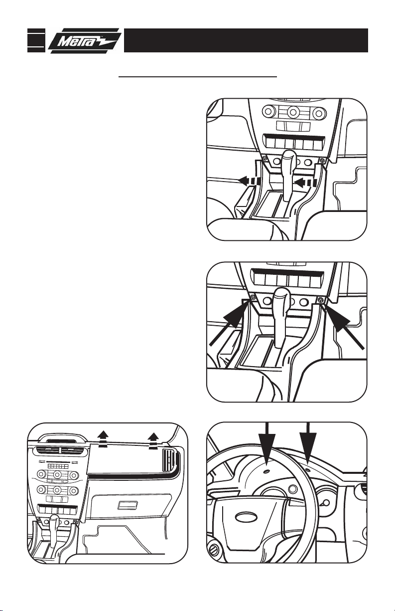
FORD FOCUS 2008-2011
1
Disconnect the negative battery termi-
nal to prevent an accidental short circuit.
2
Unclip and remove the trim panel surrounding the shifter and including the
cup holders.
3
Remove (2) 9/32” screws from the bottom edge of the factory radio trim
panel.
4
Remove (2) 9/32” screws facing up
above the gauge cluster then unclip
and remove the trim panel surrounding
the gauge cluster.
5
Unclip and remove the trim panel
above the glove box.
(Figure A)
(Figure B)
(Figure C)
(Figure D)
A
B
Continue on page 2.
D
C
1
Page 4
95-5816 DASH DISASSEMBLY
1
2
3
4
5
7
8
9
0
6
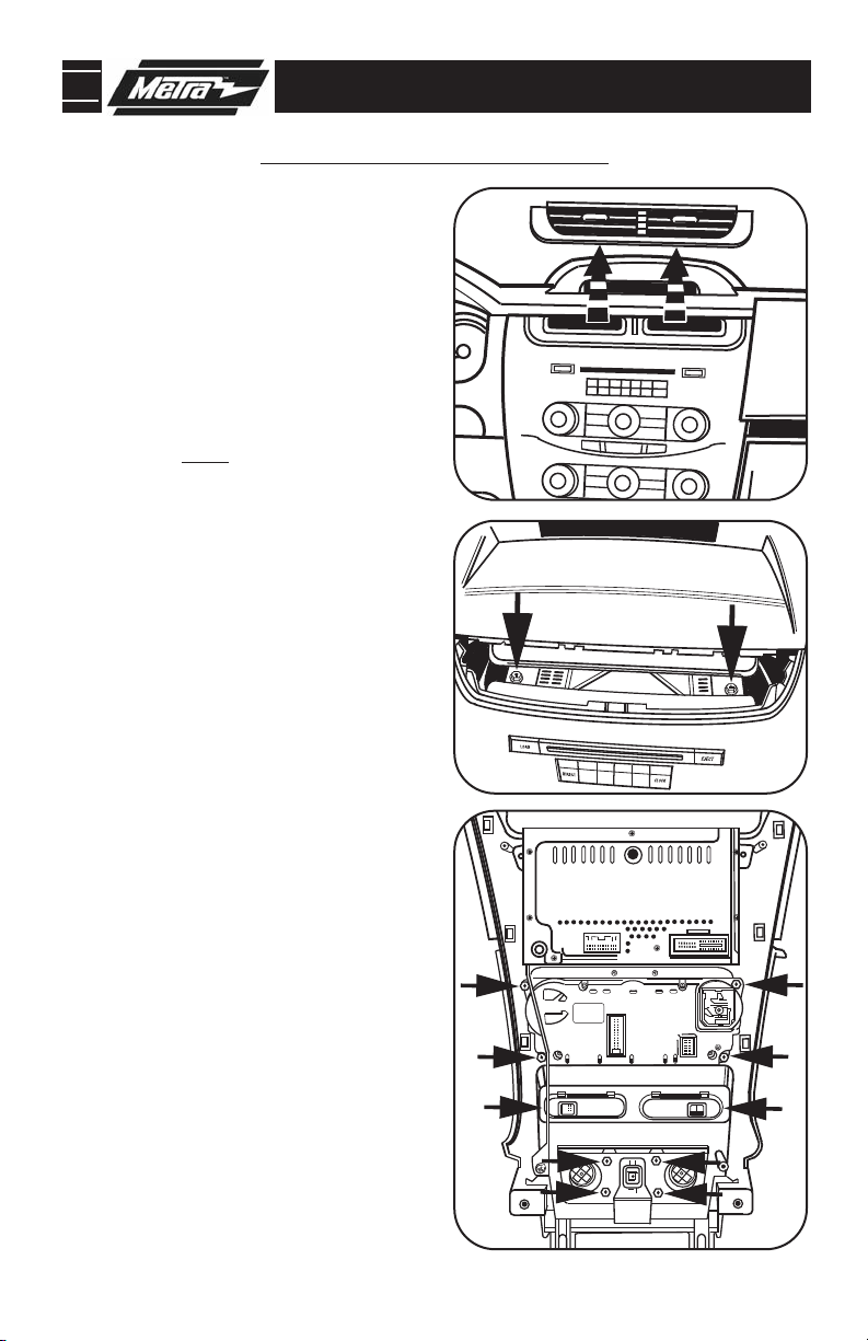
FORD FOCUS 2008-2011
6
Unclip and remove the vent panel at
the top of the factory radio trim panel.
(Figure E)
7
Remove (2) 9/32” screws behind the
vent panel removed in step 6.
(Figure F)
8
Unclip the factory radio trim panel
assembly. Unplug and re
assembly. Note: Some early models
had a ground strap attached to the
radio chassis and the sub dash with
an 8 MM bolt. You will need to unbolt
this strap to remove the factory radio
trim panel assembly.
9
Remove (4) T-20 Torx screws securing
the climate controls to the factory
radio trim panel assembly and
remove the controls from the assembly. (Retain the screws and climate
controls for re-use during kit prepara-
(Figure G)
tion.)
move the
E
F
10
Remove (4) T-20 Torx screws securing
the accessory socket panel to the
factory radio trim panel assembly and
remove the socket panel from the
assembly. (Retain the screws and
accessory socket panel for re-use
during kit preparation.)
11
Unclip and remove the passenger air
(Figure G)
bag light and the switch panel blank
plates. (Retain the air bag light and
blank plates for re-use during kit
preparation.)
(Figure G)
Continue to kit preparation.
G
2
Page 5

99-5816 KIT ASSEMBLY
KIT PREPARATION
Secure the climate control into the
1
radio housing using the factory hard-
ware. (
Figure A)
Secure the accessory socket panel to
2
the radio housing using the factory
hardware. (
Clip the passenger air bag light and
3
Figure B)
the switch panel blank plates in to
the radio housing. (
4
Attach Top and Middle Radio Housing
Figure C)
Clips to the back of the radio housing.
Figure D,E)
(
NOTE: When the clips are properly
attached they should be on a 90
degree angle with the radio housing.
SIDE VIEW
FRONT VIEW
SIDE VIEW
FRONT VIEW
D
A
B
(2) TOP CLIPS
(4) MIDDLE CLIPS
C
E
3
Page 6

99-5816 KIT ASSEMBLY
DIN MOUNT RADIO PROVISION WITH POCKET
*Note: Refer also to the instructions included with the aftermarket radio.
A
1
Slide the DIN cage into the radio housing and secure by bending the metal
locking tabs outward.
2
Slide the aftermarket radio into the DIN
cage and until it snaps into place.
3
Snap the pocket into the radio housing.
(Figure C)
Continue to final assembly.
(Figure A)
B
4
C
Page 7

99-5816 KIT ASSEMBLY
ISO MOUNT RADIO PROVISION WITH POCKET
*Note: Refer also to the instructions included with the aftermarket radio.
1
Mount the ISO Brackets to the radio
using the screws supplied with the
(Figure A)
radio.
2
Slide the radio into the radio housing
until it snaps into place.
3
Snap the trim plate onto the front of
the Radio Housing.
4
Snap the Pocket into the radio
housing.
(Figure C)
(Figure B)
(Figure B)
A
Continue to final assembly.
B
C
5
Page 8

99-5816 KIT ASSEMBLY
DOUBLE DIN/STACKED ISO MOUNT
UNITS RADIO PROVISION
*Note: Refer also to the instructions included with the aftermarket radio.
1
Cut and remove the center bar from
the radio housing.
2
Snap the Double DIN brackets to the
inside edge of the radio housing.
(Figure B)
3
Slide the Double DIN or stacked ISO
mount unit(s) into the bracket/radio
housing assembly and secure the
unit(s) to the assembly using the
screws supplied with the unit(s).
(Figure C)
4
Snap the double DIN trim plate onto
the front of the radio housing.
(Figure C)
(Figure A)
A
B
Continue to final assembly.
C
6
Page 9

99-5816 FINAL ASSEMBLY
FINAL ASSEMBLY
A
(A) Strip wire ends back 1/2"
B
B) Twist ends together
C) Solder
C
D
Locate the factory wiring harness in the dash. Metra recommends using the
1
proper mating adapter and making connections as shown. (Isolate and individually tape off the ends of any unused wires to prevent electrical short circuit.)
2
Re-connect the negative battery terminal and test the unit for proper operation.
Reassemble radio and dash assemblies in reverse order of disassembly.
3
D) Tape
FINAL WIRING CONNECTIONS
Make wiring connections using the EIA color code chart shown below and the instructions included with the
head unit. Metra recommends making connections as shown below; Strip, Splice, Solder, Tape. Isolate and
individually tape off ends of any unused wires to prevent electrical short circuit.
METRA / EIA WIRING CODE
12V Ignition / Acc . . . . . . . . . . Red
12V Batt / Memory. . . . . . . . . Yellow
Ground. . . . . . . . . . . . . . . . . . Black*
Power Antenna. . . . . . . . . . . . Blue
Amp Turn-On . . . . . . . . . . . . . Blue / White
Amp Ground. . . . . . . . . . . . . . Black / White
Illumination . . . . . . . . . . . . . . Orange
Dimmer . . . . . . . . . . . . . . . . . Orange / White
Right Front (+) . . . . . . . . . . . . Gray
Right Front (-). . . . . . . . . . . . . Gray/ Black
Left Front (+) . . . . . . . . . . . . . White
Left Front (-). . . . . . . . . . . . . . White / Black
Right Rear (+) . . . . . . . . . . . . Violet
Right Rear (-) . . . . . . . . . . . . . Violet / Black
Left Rear (+) . . . . . . . . . . . . . Green
Left Rear (-) . . . . . . . . . . . . . . Green / Black
*NOTE: When a Black wire is not present, ground radio to vehicle chassis.
All colors may not be present on all leads due to manufacturer’s specifications.
7
Page 10

99-5816
NOTES
8
Page 11

99-5816
NOTES
9
Page 12

99-5816 INSTRUCTIONS
1-800-221-0932
REV. 11/18/10 © COPYRIGHT 2004-2010 METRA ELECTRONICS CORPORATION INST99-5816
www.metraonline.com
 Loading...