

Page 1
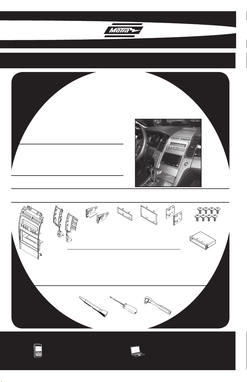
INSTALLATION INSTRUCTIONS FOR PART 99-5721
APPLICATIONS
2010 FORD TAURUS
(NON-NAV)
99-5721
KIT FEATURES
• DIN Head unit provisions with pocket
• ISO DIN Head unit provision with pocket
• DDIN Head unit provisions
• ISO Stacked head unit provisions
• Painted Silver to match factory nish
KIT COMPONENTS
• A) Radio Housing/Climate Control • B) (2) A/C Vent Trim Panels • C) ISO Brackets • D) ISO Trim Plate
• E) DDIN Brackets • F) DDIN Trim Plate • G) (10) #8x3/8” Phillips Screws • H) Pocket
A
B
C D
E F
G
H
WIRING & ANTENNA CONNECTIONS (Sold Separately)
• FRST - CAN BUS/RSE/THX/SYNC Interface
• XSVI-5520-NAV - Ford CAN BUS Interface
• AFDI-THX-01 - Ford Premium Sound Interface
• 40-EU10 - Antenna Adapter
TOOLS REQUIRED
• Panel Removal Tool • Phillips Screwdriver • Socket Wrench
METRA. THE WORLD’S BEST KITS.™
1-800-221-0932 metraonline.com
© COPYRIGHT 2004-2010 METRA ELECTRONICS CORPORATION
Page 2

TABLE OF CONTENTS
DASH DISASSEMBLY
• 2010 FORD TAURUS . . . . . . . . . . . . . . . . . . . . . . 1-3
KIT PREPARATION
• 2010 FORD TAURUS . . . . . . . . . . . . . . . . . . . . . . . . 4
KIT ASSEMBLY
2010 FORD TAURUS
• DIN HEAD UNIT PROVISION . . . . . . . . . . . . . . . . . . . 5
• ISO DIN HEAD UNIT PROVISION . . . . . . . . . . . . . . . 6
• DDIN / STACKED ISO DIN HEAD UNIT PROVISION . . 7
CUSTOMIZING THE DISPLAY
• 2010 FORD TAURUS . . . . . . . . . . . . . . . . . . . . . . 8-9
*NOTE: Refer also to the instructions included with the aftermarket radio.
KNOWLEDGE IS POWER
Enhance your installation and fabrication skills by
enrolling in the most recognized and respected
mobile electronics school in our industry.
Log onto www.installerinstitute.com or call
800-354-6782 for more information and take steps
toward a better tomorrow.
Metra recommends MECP certified technicians
Page 3
99-5721 DASH DISASSEMBLY
2010 FORD TAURUS
Disconnect the negative battery
1
terminal to prevent an accidental
short circuit.
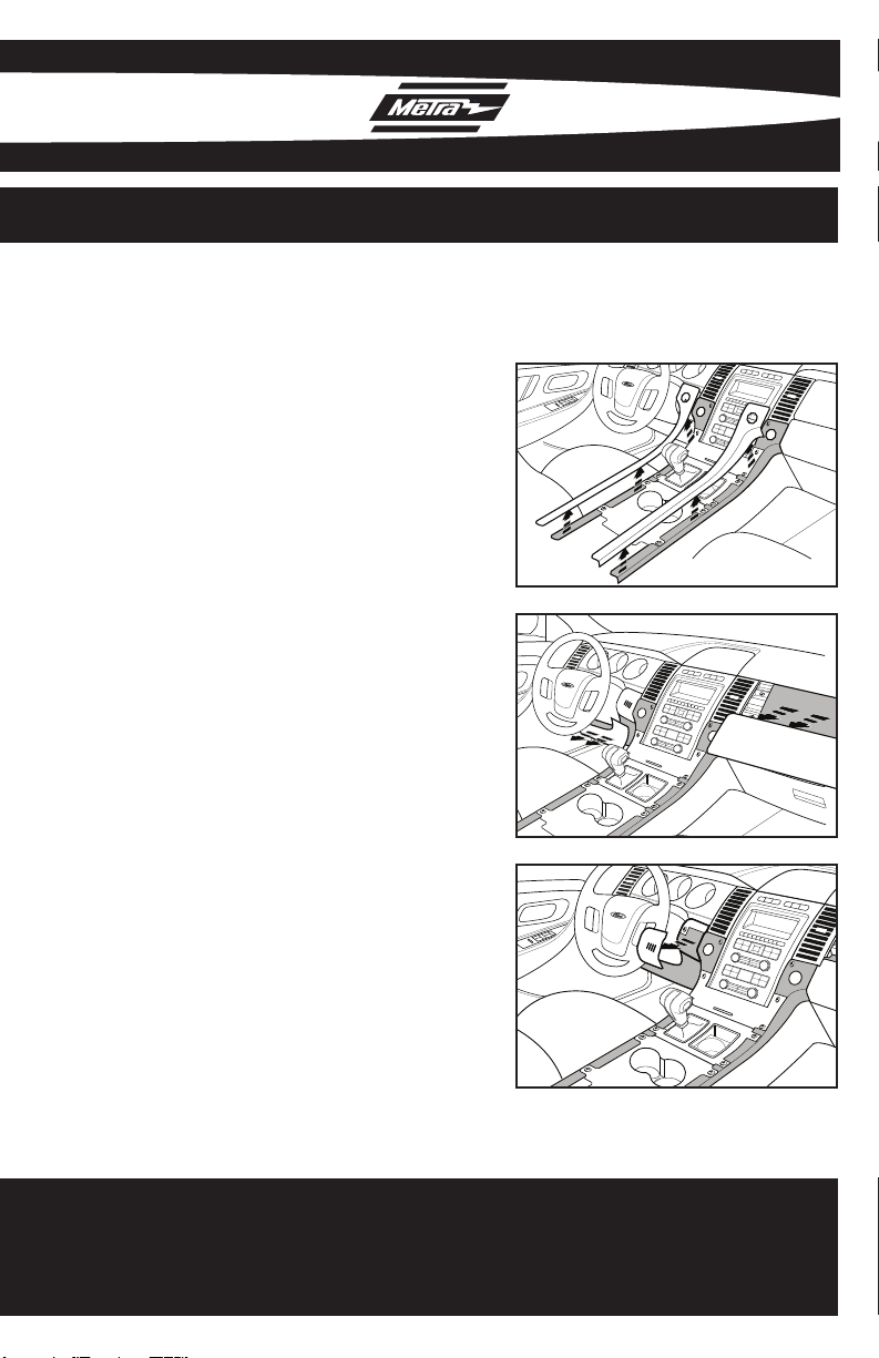
2
Unclip and remove the (2) trim
panels on the left and right side of
the cup holders and shifter. (Fig. A)
A
Unclip and remove the trim panel to
3
the right of the passenger a/c vent.
(Fig. B)
Unclip and remove the knee bolster
4
panel below the steering column.
(Fig. B)
Remove (1) 9/32” screw from the
5
trim panel to the left of the steering
column that has the interior light
dimmer switch in it.
6
Unclip and remove the trim panel
between the steering column and
the key cylinder. (Fig. C)
B
C
Continued on Pg. 2 .......................
1
Page 4
99-5721 DASH DISASSEMBLY
2010 FORD TAURUS
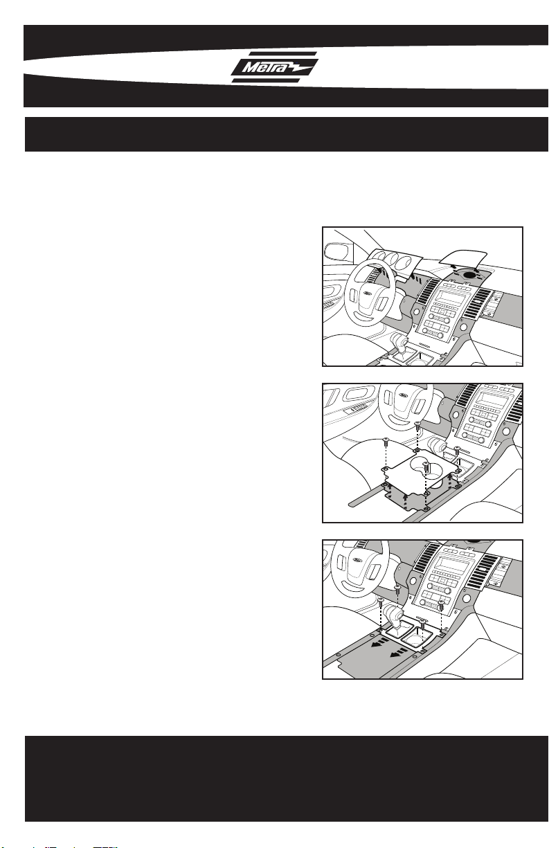
Unclip and remove the gauge cluster
7
trim panel. (Fig. D)
Unclip and remove the trim panel/
8
speaker grill from above the radio
trim panel. (Fig. D)
Remove (4) Phillips screws from the
9
cup holder trim panel then unclip
and remove the panel.
(Fig. E)
Remove (4) Phillips screws from
10
the shifter trim panel then slide it
backwards. Note: There is no need
to remove this panel completely.
(Fig. F)
D
E
F
2
Continued on Pg. 3 .......................
Page 5
99-5721 DASH DISASSEMBLY
2010 FORD TAURUS
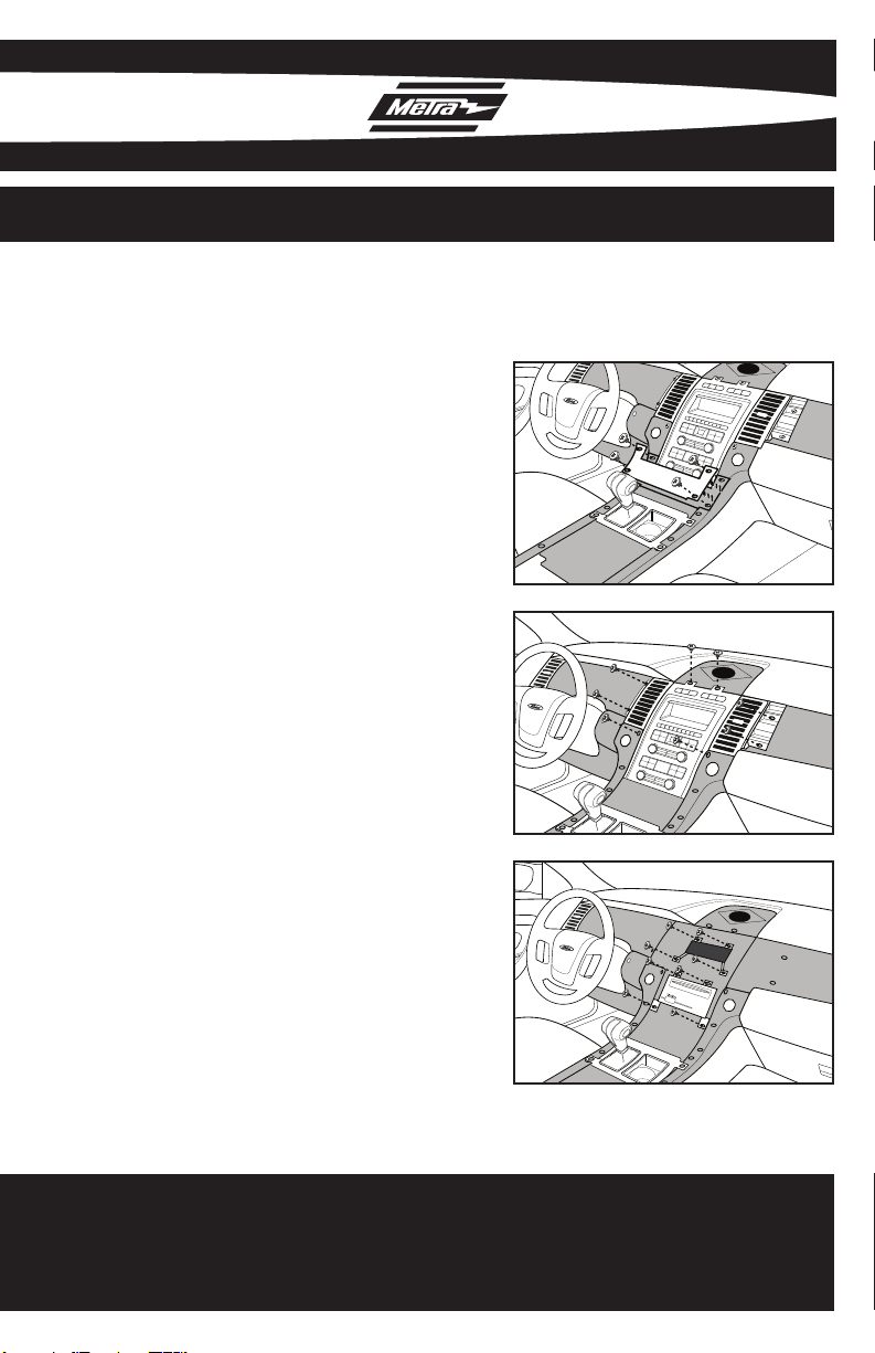
Remove (4) Phillips screws from the
11
ash tray trim panel then unclip and
remove the ash tray assembly.
(Fig. G)
Remove (10) phillips screws from
12
the radio trim panel including the a/c
vents then unclip and remove the
panel. (Fig. H)
Remove (4) Phillips screws securing
13
the radio display. (Fig. I)
Remove (4) Phillips screws securing
14
the radio. (Fig. I)
G
H
Unclip and remove the a/c vents
15
and chrome vent trim from the
factory panel.
I
Continue to kit preparation............
3
Page 6

99-5721 KIT PREPARATION
2010 FORD TAURUS
Attach the left and right a/c vent trim
1
panels to the main radio housing
panel using the provided (10)
#8X3/8” Phillips screws. (Fig. A)
Snap the a/c vents and chrome vent
2
trim into the appropriate vent trim
panel. Note: The vents are labeled L
and R on the tops.
A
4
Continue to kit assembly...............
Page 7

99-5721 KIT ASSEMBLY
DIN HEAD UNIT PROVISION
Slide the DIN cage into the Radio
1
Housing and secure by bending the
metal locking tabs down. (Fig. A)
2
Snap the pocket into the bottom
opening of the radio housing. (Fig. B)
Slide the aftermarket head unit into
3
the cage and secure. (Fig. C)
Locate the factory wiring harness
4
and antenna plug in the dash. Metra
recommends using the proper
mating adapters from Metra and/or
AXXESS.
A
B
Plug the jumper harness into the car
5
side of the climate control plug and
the other side into the kit.
Reassemble dash in reverse order
6
of disassembly.
C
5
Page 8

99-5721 KIT ASSEMBLY
ISO DIN HEAD UNIT PROVISION
Mount the ISO Brackets to the head
1
unit with the screws supplied with
the unit. (Fig. A)
Snap the pocket into the bottom
2
opening of the radio housing. (Fig. B)
3
Slide the head unit into the radio
opening until the side clips engage.
(Fig. C)
Snap the Trim plate into the Radio
4
Housing. (Fig. C)
Locate the factory wiring harness
5
and antenna plug in the dash. Metra
recommends using the proper
mating adapters from Metra and/or
AXXESS.
Plug the jumper harness into the car
6
side of the climate control plug and
the other side into the kit.
A
B
C
Reassemble dash in reverse order
7
of disassembly.
6
Page 9

99-5721 KIT ASSEMBLY
DDIN / STACKED ISO DIN
HEAD UNIT PROVISION
1
Cut and remove the center bar from
the radio housing. (Fig. A)
Snap the Double DIN brackets to the
2
inside edge of the Double DIN trim
plate. (Fig. B)
Slide the Double DIN head unit or
3
stacked ISO head units into the
bracket/radio housing assembly and
secure the Double DIN head unit
or stacked ISO head units to the
assembly using the screws supplied
with the radio. (Fig. C)
4
Snap the double DIN trim plate into
the radio housing. (Fig. C)
Locate the factory wiring harness in
5
the dash. Metra recommends using
the proper mating adapter from
Metra or AXXESS. Re-connect the
negative battery terminal and test
the unit for proper operation.
A
B
C
Plug the jumper harness into the car
6
side of the climate control plug and
the other side into the kit.
Reassemble dash in reverse order
7
of disassembly.
7
Page 10

99-5721 KIT ASSEMBLY
CUSTOMIZING THE DISPLAY
Changing The Display Back Light Color
1. Press the Passenger Heated Seat button for 10 seconds, the unit will go into
“Congure Backlight Color” mode. The display will show “Red Green Blue”
with number assigned to each color contributing to the overall back light color
while in this mode. Each number will be between 0-255.
2. Press and hold the Fan + button to increase Red.
3. Press and hold the Fan - button to decrease Red.
4. Press and hold the Front Defrost button to increase Green.
5. Press and hold the Power button to decrease Green.
6. Press and hold the Rear Defrost button to increase Blue.
7. Press and hold the Driver Heated Seat button to decrease Blue.
8. After you choose your color stop pressing the buttons and after 10 seconds
the color chosen will stay.
Changing The Display Contrast
1. Press the Driver Heated Seat button for 10 seconds, the unit will go into
“Congure Display Contrast” mode.
2. Press the Temp +/- buttons to adjust the display contrast up and down.
3. After 10 seconds of no buttons being pressed the chosen contrast will stay.
Main Screen Text Customization
1. Press and hold the MAX A/C button for 10 seconds. The current home
8
Page 11

99-5721 KIT ASSEMBLY
screen will then be displayed and the cursor will appear and blink. It will be
located in the 1st location on the top row.
2. To modify the text :
A. Use the FAN buttons to move the cursor forward or back. The
location where the cursor is blinking is the location that the character
may be changed.
• FAN DOWN = Move Cursor ahead one location
• FAN UP = Move Cursor back one location
B. To change the character where the cursor is currently blinking use the
TEMP buttons to progress through the character set.
• TEMP UP = Show the next character
• TEMP DOWN = Show the previous character
3. To exit this mode:
A. Do not press ANY buttons for 15 seconds and it will timeout
automatically.
B. Press button other than the 4 mentioned above.
4. To erase any changes made to the default display – Press and hold down the
recirculation button button for 15 seconds. The “TAURUS” will once again be
the default display.
NOTE : Characters are saved into memory immediately whenever changes are
made.
NOTE : While in this mode – no other display items will be updated.
9
Page 12

99-5721 KIT ASSEMBLY
Dual Zone Temperature Controls
(allows 99-5721 to operate in a dual-zone climate controlled car)
1. Press the Temp Down and Passenger Heated Seat button simultaneously to
enter Dual Zone Set Mode. Note: The ZONE icon will light to indicate that
you are in dual zone mode, and the temperature bar graph will ash.
2. Press the Temp Up and Temp Down buttons to set the passenger
temperature set point.
3. Press no buttons for 5 seconds and the temperature bar graph will stop
ashing and the Temp Up and Temp Down buttons will adjust the drivers
temperature set point. Note: The Zone icon will stay on indicating that dual
zone mode is still active.
4. Press the Temp Down and the Passenger Heated Seat button simultaneously
while the Temperature Bar Graph is ashing to exit dual zone mode. Note:
The driver temperature set point will now be used for both sides.
5. Note: When adjusting either set point the ambient temperature display will
show the actual set point then revert back to ambient after 2-3 seconds.
6. Press the Fan Down and the Driver Heated Seat buttons simultaneously to
put the system into Auto Mode. Note: This will be indicated by the Fan Bar
Graph showing the middle segment line only.
7. To exit Auto Mode you can either adjust the Fan Seed or the Mode (face,
face-foot, defrost, etc.).
Page 13

99-5721
NOTES
Page 14

99-5721
NOTES
Page 15

99-5721
NOTES
Page 16

INSTALLATION INSTRUCTIONS FOR PART 99-5721
REV. 9/09/2010
METRA. THE WORLD’S BEST KITS.™
1-800-221-0932 metraonline.com
© COPYRIGHT 2004-2010 METRA ELECTRONICS CORPORATION
 Loading...