

Page 1
ALL VEHICLES
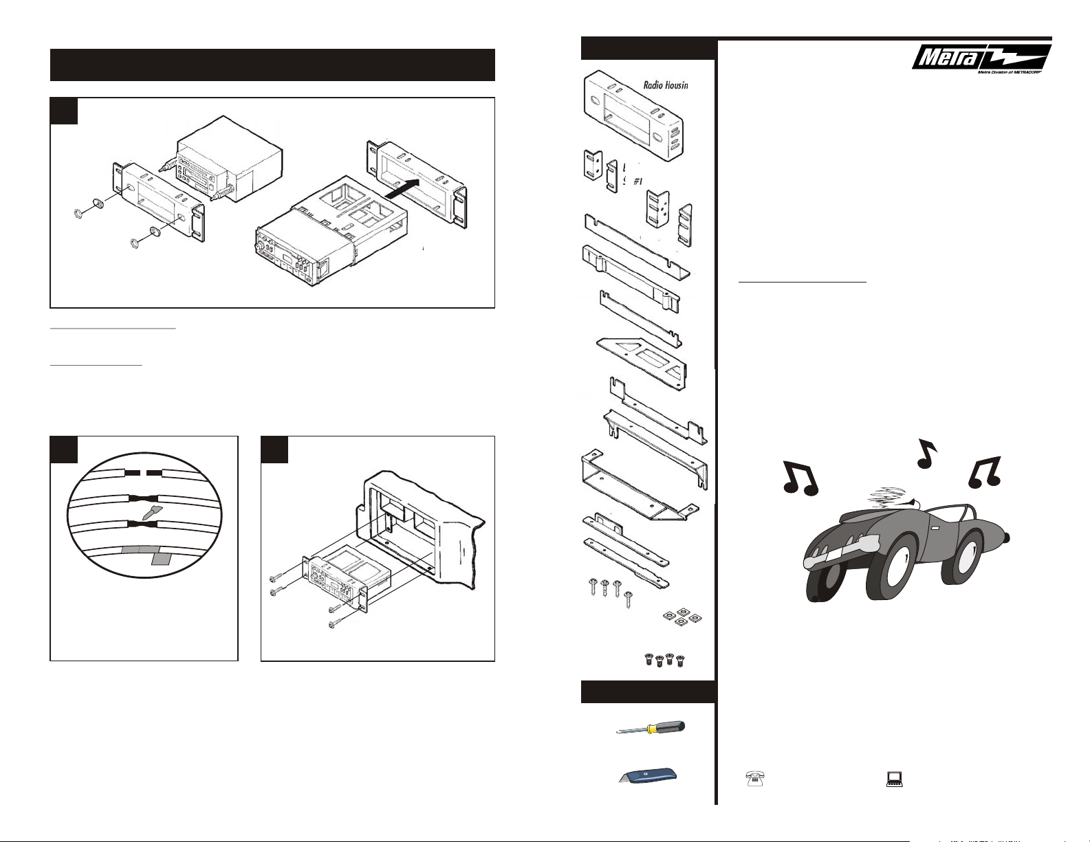
KIT COMPONENTS
Radio Housing
3
Fig. A
Fig. B
2-SHAFT HEAD UNITS: Attach the Shaft Masks to the Radio Housing. Slide the
aftermarket head unit into the kit and secure with shaft nuts. (see Fig. A)
DIN HEAD UNITS: Using the scored lines on the back of the Radio Housing as a guide, cut
and remove the shaft supports. Slide the DIN cage into the kit and secure by bending the metal
locking tabs down. Slide the aftermarket head unit into the cage until secure. (see Fig. B)
4 5
A
B
Bracket
Set #1
Bracket
Set #3
Bracket #6
Bracket
Set #4
Bracket
Set #5
Bracket
Set #2
99-5500
INSTALLATION
INSTRUCTIONS
APPLICATIONS
FORD/MERCURY 1979-91
(SEE INSIDE FOR SPECIFIC APPLICATIONS)
C
D
A) Strip wire ends back ½"
B) Twist ends together
C) Solder
D) Tape
Locate the factory wiring harness in the
dash. Metra recommends using the
proper mating adaptor and making
connections as shown. (Isolate and
individually tape off the ends of any
unused wires to prevent electrical short
circuit).
7
Re-connect the battery terminal and test the unit
for proper operation. Mount the radio/kit
assembly to the sub-dash with those screws
previously removed in step #1.
rev. 030701
Bracket
Set #7
(4) #8 x ¾"
Hex-head Screws
(4) Nuts
(4) 3/8" Phillips
Flat-head Screws
TOOLS REQUIRED
Phillips screwdriver
Cutting tool
1-800-221-0932 www.metraonline.com
© COPYRIGHT 2001 METRA ELECTRONICS CORPORATION
Page 2
TABLE OF CONTENTS
FORD Tempo / MERCURY Topaz 1985-88
CAR PAGE
FORD
Aerostar 1985-91................. 1
Bronco 1980-86................... 2
Bronco II 1983-88................ 2
Crown Victoria 1984-90........3
Econoline 1975-91............... 3
Escort 1985-90.....................4
EXP 1985-90........................3
LTD 1983-86........................ 4
Mustang 1985-86................. 5
Pickup 1980-86.................... 2
Ranger 1983-88................... 2
If a 2-shaft head unit is being installed, be sure the studs on the Brackets fit into
the SMALL ROUND HOLES in the Housing during the kit assembly in step #2.
If a DIN head unit is being installed, be sure the studs on the Brackets fit into
the SLOTTED HOLES in the Housing during the kit assembly in step #2.
CAR PAGE
FORD (cont).
Taurus 1986-89.................... 5
Tempo 1985-88.................... 6
Thunderbird 1985-88........... 6
MERCURY
Capri 1985-86...................... 5
Cougar 1985-88................... 6
Grand Marquis 1984-90....... 3
Lynx 1985-90....................... 4
Marquis 1983-86.................. 4
Sable 1986-89......................5
Topaz 1985-88..................... 6
FORD Aerostar 1985-91
1
Disconnect the negative battery terminal to
prevent an accidental short circuit. Remove
the ashtray by disengaging the release tab
at the rear of the ashtray bracket. Remove
(2) screws from the lower edge of the dash
trim bezel. Unsnap the top edge of the bezel
and remove. Remove (4) screws securing
the factory head unit and disconnect the
wiring.
2
Mount Bracket Set #3 to the Radio
Housing with (4) 3/8" Phillips Flat-head
Screws and (4) Nuts supplied. Skip to the
Installation Instructions for ALL VEHICLES
on Page #7.
FORD Thunderbird / MERCURY Cougar 1985-88
1
Disconnect the negative battery terminal to
prevent an accidental short circuit. Remove
(2) screws from the bottom of the radio trim
bezel. Pry down on the (2) tabs located at
the top of the radio trim bezel and remove
the bezel. Remove (4) screws securing the
factory head unit and disconnect the wiring.
1
2
Mount Bracket Set #1 to the Radio
Housing with (4) 3/8" Phillips Flat-head
Screws and (4) Nuts supplied. Skip to the
Installation Instructions for ALL VEHICLES
on Page #7.
1
Disconnect the negative battery terminal to
prevent an accidental short circuit. Open
the ashtray and remove (2) screws exposed
in the ashtray cavity. Remove (2) screws
from the top of the dash trim bezel. Remove
the bezel. Remove (4) screws securing the
factory head unit and disconnect the wiring.
2
Mount Bracket Set #1 to the Radio
Housing with (4) 3/8" Phillips Flat-head
Screws and (4) Nuts supplied. Skip to the
Installation Instructions for ALL VEHICLES
on Page #7.
6
Page 3

FORD Mustang / MERCURY Capri 1985-86
FORD Bronco / Pickup 1980-86
1
Disconnect the negative battery terminal to
prevent an accidental short circuit. Open
the console storage box and remove (4)
screws exposed in the bottom of the box.
Remove (2) screws securing the emergency
brake trim and remove the trim. Unclip the
gear shifter trim and remove. Open the
ashtray and remove (2) screws exposed.
Remove (4) screws under the ashtray
opening. Remove the console. Remove (3)
screws securing the factory head unit and
disconnect the wiring.
FORD Taurus / MERCURY Sable 1986-89
2
Mount Bracket #6 to the Radio Housing
with (2) 3/8" Phillips Flat-head Screws and
(2) Nuts supplied. Skip to the Installation
Instructions for ALL VEHICLES on Page #7.
1
Disconnect the negative battery terminal to
prevent an accidental short circuit. Remove
(2) screws from the top edge of the dash trim
bezel. Pull out on the top of the bezel,
unhook the base and remove the bezel. If a
factory head unit is NOT present, scribe the
(4) mounting holes and radio opening onto
the bezel. Drill the holes, cut the opening
and place (4) U-clips over the mounting
positions.
FORD Bronco II / Ranger 1983-88
2
Mount Bracket Set #5 to the Radio
Housing with (4) 3/8" Phillips Flat-head
Screws and (4) Nuts supplied. Skip to the
Installation Instructions for ALL VEHICLES
on Page #7.
21
1
Disconnect the negative battery terminal to
prevent an accidental short circuit. Remove
(2) screws from the bottom of the radio trim
bezel. Pry out on the edges of the bezel and
remove. Remove (4) screws securing the
factory head unit and disconnect the wiring.
5
2
Mount Bracket Set #7 to the Radio
Housing with (4) 3/8" Phillips Flat-head
Screws and (4) Nuts supplied. Skip to the
Installation Instructions for ALL VEHICLES
on Page #7.
Disconnect the negative battery terminal to
prevent an accidental short circuit. Remove
(2) screws from the top edge of the dash trim
bezel. Remove the light switch knob,
cigarette lighter and ashtray. Unsnap the
black trim molding under the dash trim bezel
and remove (2) screws exposed. Remove
the bezel. Remove (4) screws securing the
factory head unit and disconnect the wiring.
Mount Bracket Set #1 to the Radio
Housing with (4) 3/8" Phillips Flat-head
Screws and (4) Nuts supplied. Skip to the
Installation Instructions for ALL VEHICLES
on Page #7.
2
Page 4

FORD Crown Victoria 1984-90
MERCURY Grand Marquis 1984-90
1
Disconnect the negative battery terminal to
prevent an accidental short circuit. Open
the ashtray and remove (2) screws exposed.
Unclip the dash trim bezel and remove the
radio dummy plate. Place (4) U-nuts over
the mounting positions in the sub-dash.
2
Mount Bracket Set #1 to the Radio
Housing with (4) 3/8" Phillips Flat-head
Screws and (4) Nuts supplied. Skip to the
Installation Instructions for ALL VEHICLES
on Page #7.
FORD Escort / MERCURY Lynx 1985-90
Disconnect the negative battery terminal to
prevent an accidental short circuit. Remove
(4) screws from the top edge of the radio trim
bezel. Remove (2) screws from the bottom
edge of the radio trim bezel. Remove the
climate control knobs and unclip the bezel.
Remove (4) screws securing the factory
head unit and disconnect the wiring.
21
Mount Bracket Set #2 to the Radio
Housing with (4) 3/8" Phillips Flat-head
Screws and (4) Nuts supplied. Skip to the
Installation Instructions for ALL VEHICLES
on Page #7.
FORD Econoline 1975-91
1
Disconnect the negative battery terminal to
prevent an accidental short circuit. Remove
(3) screws from the lower edge of the dash
trim bezel. Remove (2) screws above the
radio opening. Unsnap the right corner of
the dash trim bezel, disconnect the cigarette
lighter wiring and remove the bezel.
Remove the screws securing the factory
head unit and disconnect the wiring.
3
2
Mount Bracket Set #4 to the Radio
Housing with (4) 3/8" Phillips Flat-head
Screws and (4) Nuts supplied. Skip to the
Installation Instructions for ALL VEHICLES
on Page #7.
FORD LTD / MERCURY Marquis 1983-86
1
Disconnect the negative battery terminal to
prevent an accidental short circuit. Remove
the ashtray and climate control knobs.
Remove (2) screws from the bottom of the
dash trim bezel. Lift up on the bottom of the
bezel and remove. Remove the screws
securing the factory head unit and
disconnect the wiring.
2
Mount Bracket Set #1 to the Radio
Housing with (4) 3/8" Phillips Flat-head
Screws and (4) Nuts supplied. Skip to the
Installation Instructions for ALL VEHICLES
on Page #7.
4
 Loading...