

Page 1
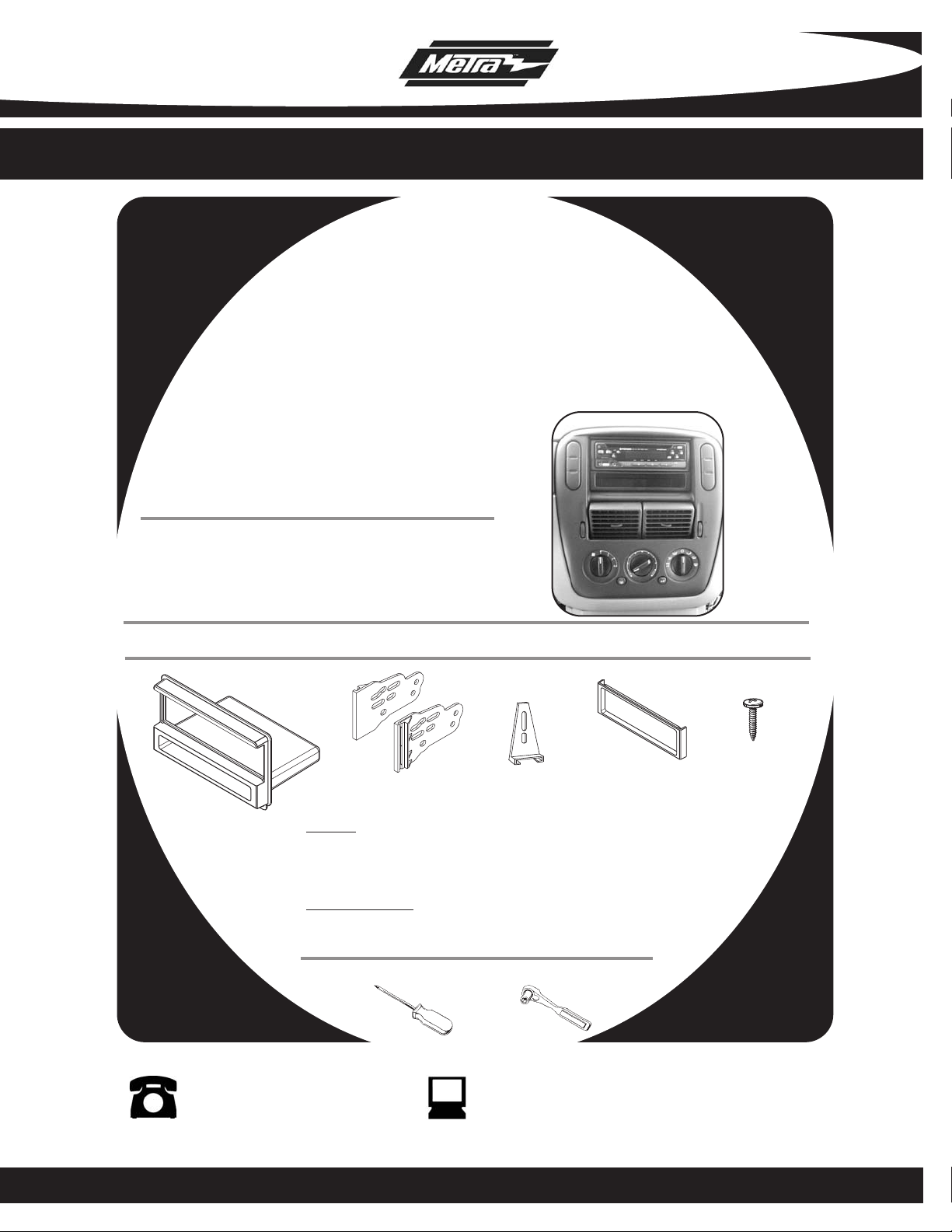
INSTALLATION INSTRUCTIONS FOR PART 99-5026
APPLICA TIONS
Ford Mustang 2001-2004
d Expedition (w/o NAV) 2003-2006
For
Ford Explorer 2002-2005
Lincoln Navigator (w/o NAV) 2003-2006
Lincoln Aviator 2002-2005
Mercury Mountaineer 2002-2005
99-5026
KIT FEATURES
• DIN head unit provision with pocket
• ISO DIN head unit provision with pocket
KIT COMPONENTS
A) Radio Housing B) ISO Brackets C) Rear Support Bracket D) ISO Trimplate E) (1) #8 X 3/8” Phillips Truss Head Screw
A
C
D
B
WIRING AND ANTENNA CONNECTIONS (Sold Separately)
Harness
• 70-5519 - Ford amplified harness 1998-08
• 70-5520 - Ford harness 2003-up
• 70-5521 - Ford amplified harness 2003-up
• 70-1771 - Ford harness 1998-up
Antenna Adapter:
• Not required
:
TOOLS REQUIRED:
Phillips Screwdriver • Socket wrench
E
1-800-221-0932 www.metraonline.com
© COPYRIGHT 2004-2009 METRA ELECTRONICS CORPORATION
Page 2

99-5026
KNOWLEDGE IS POWER
Enhance your installation and fabrication skills by
enrolling in the most recognized and respected
mobile electronics school in our industry.
Log onto www.installerinstitute.com or call
800-354-6782 for more information and take
steps toward a better tomorrow.
TABLE OF CONTENTS
Dash Disassembly . . . . . . . . . . . . . . . . . . . . . . . . . . . . . . . . . . 1-5
Kit Assembly . . . . . . . . . . . . . . . . . . . . . . . . . . . . . . . . . . . . . 6-7
Final Assembly . . . . . . . . . . . . . . . . . . . . . . . . . . . . . . . . . . . . . . . 8
Page 3
99-5026
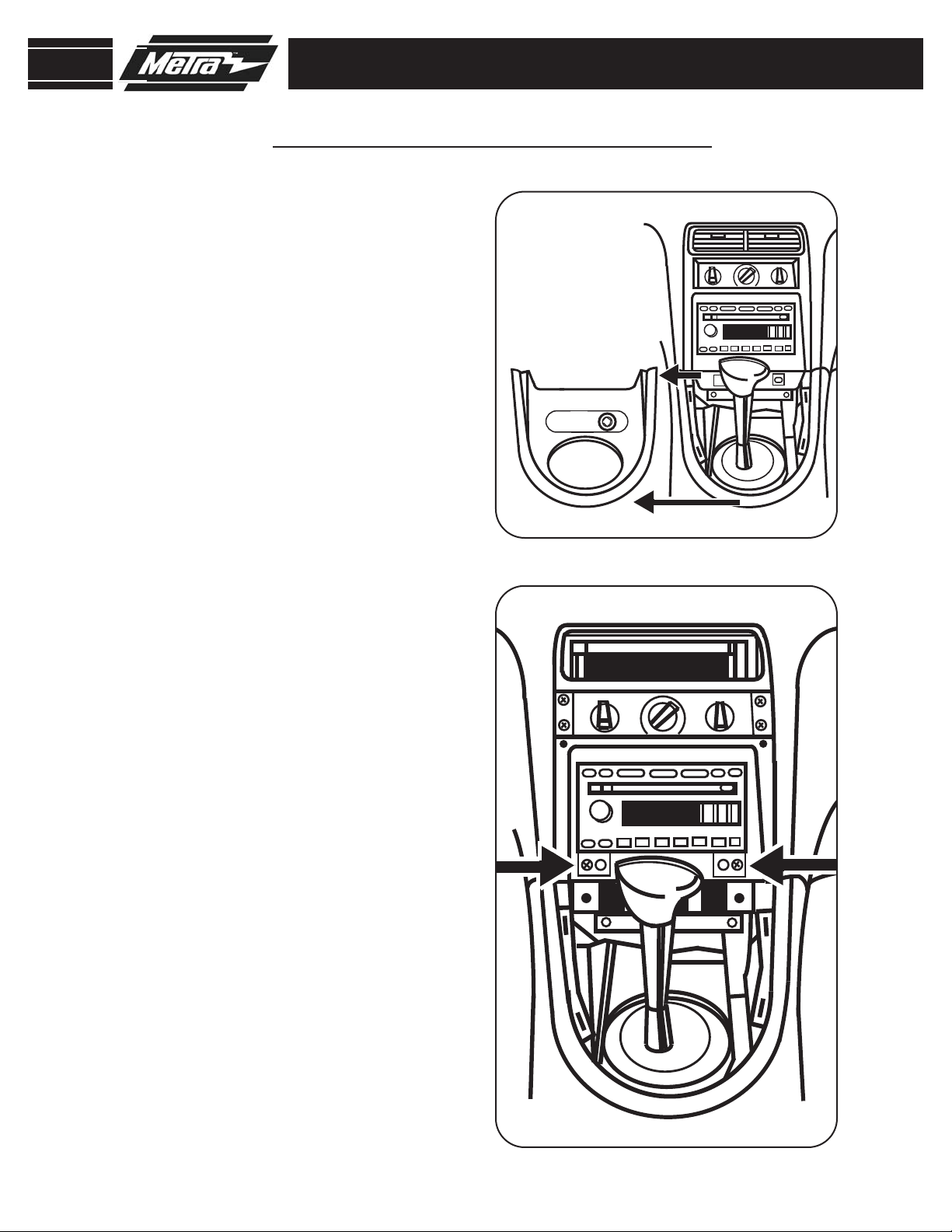
FORD MUSTANG 2001-2004
Disconnect the negative battery
1
terminal to prevent an accidental
short circuit.
2
Unclip and remove shift lever trim
panel.
Unclip and remove the entire panel
3
surrounding the radio and climate
controls including the vents.
(Figure B)
(Figure A)
DASH DISASSEMBLY
A
4
Remove (2) 9/32” screws securing
radio.
(Figure B)
B
1
Page 4
99-5026
DASH DISASSEMBLY
FORD EXPEDITION 2003-2006
Disconnect the negative battery
1
terminal to prevent an accidental
short circuit.
2
Remove (2) 9/32” screws from above
instrument cluster.
Unclip and remove entire panel sur-
3
rounding radio, climate controls, and
instrument cluster.
4
Remove (2) 9/32” screws securing
radio.
B
(Figure A)
(Figure B)
A
2
Page 5
99-5026
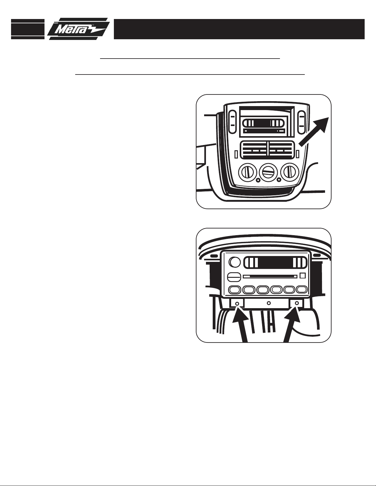
FORD EXPLORER 2002-2005
MERCURY MOUNTAINEER 2002-2005
Disconnect the negative battery ter-
1
minal to prevent an accidental short
circuit.
2
Unclip and remove entire panel surrounding radio including climate controls and vents.
Remove (2) 9/32” screws securing
3
radio.
(Figure B)
(Figure A)
DASH DISASSEMBLY
A
B
3
Page 6
99-5026
INSIDE CENTER CONSOLE
TOP VIEW
TOP OF SHIFTER TRIM PANEL
5
4
7
7
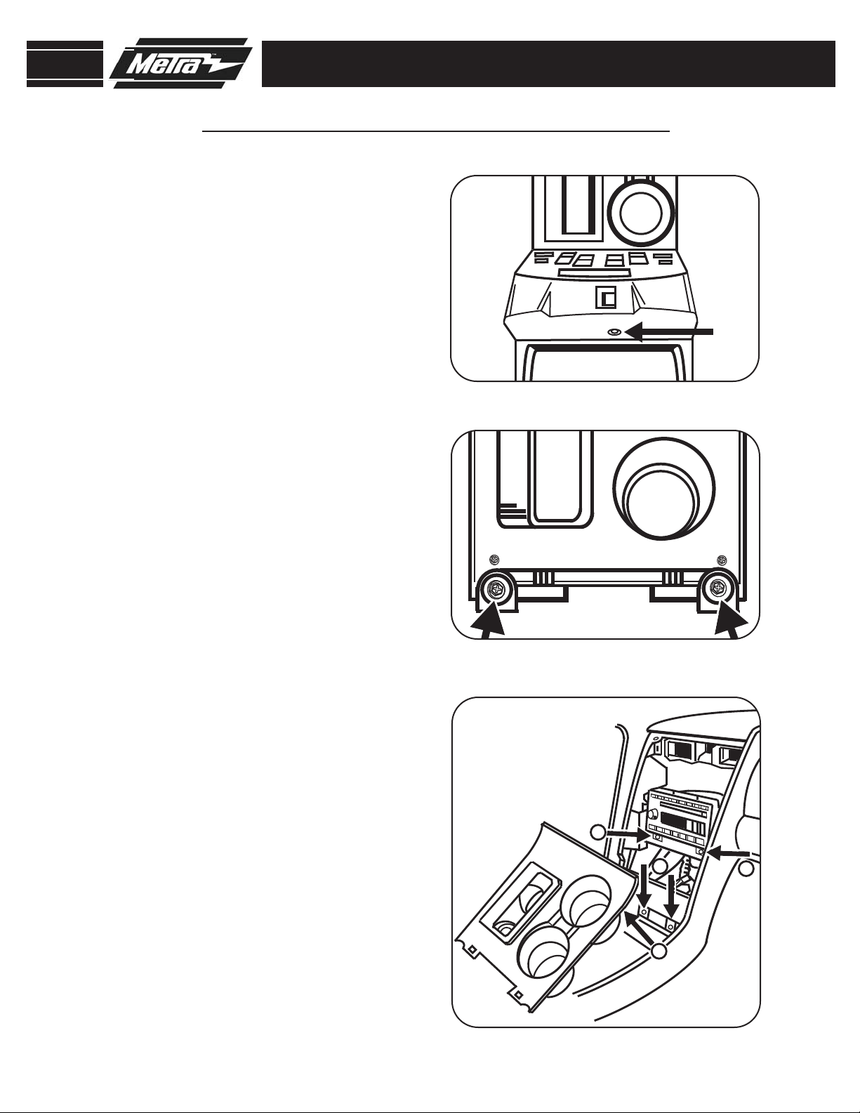
LINCOLN NAVIGATOR 2003-2006
Disconnect the negative battery ter-
1
minal to prevent an accidental short
circuit.
2
Open center console and remove (1)
push pin from back of power window
switch panel.
Unclip and remove panel.
3
Remove (2) 9/32” screws exposed
4
on shifter panel then unclip and
move shifter panel off to side.
(Figure B,C)
(Figure A)
DASH DISASSEMBLY
A
B
5
Remove (2) 9/32” screws exposed
under ashtray assembly.
6
Unclip and remove entire panel sur-
(Figure C)
rounding climate controls and radio.
7
Remove (2) 9/32” screws securing
radio.
(Figure C)
C
4
Page 7

99-5026
105.9
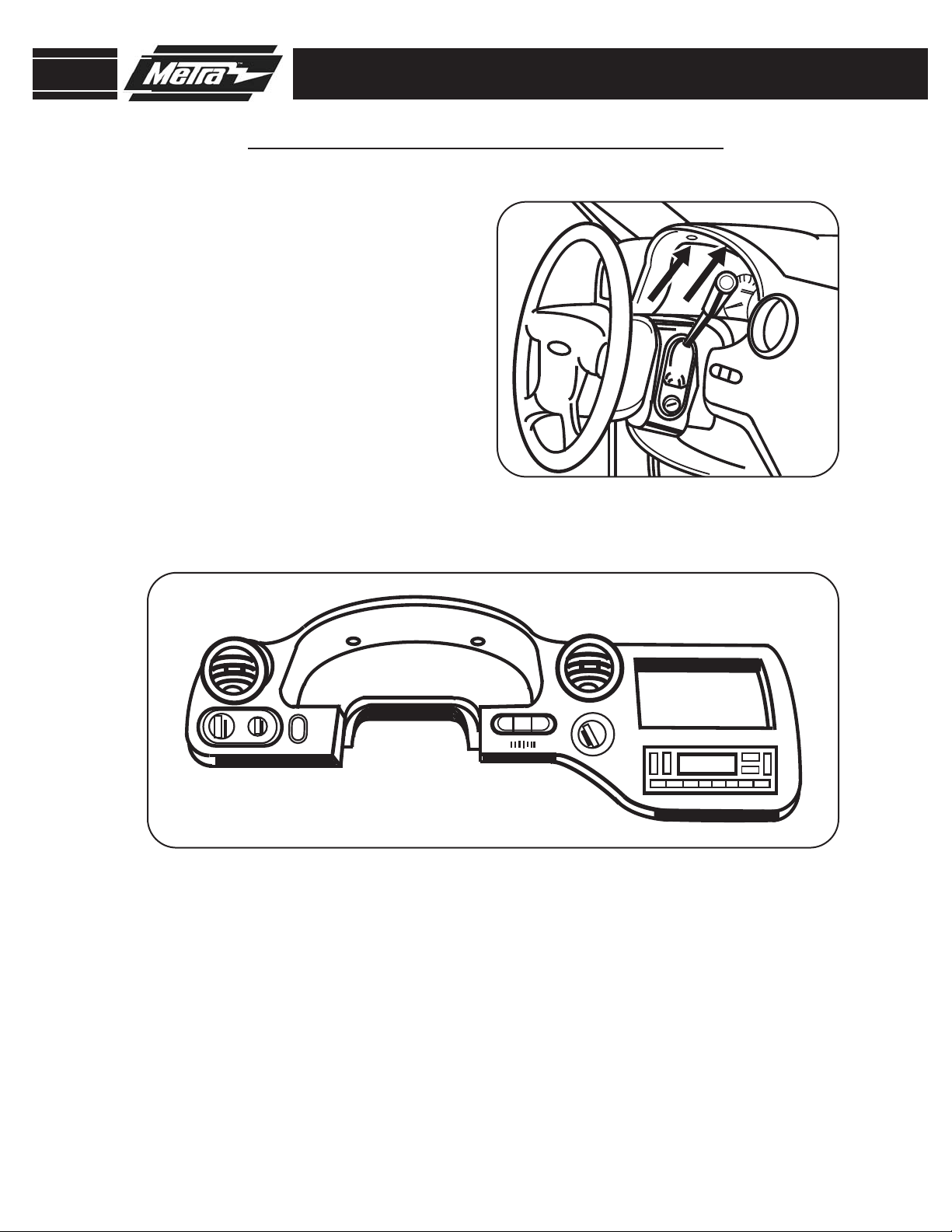
LINCOLN AVIATOR 2003-2005
Disconnect the negative battery ter-
1
minal to prevent an accidental short
circuit.
2
Unclip and remove vent panel above
radio on top of dashboard.
Remove (2) 9/32” screws exposed
3
under panel removed in step 1.
(Figure B)
Unclip and remove panel around
4
radio with door in it.
(Figure C)
DASH DISASSEMBLY
A
(Figure A)
B
Unclip and remove vents below
5
radio.
Remove (2) 9/32” screws securing
6
radio.
Figure D)
(Figure E)
E
C
D
5
Page 8

99-5026
REAR VIEW HEAD UNIT
REAR SUPPORT BRACKET
KIT ASSEMBLY
DIN HEAD UNIT PROVISION WITH POCKET
A
Slide the DIN cage into the housing
1
and secure by bending the metal
locking tabs down. (
Slide the aftermarket head unit into
2
the cage and secure. Snap the trimplate into the radio housing.
Figure B)
(
Thread the rear support bracket onto
3
the back of the head unit (or cage)
and secure with the mounting nut
supplied. (
Figure C)
Figure A)
B
NOTE:
4
Navigator DIN head and ISO kit
assemblies, you must cut the Rear
Support Bracket for clearance.
(
On Ford Expedition and Lincoln
Figure D)
D
C
6
Page 9

99-5026
REAR VIEW - HEAD UNIT
REAR SUPPORT BRACKET
KIT ASSEMBLY
ISO DIN HEAD UNIT PROVISION WITH POCKET
A
Snap the trim plate into the radio
1
housing. Attach the ISO brackets to
the inner lip of the housing. (
Slide the head unit/bracket assembly
2
into the radio opening and align the
holes in the head unit with the holes
in the ISO brackets and mount the
unit to the brackets with the screws
supplied with the unit. (
Thread the rear support bracket onto
3
the back of the head unit (or cage)
and secure with the mounting nut
supplied. (
Figure C)
Figure A)
Figure B)
B
NOTE:
4
Navigator DIN head and ISO kit
assemblies, you must cut the Rear
Support Bracket for clearance.
(
On Ford Expedition and Lincoln
Figure D)
D
C
7
Page 10

99-5026
FINAL ASSEMBLY
FINAL ASSEMBLY
Locate the factory wiring harness in the dash and make the connection as shown.
1
Metra recomends using the proper mating adapter and making the connections as
shown. (Isolate and individually tape off the ends of any unused wires to prevent
electrical short circuit.)
Re-connect the negative battery terminal and test the unit for proper operation.
2
3
Reassemble radio and dash assemblies in reverse order of disassembly.
FINAL WIRING CONNECTIONS
Make wiring connections using the EIA color code chart shown below and the instructions included with the head
unit. Metra recommends making connections as shown below; Strip, Splice, Solder, Tape. Isolate and individually
tape off ends of any unused wires to prevent electrical short circuit.
A
B
C
D
A) Strip wire ends back 1/2"
B)
C) Solder
D) Tape
Twist ends together
METRA / EIA WIRING CODE
12V Ignition / Acc . . . Red
12V Batt / Memory . . Yellow
Ground . . . . . . . . . . . Black*
Power Antenna . . . . . Blue
Amp Turn-On . . . . . . Blue / White
Right Front (+) . . . . . Gray
Right Front (-) . . . . . . Gray / Black
Left Front (+) . . . . . . White
Left Front (-). . . . . . . White / Black
Right Rear (+). . . . . . Violet
Amp Ground . . . . . . . Black / White
Illumination. . . . . . . . Orange
Dimmer . . . . . . . . . . Orange / White
*NOTE: When Black a wire is not present, ground radio to vehicle chassis.
All colors may not be present on all leads due to manufacturer’s specifications.
Right Rear (-) . . . . . . Violet / Black
Left Rear (+). . . . . . . Green
Left Rear (-) . . . . . . . Green / Black
8
Page 11

INSTRUCCIONES DE INSTALACIÓ N PARA LA PIEZA 99-5026
e
stoadoaed
etubo
APLICACIONES
Ford Mustang 2001-2004
Ford Expedition (w/o NAV) 2003-2006
Ford Explorer 2002-2005
Lincoln Navigator (w/o NAV) 2003-2006
Lincoln Aviator 2002-2005
Mercury Mountaineer 2002-2005
99-5026
CARACTERÍSTICAS DEL KIT
• Accesorio para unidades centrales DIN con bolsillo
• Accesorio para unidades centrales DIN ISO con bolsillo
COMPONENTES DEL KIT
A) Alojamiento del radio B) Soportes ISO C) Soporte de apoyo trasero D) Placa de terminación ISO
E) (1) tornillo de cabeza rebajada Phillips n.° 8 de 3/8 in
C
D
B
A
CONEXIONES DE CABLEADO Y ANTENA (se venden por separado)
Arnés:
• Arnés amplificado de Ford 70-5519 1998-08
• Arnés de Ford 70-5520 2003 y modelos posteriores
• Arnés amplificado de Ford 70-5521 2003 y modelos posteriores
• Arnés de Ford 70-1771 1998 y modelos posteriores
Adaptador de antena:
• Opcional
HERRAMIENTAS REQUERIDAS:
Destornillador Phillips • Llave de tubo
E
1-800-221-0932 www.metraonline.com
© COPYRIGHT 2004-2009 METRA ELECTRONICS CORPORATION
Page 12

99-5026
I NDICE
Desmontaje del tablero . . . . . . . . . . . . . . . . . . . . . . . . . . . . . . 1-5
Montaje del kit . . . . . . . . . . . . . . . . . . . . . . . . . . . . . . . . . . . . 6-7
Montaje final . . . . . . . . . . . . . . . . . . . . . . . . . . . . . . . . . . . . . . . . 8
Conocimiento es Poder
Convierta su hobby en una carrera en Installer Institute,
el líder educativo de la industria de dispositivos
electrónicos portátiles.
Regístrese en www.installerinstitute.com o llame al
800-354-6782 para obtener más información y empiece
su nueva carrera hoy mismo.
Page 13

99-5026
FORD MUSTANG 2001-2004
1
Desconecte el terminal negativo de
la batería, a fin de evitar un cortocircuito accidental.
2
Desenganche y retire el panel de terminación de la palanca de velocidades. (Figura A)
3
Desenganche y retire todo el panel
que rodea el radio y los controles de
clima, incluidas las rejillas de ventilación. (Figura B)
DESMONTAJE DEL TABLERO
A
4
Retire (2) tornillos de 9/32 in que
sujetan el radio. (Figura B)
B
1
Page 14

99-5026
FORD EXPEDITION 2003-2006
1
Desconecte el terminal negativo de
la batería, a fin de evitar un cortocircuito accidental.
2
Retire (2) tornillos de 9/32 in que se
encuentran arriba del grupo de
instrumentos. (Figura A)
3
Desenganche y retire todo el panel
que se encuentra alrededor del
radio, los controles de clima y el
grupo de instrumentos. (Figura B)
4
Retire (2) tornillos de 9/32 in que
sujetan el radio.
DESMONTAJE DEL TABLERO
A
B
2
Page 15

99-5026
FORD EXPLORER 2002-2005
MERCURY MOUNTAINEER 2002-2005
1
Desconecte el terminal negativo de
la batería, a fin de evitar un cortocircuito accidental.
2
Desenganche y retire todo el panel
que rodea el radio, incluidos los controles de clima y las rejillas de ventilación. (Figura A)
3
Retire (2) tornillos de 9/32 in que
sujetan el radio. (Figura B)
DESMONTAJE DEL TABLERO
A
B
3
Page 16

INSIDE CENTER CONSOLE
TOP VIEW
TOP OF SHIFTER TRIM PANEL
5
4
7
7
99-5026
LINCOLN NAVIGATOR 2003-2006
1
Desconecte el terminal negativo de
la batería, a fin de evitar un cortocircuito accidental.
2
Abra la consola central y retire (1)
tachuela de la parte posterior del
panel de interruptores del alzacristales. (Figura A)
3
Desenganche y retire el panel.
4
Retire (2) tornillos de 9/32 in
expuestos en el panel de la palanca
de velocidades y, luego, desenganche y mueva el panel de la
palanca de velocidades hacia un
lado. (Figuras B, C)
DESMONTAJE DEL TABLERO
A
B
5
Retire (2) tornillos de 9/32 in
expuestos que se encuentran debajo
del conjunto del cenicero. (Figura C)
6
Quite a presión y retire todo el panel
que rodea los controles de clima y el
radio.
7
Retire (2) tornillos de 9/32 in que
sujetan el radio. (Figura C)
C
4
Page 17

105.9
99-5026
LINCOLN AVIATOR 2003-2005
1
Desconecte el terminal negativo de
la batería, a fin de evitar un cortocircuito accidental.
2
Desenganche y retire el panel de la
rejilla de ventilación que se encuentra
arriba del radio, en la parte superior
del tablero. (Figura A)
DESMONTAJE DEL TABLERO
A
3
Retire (2) tornillos de 9/32 in
expuestos que se encuentran debajo
del panel que se retiró en el paso 1.
(Figura B)
4
Desenganche y retire el panel que se
encuentra alrededor del radio con la
puerta incluida. (Figura C)
5
Desenganche y retire las rejillas de
ventilación que se encuentran debajo del radio. (Figura D)
6
Retire (2) tornillos de 9/32 in que
sujetan el radio. (Figura E)
B
C
E
D
5
Page 18

99-5026
MONTAJE DEL KIT
ACCESORIO PARA UNIDADES CENTRALES
DIN CON BOLSILLO
A
Deslice la caja DIN en el alojamiento y
1
sujétela doblando las lengüetas de
cierre de metal hacia abajo. (Figura A)
Deslice la unidad central de posven-
2
ta en la caja y sujétela. Coloque a
presión la placa de terminación en el
alojamiento del radio. (Figura B)
Pase el soporte de apoyo trasero
3
sobre la parte posterior de la unidad
central (o caja) y sujételo con la
tuerca de montaje suministrada.
(Figura C)
B
4
NOTA: Para los conjuntos de centrales
DIN y de kit ISO de los modelos Ford
Expedition y Lincoln Navigator, debe
cortar el soporte de apoyo trasero para
obtener espacio libre. (Figura D)
D
C
REAR VIEW HEAD UNIT
6
REAR SUPPORT BRACKET
Page 19

99-5026
MONTAJE DEL KIT
ACCESORIO PARA UNIDADES CENTRALES DIN
ISO CON BOLSILLO
A
Coloque a presión la placa de termi-
1
nación en
Coloque los soportes ISO en el reborde interno del alojamiento. (Figura A)
Deslice el conjunto de la unidad cen-
2
tral/soporte en la abertura del radio
y alinee los orificios de la unidad
central con los orificios de los
soportes ISO y monte la unidad en
los soportes con los tornillos suministrados con la unidad. (Figura B)
Pase el soporte de apoyo trasero
3
sobre la parte posterior de la unidad
central (o caja) y sujételo con la
tuerca de montaje suministrada.
(Figura C)
el alojamiento del radio.
B
4
NOTA: Para los conjuntos de centrales
DIN y de kit ISO de los modelos Ford
Expedition y Lincoln Navigator, debe
cortar el soporte de apoyo trasero para
obtener espacio libre. (Figura D)
D
C
REAR VIEW - HEAD UNIT
REAR SUPPORT BRACKET
7
Page 20

99-5026
MONTAJE FINAL
MONTAJE FINAL
Ubique el arnés del cableado de fábrica en el tablero y realice las conexiones como
1
se muestra. Metra recomienda usar el adaptador de acoplamiento adecuado y realizar
las conexiones como se muestra. (Aísle y encinte individualmente los extremos de
cualquier cable que no esté en uso a fin de evitar un cortocircuito eléctrico).
Vuelva a conectar el terminal negativo de la batería y pruebe la unidad para veri-
2
ficar que funcione correctamente.
3
Vuelva a montar los conjuntos del radio y tablero en forma inversa al desmontaje.
CONEXIONES DE CABLEADO FINALES
Realice las conexiones de cableado utilizando el cuadro de códigos de colores de la Alianza de industrias electrónicas
(Electronic Industries Alliance, EIA) que se muestra a continuación y las instrucciones incluidas con la unidad central.
Metra recomienda realizar las conexiones como se muestra a con
inte individualmente
los extremos de cualquier cable que no esté en uso, a fin de evitar un cortocircuito eléctrico.
tinuación: Pelar, empalmar, soldar, encintar. Aísle y enc-
A
B
C
D
A) Pele 1/2 in de los extremos de los cables.
B) Tuerza los extremos juntos.
C) Suelde.
D) Encinte.
CODIGO DE CABLEADO DE METRA/EIA
Ignición de 12 V/Acc..............Rojo
Batería de 12 V/memoria.......Amarillo
Conexión a tierra...................Negro*
Antena eléctrica....................Azul
Encendido Amp.....................Azul/blanco
Conexión a tierra Amp...........Negro/blanco
Iluminación............................Naranja
Atenuador..............................Naranja/blanco
Parte delantera derecha (+).............Gris
Parte delantera derecha (-)..............Gris/negro
Parte delantera izquierda (+)............Blanco
Parte delantera izquierda (-).............Blanco/negro
Parte trasera derecha (+)..................Violeta
Parte trasera derecha (-)...................Violeta/negro
Parte trasera izquierda (+)................Verde
Parte trasera izquierda (-).................Verde/negro
*NOTA: Cuando no haya un cable negro, conecte a tierra el radio con el chasis del vehículo.
Es posible que no se encuentren todos los colores en todos los conductores como consecuencia de las especi-
ficaciones del fabricante.
8
 Loading...