

Page 1
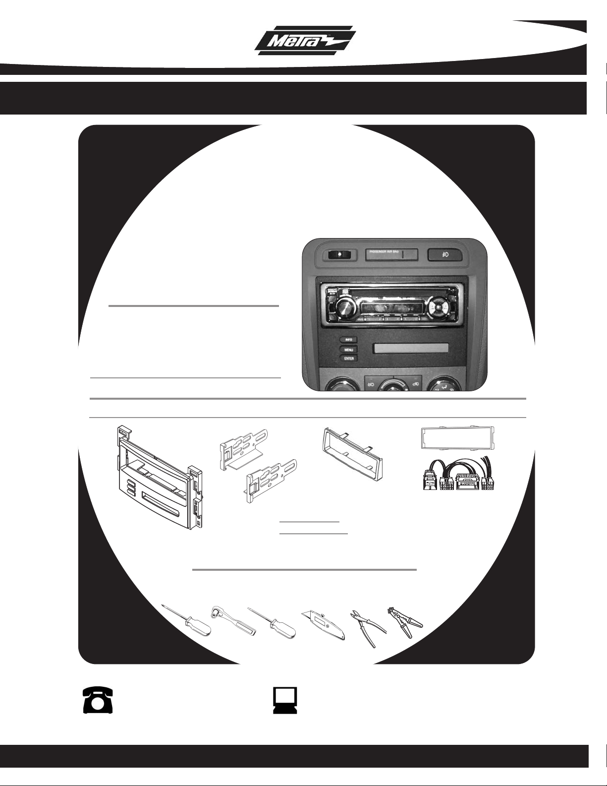
INSTALLATION INSTRUCTIONS FOR PART 99-3303
APPLICATIONS
Chevrolet Cobalt 2005-2006
Chevrolet Malibu 2004-2007
Chevrolet Malibu Classic 2008
Pontiac G6 2005-2009
99-3303
KIT FEATURES
• DIN Head Unit Provision with
Driver Information Center (DIC)
• ISO DIN Head Unit Provision with
Driver Information Center (DIC)
KIT COMPONENTS
A) Radio Housing • B) ISO Brackets • C) ISO Trim Plate • D) DIN Spacer • E) Wire Harness
D
A
C
B
WIRING AND ANTENNA CONNECTIONS (Sold Separately)
Wiring Harness: Included
Antenne Adapter:
• 40-GM10 - GM antenna adapter 1988-up
TOOLS REQUIRED:
Phillips Screwdriver • Socket Wrench • Flat Blade Screwdriver • Cutting Tool (Cobalt Only)
Wire Cutters • Wire Strippers
E
1-800-221-0932 www.metraonline.com
© COPYRIGHT 2004-2009 METRA ELECTRONICS CORPORATION
Page 2

99-3303
K
NOWLEDGE IS POWER
Enhance your installation and fabrication skills by
enrolling in the most recognized and respected
mobile electronics school in our industry.
Log onto www.installerinstitute.com or call
800-354-6782 for more information and take
steps toward a better tomorrow.
•
Dash Disassembly
- Chevrolet Malibu 2004-2007 . . . . . . . . . . . . . . . . . . . . . . . . . . . . . 1,2
- Chevrolet Malibu Classic 2008. . . . . . . . . . . . . . . . . . . . . . . . . . . . 1,2
- Pontiac G6 2005-2009 . . . . . . . . . . . . . . . . . . . . . . . . . . . . . . . . . . . 3
- Chevrolet Cobalt 2005-2006 . . . . . . . . . . . . . . . . . . . . . . . . . . . . . . 4
•
Kit Assembly
- DIN Head Unit Provision with Pocket . . . . . . . . . . . . . . . . . . . . . . . . 5
- ISO Head Unit Provision with Pocket . . . . . . . . . . . . . . . . . . . . . . . . 6
•
Final Assembly . . . . . . . . . . . . . . . . . . . . . . . . . . . . . . . . . . . . . . . . . 7
•
Operation of the 99-3303 . . . . . . . . . . . . . . . . . . . . . . . . . . . . . . . . . 8
TABLE OF CONTENTS
Page 3
99-3303
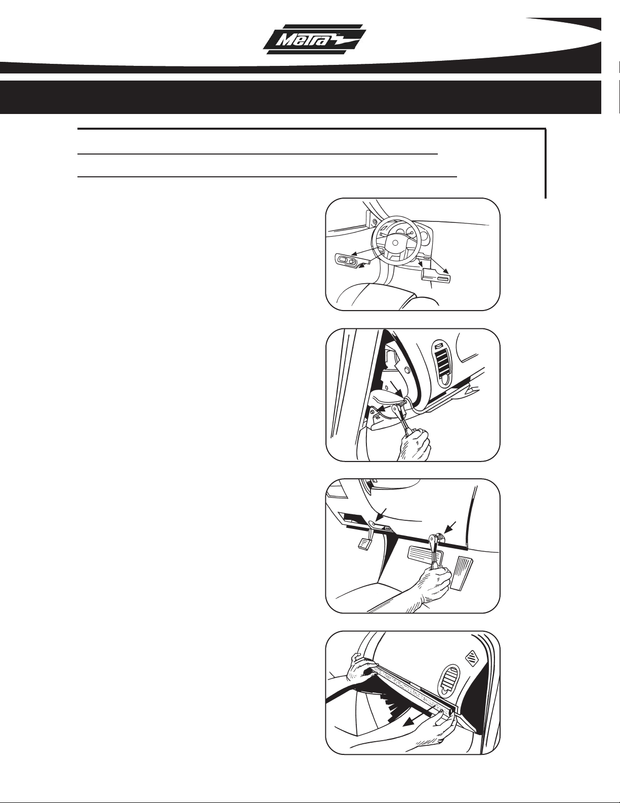
CHEVROLET MALIBU 2004-2007
CHEVROLET MALIBU CLASSIC 2008
A
Disconnect the negative battery terminal
1
to prevent an accidental short circuit.
2
Unclip and remove wood grain/painted
trim pieces from both sides of steering
wheel.
3
Unclip and remove side panel from driver’s
side of dash with door open and remove
(2) 7MM screws.
Remove (2) 7MM screws from bottom edge of
4
panel below steering wheel. Unclip panel and
let hang. It is not necessary to completely
remove panel.
(Figure A)
B
(Figure B)
(Figure C)
DASH DISASSEMBLY
5
Unclip and remove wood grain/painted
trim pieces from above glove box.
(Figure D)
C
D
1
Page 4
99-3303
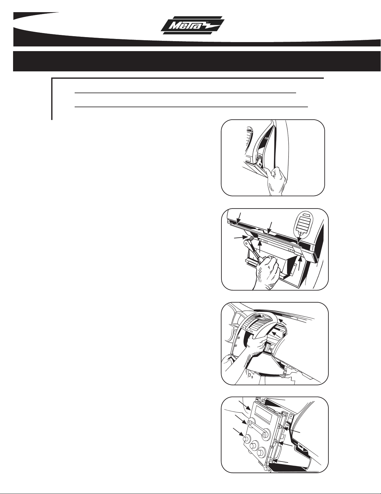
CHEVROLET MALIBU 2004-2007
CHEVROLET MALIBU CLASSIC 2008
E
Unclip and remove side panel from
6
passenger side of dash with door open
and remove (2) 7 MM screws from behind
panel. (Figure E)
7
Remove (2) 7 MM screws from bottom of
glove box then open box and squeeze
sides together to open further and remove
the remaining (4) 7MM screws. Unclip the
black vent cover under the glove box then
unclip and remove entire glove box
assembly.
(Figure F)
F
DASH DISASSEMBLY
8
Unclip and remove trim panel surrounding
radio and climate controls.
9
Remove (4) 7MM screws from the radio
and (2) 7MM screws from climate control
to remove radio. (Figure H)
(Figure G)
G
H
2
Page 5
99-3303
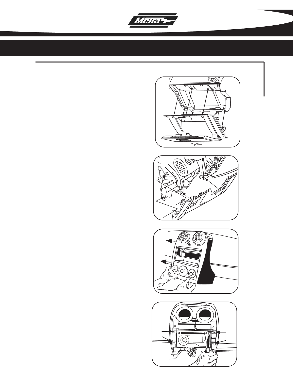
PONTIAC G6 2005-2009
1
Disconnect the negative battery terminal to
prevent an accidental short circuit.
Open glove box and remove (6) screws from
2
outer edge then unclip and remove box.
(Figure A)
Remove (4) screws from panel below steer-
3
ing column and unclip and remove panel.
(Figure B)
Unclip and remove center panel surrounding
4
radio and A/C controls. (Figure C)
Remove (4) screws and extract radio from
5
sub dash.
(Figure D)
A
DASH DISASSEMBLY
B
3
C
D
Page 6

99-3303
CHEVROLET COBALT 2005-2006
A
Disconnect the negative battery terminal to
1
prevent an accidental short circuit.
Unclip and remove trim panel from above
2
glove box. (Figure A)
3
Unclip upper edge of panel below steering
column and let hang. Not necessary to
remove completely.
4
Unclip and remove small trim panel to right
of ignition switch.
(Figure B)
(Figure C)
B
DASH DISASSEMBLY
5
Unclip and remove trim panel surrounding
radio and climate controls.
Remove (4) 9/32 screws securing radio.
6
(Figure E)
E
(Figure D)
C
D
4
Page 7

99-3303
DIN HEAD UNIT PROVISIONS:
A
Slide the DIN cage into the Radio Housing
1
and secure by bending the metal locking
tabs down.
Slide the aftermarket head unit into the cage
2
and secure.
TE:
NO
A snap-in DIN spacer has been
provided for some applications where
depth is an issue. Snap the spacer in the
housing and slide the DIN cage into the
assembly and secure by bending the
metal locking tabs outward. (Figure C)
(Figure A)
(Figure B)
B
KIT ASSEMBLY
5
C
Page 8

99-3303
ISO DIN HEAD UNIT PROVISIONS:
A
Mount the ISO Brackets to the head unit with
1
the screws supplied with the unit.
Figure A)
(
Slide the head unit into the radio opening
2
until the side clips engage. (Figure B)
3
Snap the Trim plate into the Radio Housing.
(Figure B)
B
KIT ASSEMBLY
6
Page 9

99-3303
FINAL ASSEMBLY
FINAL ASSEMBLY
1
Make wiring connections using the EIA color code chart shown below and the instructions included
with the head unit. Metra recommends making connections as shown below; Strip, Splice, Solder,
Tape. Isolate and individually tape off ends of any unused wires to prevent electrical short circuit.
All connections should be made without the harness plugged into the 99-3303.
A
B
C
D
A) Strip wire ends back 1/2"
B) Twist ends together
C) Solder
D) Tape
METRA / EIA WIRING CODE
12V Ignition / Acc . . . Red
12V Batt / Memory . . Yellow
Ground . . . . . . . . . . . Black*
Power Antenna . . . . . Blue
Amp Turn-On . . . . . . Blue / White
Amp Ground . . . . . . . Black / White
Illumination. . . . . . . . Orange
Right Front (+) . . . . . Gray
Right Front (-) . . . . . . Gray / Black
Left Front (+) . . . . . . White
Left Front (-) . . . . . . . White / Black
Right Rear (+). . . . . . Violet
Right Rear (-) . . . . . . Violet / Black
Left Rear (+). . . . . . . Green
Dimmer . . . . . . . . . . Orange / White
*NOTE: When Black a wire is not present, ground radio to vehicle chassis.
All colors may not be present on all leads due to manufacturer’s specifications.
Plug the clear 10 way and 12 way connectors into the back of the 99-3303 housing.
2
3
Connect the Lt. Blue 24 way connector to the factory 24 way harness.
On vehicles equipped with Onstar, connect the Black 12 way connector to the factory
4
12 way harness.
5
Re-connect the negative battery terminal and test the unit for proper operation.
Reassemble dash in reverse order of disassembly.
6
Left Rear (-) . . . . . . . Green / Black
7
Page 10

99-3303
FINAL ASSEMBLY
OPERATION OF THE 99-3303
Settings and Adjustments mode
There is a Settings and Adjustments mode available for the individualized adjustment of the
contrast of the display, brightness of the display and backlighting, OnStar volume, and the button
backlighting color.
Entering the Settings and Adjustments mode
To enter the Settings and Adjustments mode, press the INFO and MENU buttons simultaneously.
When the unit settings and adjustments mode is entered, the LCD will display “Func Sel MENU.”
Selecting a Function to Update
When the unit is in the Settings and Adjustment mode, use the MENU button to select a function to
update. The LCD will display the selected function.
Updating a function
While in the Settings and Adjustment mode, use the INFO and ENTER buttons to adjust the function
selected and displayed on the LCD. See Table 1.0
See Table 1.0
** When OnStar activated, INFO and ENTER can be used to adjust the OnStar volume
without first entering the settings and adjustments mode.
Exiting the unit settings and adjustments mode
The unit will automatically exit the settings and adjustments mode if no buttons are pressed for
about 10 seconds.
Table 1.0
Function LCD Display Description of Operation
LCD Contrast Contrast INF/ENT INFO increases LCD contrast
ENTER decreases LCD contrast
LCD Brightness Bright INF/ENT INFO increases LCD brightness
ENTER decreases LCD brightness
OnStar Volume OnSt Vol INF/ENT INFO increases OnStar Volume
ENTER decreases OnStar Volume
Button Backlighting Color Button Color ENT ENTER changes the button
backlighting between Amber
and Green
8
Page 11

99-3303
NOTES
9
Page 12

INST993303
1-800-221-0932 www.metraonline.com
Rev. 05-27-09 © COPYRIGHT 2004-2009 METRA ELECTRONICS CORPORATION INST99-3303
 Loading...