

Page 1
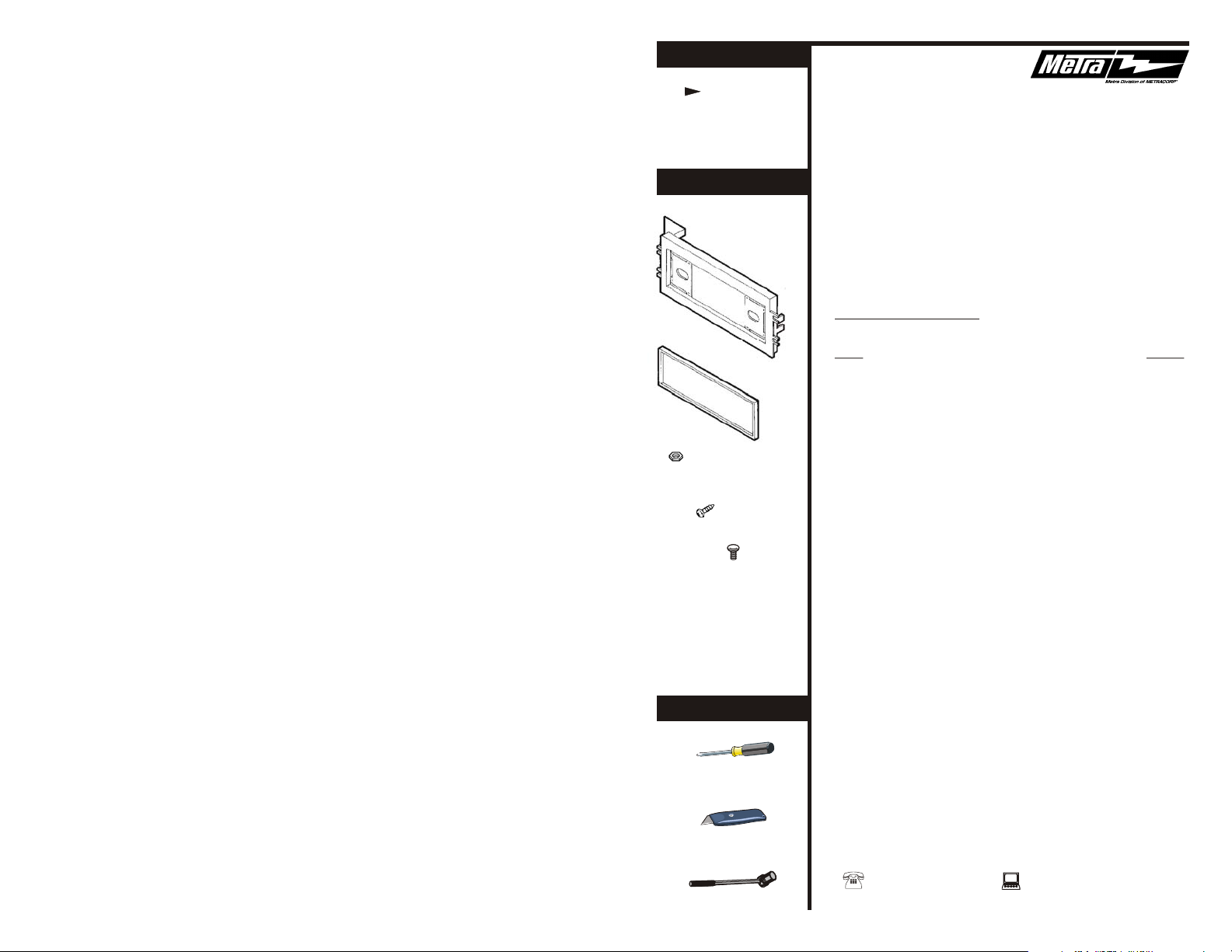
KIT FEATURES
Shaft and
DIN unit
provisions
99-3009
KIT COMPONENTS
Radio Housing
(1) Keps Nut
(1) Phillips
Pan-head Screw
(1) Carriage Bolt
Spacer
INSTALLATION
INSTRUCTIONS
APPLICATIONS
CAR PAGE
CHEVROLET
Camaro 1993-96..........................................................1
PONTIAC
Bonneville 1994-99......................................................1
Firebird 1993...............................................................4
Firebird 1994-02........................................................ 5
Grand Am 1996-98......................................................2
Grand Am 1999-00..................................................... 2
Grand Prix 1994-96.....................................................3
Grand Prix 1997-02.....................................................3
Sunfire 1995-99.......................................................... 4
Trans Am 1993.............................................................4
Trans Am 1994-02....................................................... 5
rev. 090103
TOOLS REQUIRED
Phillips screwdriver
Cutting tool
Socket wrench
1-800-221-0932 www.metraonline.com
© COPYRIGHT 2001 METRA ELECTRONICS CORPORATION
Page 2
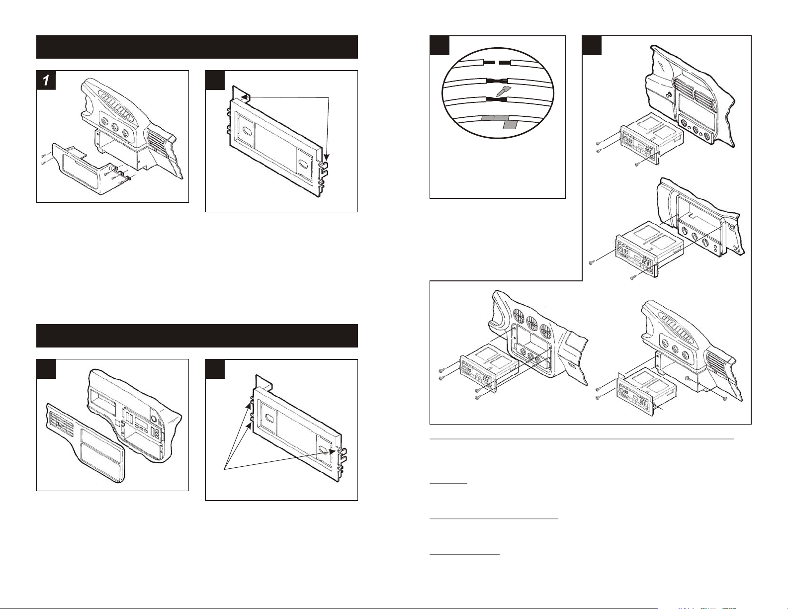
CHEVROLET Camaro 1993-96
4 5
A
1
Disconnect the negative battery terminal to
prevent an accidental short circuit. Remove
(2) Phillips screws from the top of the driver's
side knee bolster. Remove (2) 7mm screws
from the bottom of the knee bolster. Open
the glove box, remove (3) 7mm screws
exposed on the right edge of the radio trim
bezel and remove the bezel. Remove (2)
7mm screws securing the left side of the
factory head unit and (1) 10mm nut securing
the right. Slide the unit from the dash and
disconnect the wiring.
PONTIAC Bonneville 1994-99
2
"A"
Cut and remove all mounting tabs on the
Radio Housing EXCEPT tabs "A". The
mounting tabs can be identified by the
stamped letter on the back of each tab. Skip
to the Installation Instructions for ALL
VEHICLES on Page #5.
B
C
D
A) Strip wire ends back ½"
B) Twist ends together
C) Solder
D) Tape
Locate the factory wiring harness in the
dash. Metra recommends using the
proper mating adaptor and making
connections as shown. (Isolate and
individually tape off the ends of any
unused wires to prevent electrical short
circuit).
Fig. C
Fig. A
Fig. B
"A"
"B"
Fig. D
1
Disconnect the negative battery terminal to
prevent an accidental short circuit. Unclip
the right side of the dash trim bezel. Unclip
the left side of the bezel and remove.
Remove (3) 7mm hex-head screws securing
the factory head unit and disconnect the
wiring.
1
2
"C"
Cut and remove all mounting tabs on the
Radio Housing EXCEPT tabs "C". The
mounting tabs can be identified by the
stamped letter on the back of each tab. Skip
to the Installation Instructions for ALL
VEHICLES on Page #5.
FIREBIRD 1994-99, TRANS AM 1994-99, BONNEVILLE, GRAND AM, GRAND PRIX: Reconnect the battery terminal and test the unit for proper operation. Mount the head unit/kit
assembly to the sub-dash with (3) 7mm hex-head screws previously removed in step #1. (Run
the upper-left screw through the dash plastic for the Grand Prix). (see Fig. A)
SUNFIRE: Re-connect the battery terminal and test the unit for proper operation. Mount the
head unit/kit assembly to the sub-dash with (1) 7mm hex-head screw previously removed in
step #1 ("A") and (1) Phillips Pan-head Screw supplied ("B"). (see Fig. B)
FIREBIRD 1993, TRANS AM 1993: Re-connect the battery terminal and test the unit for
proper operation. Mount the head unit/kit assembly to the sub-dash with (4) 7mm hex-head
screws previously removed in step #1. (see Fig. C)
CAMARO 1993-96: Re-connect the battery terminal and test the unit for proper operation.
Mount the head unit/kit assembly to the sub-dash with (2) 7mm hex-head screws previously
removed in step #1 and (1) Carriage Bolt and (1) Keps Nut supplied. (see Fig. D)
6
Page 3
PONTIAC Trans Am / Firebird 1994-02
PONTIAC Grand Am 1996-98
1
Disconnect the negative battery terminal to
prevent an accidental short circuit. Unclip
the radio trim bezel. Remove (4) 7mm hexhead screws securing the factory head unit
and disconnect the wiring.
ALL VEHICLES
3
Fig. A
2
"C"
Cut and remove all mounting tabs on the
Radio Housing EXCEPT tabs "C". The
mounting tabs can be identified by the
stamped letter on the back of each tab. Skip
to the Installation Instructions for ALL
VEHICLES on Page #5.
*OPTIONAL
1
Disconnect the negative battery terminal to
prevent an accidental short circuit. Remove
(2) Phillips screws from the pocket. Remove
(2) Phillips screws above the instrument
cluster. Unclip the dash trim bezel and
remove. Remove (3) 7mm hex-head
screws securing the factory head unit and
disconnect the wiring.
PONTIAC Grand Am 1999-00
1
2
"C"
Cut and remove all mounting tabs on the
Radio Housing EXCEPT tabs "C". The
mounting tabs can be identified by the
stamped letter on the back of each tab. Skip
to the Installation Instructions for ALL
VEHICLES on Page #5.
2
Fig. B
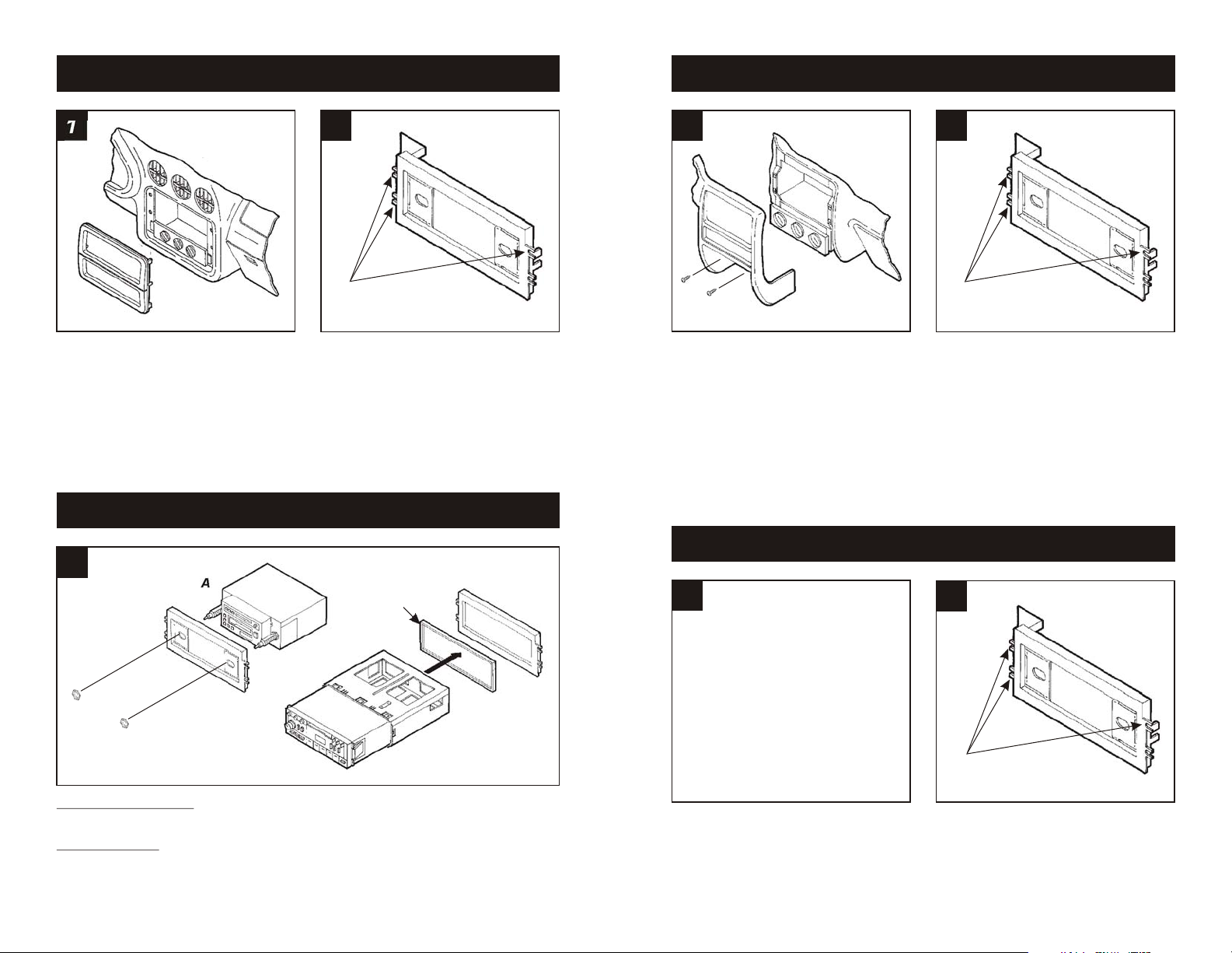
2-SHAFT HEAD UNITS: Slide the aftermarket head unit into the kit and secure with shaft
nuts. (see Fig. A)
DIN HEAD UNITS: Insert the Spacer* into the Radio Housing. Slide the DIN cage into the kit
and secure by bending the metal locking tabs down. Slide the aftermarket head unit into the
cage until secure. (see Fig. B)
5
Illustration not
available when
printed
Disconnect the negative battery terminal to
prevent an accidental short circuit. Unclip
the radio trim bezel. Remove (3) 9/32"
screws securing the factory head unit and
disconnect the wiring.
"C"
Cut and remove all mounting tabs on the
Radio Housing EXCEPT tabs "C". The
mounting tabs can be identified by the
stamped letter on the back of each tab. Skip
to the Installation Instructions for ALL
VEHICLES on Page #5.
2
Page 4

PONTIAC Grand Prix 1994-02
PONTIAC Sunfire 1995-99
1
Disconnect the negative battery terminal to
prevent an accidental short circuit. Using a
small set of pliers, grasp the retaining clip on
the back of the gear shifter handle and
remove the clip. Remove the gear shifter
handle. Unclip the center console and
remove. Remove (2) 7mm hex-head
screws exposed under the climate controls.
Unclip the radio trim bezel and remove.
Remove (2) 7mm hex-head screws securing
the factory head unit and disconnect the
wiring.
PONTIAC Grand Prix 1997-99
2
"C"
Cut and remove all mounting tabs on the
Radio Housing EXCEPT tabs "C". The
mounting tabs can be identified by the
stamped letter on the back of each tab. Skip
to the Installation Instructions for ALL
VEHICLES on Page #5.
1
Disconnect the negative battery terminal to
prevent an accidental short circuit. Open
the glove box and remove (2) Phillips screws
exposed on the right edge of the radio trim
bezel. Unclip the bezel and remove.
Remove (2) 7mm hex-head screws securing
the factory head unit and disconnect the
wiring.
PONTIAC Trans Am / Firebird 1993
2
Fig. A
Fig. B
Cut and remove all mounting tabs on the
Radio Housing EXCEPT tabs "C". (see
Fig. A). Using a dremel tool, cut and remove
the shaded portions of the sub-dash plastic.
This will provide the necessary depth for
installation. (see Fig. B). Skip to the
Installation Instructions for ALL VEHICLES
on Page #5.
"C"
1
Disconnect the negative battery terminal to
prevent an accidental short circuit. Unclip
the entire dash trim bezel. Remove the
screws securing the factory head unit and
disconnect the wiring.
3
2
"C"
Cut and remove all mounting tabs on the
Radio Housing EXCEPT tabs "C". The
mounting tabs can be identified by the
stamped letter on the back of each tab. Skip
to the Installation Instructions for ALL
VEHICLES on Page #5.
1
Disconnect the negative battery terminal to
prevent an accidental short circuit. Unclip
the radio trim bezel. Remove (4) 7mm hexhead screws securing the factory head unit
and disconnect the wiring.
2
"B"
Cut and remove all mounting tabs on the
Radio Housing EXCEPT tabs "B". The
mounting tabs can be identified by the
stamped letter on the back of each tab. Skip
to the Installation Instructions for ALL
VEHICLES on Page #5.
4
 Loading...