

Page 1
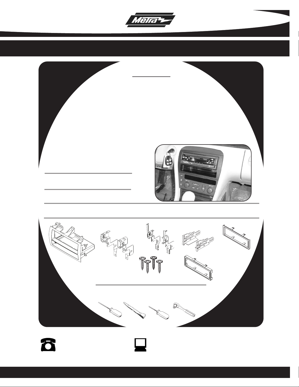
INSTALLATION INSTRUCTIONS FOR PART 99-2005
APPLICATIONS
CADILLAC
ELDORADO 1996-2002
SEVILLE 1996-2005
DEVILLE 2000-2005
DEVILLE CONCOURS (CONSOLE SHIFT)1996-1999
99-2005
KIT FEATURES
• DIN Mount Radio Provision with Pocket
• ISO Mount Radio Provision with Pocket
KIT COMPONENTS
• A) Radio Housing • B) Radio Housing Brackets • C) ISO Brackets • D) ISO Trim Plate • E) Spacer
• F) (4) Phillips Screws
A
98-04S
B
F
TOOLS REQUIRED:
Small Flat Blade Screwdriver • Panel Removal Tool
• Phillips Screwdriver • Socket Wrench
S-E
E
C
D
1-800-221-0932 www.metraonline.com
© COPYRIGHT 2004-2008 METRA ELECTRONICS CORPORATION
Page 2

99-2005
K
NOWLEDGE IS POWER
Enhance your installation and fabrication skills by
enrolling in the most recognized and respected
mobile electronics school in our industry.
Log onto www.installerinstitute.com or call
800-354-6782 for more information and take steps
toward a better tomorrow.
TABLE OF CONTENTS
•
Dash Disassembly
- Cadillac Eldorado 1996-2002------------------------------------- 1
- Cadillac Seville 1996-1997--------------------------------------- 1
- Cadillac Seville 1998-2005--------------------------------------- 2
- Cadillac Deville 2000-2005--------------------------------------- 3
- Cadillac Deville Concours (Console Shift) 1996-1999----------- 2
•
Kit Assembly
- Cadillac Eldorado 1996-2002------------------------------------ 4
- Cadillac Seville 1996-1997--------------------------------------- 4
- Cadillac Seville 1998-2005 --------------------------------------- 5
- Cadillac Deville 2000-2005--------------------------------------- 6
- Cadillac Deville Concours (Console Shift) 1996-1999----------- 5
- DIN Mount Radio Provision --------------------------------------- 7
- ISO Mount Radio Provision--------------------------------------- 7
•
Final Assembly ----------------------------------------------------- 8
*Note: Refer also to the instructions included with the aftermarket radio.
Page 3
99-2005
Rem
ove
3
Ret
ain
ing
Nu
ts
Per
Si
de
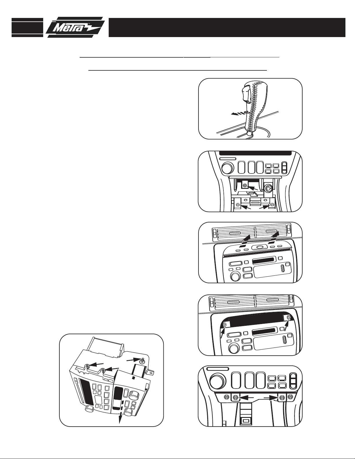
CADILLAC ELDORADO 1996-2002
CADILLAC SEVILLE 1996-1997
Disconnect the negative battery ter-
1
minal to prevent an accidental short
circuit.
Remove C-clip on forward facing side of
2
shift knob and pull and remove knob.
(Figure A)
3
Remove (2) 9/32 screws on each side of
the ashtray assembly and (1) in the middle underneath ashtray insert.
4
Insert a small flat blade screwdriver in
between the radio and the switch panel at
top of radio and pry up and out to remove
switch panel.
(Figure C)
(Figure B)
DASH DISASSEMBLY
A
B
5
Remove (4) 9/32 screws
• (2) from the top
(Figure D) and
C
• (2) from the bottom to remove radio.
(Figure E)
6
Remove the (6) retaining nuts securing
the radio and climate control to the factory bracket assembly and slide the climate
control outward.
(Figure F)
D
Continue to kit assembly
F
E
1
Page 4
99-2005
Rem
ove
3
Ret
ain
ing
Nu
ts
Per
Si
de
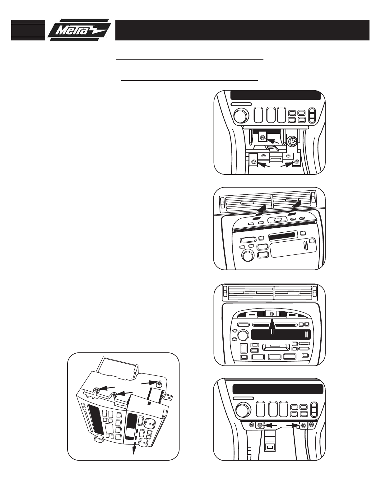
CADILLAC SEVILLE 1998-2005
CADILLAC DEVILLE CONCOURS
(CONSOLE SHIFT) 1996-1999
Disconnect the negative battery ter-
1
minal to prevent an accidental short
circuit.
Remove (2) 9/32 screws on each side of
2
the ashtray assembly and (1) in the middle underneath ashtray insert.
Insert a small flat blade screwdriver in
3
between the radio and the switch panel
at top of radio and pry up and out to
remove switch panel
. (Figure B)
(Figure A)
DASH DISASSEMBLY
A
4
Remove (3) 9/32 screws
• (1) from the top (Figure C) and
• (2) from the bottom to remove radio.
(Figure D)
5
Remove the (6) retaining nuts securing
the radio and climate control to the factory bracket assembly and slide the climate control outward.
(Figure E)
Continue to kit assembly
E
B
C
D
2
Page 5

99-2005
CADILLAC DEVILLE 2000-2005
Disconnect the negative battery ter-
1
minal to prevent an accidental short
circuit.
Unsnap and remove panel surrounding
2
climate controls and radio.
3
Depress clips on both sides of radio and
pull out to remove. (Figure B)
Continue to kit assembly
(Figure A)
DASH DISASSEMBLY
A
B
3
Page 6

99-2005
S-E
S-E
D
D
D
D
98-
04
S
98-
04 S
98-
04
S
CADILLAC ELDORADO 1996-2002
CADILLAC SEVILLE 1996-1997
1
Remove all tabs except the ones marked
S-E from the radio housing. (Figure A)
Slide the S-E radio housing bracket onto
2
the 99-2005 until side clips engage.
(Figure B)
Slide the climate control assembly into
3
the bracket / housing assembly and
attach with the factory hardware.
(Figure C)
KIT ASSEMBLY
A
B
Continue to kit assembly
C
4
Page 7

99-2005
S-E
S
-E
D
D
D
D
98-
04
S
98-
04 S
98-
04
S
KIT ASSEMBLY
CADILLAC SEVILLE 1998-2005
CADILLAC DEVILLE CONCOURS
(CONSOLE SHIFT) 1996-1999
NOTE: In order to DIN mount in the 2000-2004 Deville you will need to use the provided
spacer as described below. There is not enough depth to ISO mount or DIN mount without
the spacer.
Remove all tabs except the ones marked
1
98-04 S from the radio housing.
(Figure A)
Slide the 98-04 S radio housing bracket
2
onto the 99-2005 until side clips engage.
(Figure B)
A
Slide the climate control assembly into
3
the bracket / housing assembly and
attach with the factory hardware.
(Figure C)
4
When DIN mounting slide the included
B
spacer onto the DIN cage that came with
your aftermarket radio before inserting it
into the housing.
(Figure D)
Continue to kit assembly
D
C
5
Page 8

99-2005
S-E
S
-E
D
D
D
D
98-
04
S
98-
04 S
98-
04
S
KIT ASSEMBLY
CADILLAC DEVILLE 2000-2005
NOTE: In order to DIN mount in the 2000-2004 Deville you will need to use the provided
spacer as described below. There is not enough depth to ISO mount or DIN mount without
the spacer.
Remove all tabs except the ones marked
1
D from the radio housing. (Figure A)
When DIN mounting slide the included
2
spacer onto the DIN cage that came with
your aftermarket radio before inserting it
into the housing.
When installing the 99-2005 housing into
3
(Figure B)
the sub dash, use the supplied (4) phillips
screws and mount in the locations shown
(Figure C)
A
B
Continue to kit assembly
C
6
Page 9

99-2005
KIT ASSEMBLY
DIN HEAD UNIT PROVISION
NOTE: Refer also to the instructions included with the aftermarket radio.
1
Slide the DIN cage into the Radio
Housing and secure by bending the
metal locking tabs down.
2
Slide the after-market head unit into
the cage and secure.
Continue to kit assembly
(Figure A)
(Figure B)
A
B
7
Page 10

99-2005
KIT ASSEMBLY
ISO DIN HEAD UNIT PROVISION
NOTE: Refer also to the instructions included with the aftermarket radio.
1
Mount the ISO brackets to the aftermarket radio with the screws
supplied with the unit.
2
Slide the after-market radio unit into
the cage and secure.
Snap the Trim plate into the Radio
3
Housing.
(Figure B)
(Figure A)
(Figure B)
A
Continue to kit assembly
B
8
Page 11

99-2005
FINAL ASSEMBLY
FINAL ASSEMBLY
Locate the factory wiring harness in the dash and make the connection as shown.
1
Metra recomends using the proper mating adapter and making the connections as
shown. (Isolate and individually tape off the ends of any unused wires to prevent
electrical short circuit.)
Re-connect the negative battery terminal and test the unit for proper operation.
2
3
Reassemble radio and dash assemblies in reverse order of disassembly.
FINAL WIRING CONNECTIONS
Make wiring connections using the EIA color code chart shown below and the instructions included with the head
unit. Metra recommends making connections as shown below; Strip, Splice, Solder, Tape. Isolate and individually
tape off ends of any unused wires to prevent electrical short circuit.
A
B
C
D
A) Strip wire ends back 1/2"
B) Twist ends together
C) Solder
D) Tape
METRA / EIA WIRING CODE
12V Ignition / Acc . . . Red
12V Batt / Memory . . Yellow
Ground . . . . . . . . . . . Black*
Power Antenna . . . . . Blue
Amp Turn-On . . . . . . Blue / White
Right Front (+) . . . . . Gray
Right Front (-) . . . . . . Gray / Black
Left Front (+) . . . . . . White
Left Front (-) . . . . . . . White / Black
Right Rear (+). . . . . . Violet
Amp Ground . . . . . . . Black / White
Illumination. . . . . . . . Orange
Dimmer . . . . . . . . . . Orange / White
*NOTE: When Black a wire is not present, ground radio to vehicle chassis.
All colors may not be present on all leads due to manufacturer’s specifications.
Right Rear (-) . . . . . . Violet / Black
Left Rear (+). . . . . . . Green
Left Rear (-) . . . . . . . Green / Black
9
Page 12

99-2005 INSTRUCTIONS
1-800-221-0932 www.metraonline.com
. 10-27-08 © COPYRIGHT 2004-2008 METRA ELECTRONICS CORPORA
Rev
TION INST99-2005
 Loading...