

Page 1

INSTALLATION INSTRUCTIONS FOR PART 99-1003
APPLICATIONS
KIA
Rio 2001
Sephia 1995-2001
Spectra 2000-2001
Sportage 1995-2003
99-1003
KIT FEATURES
• DIN Radio Provision
KIT COMPONENTS
A) Radio Housing #1 • B) Radio Housing #2 • C) Mounting Brackets • D) (4) Captive Studs
• E) (4) Pal Nuts
A
E
Panel Removal Tool • Cutting Tool • Phillips Screwdriver
1-800-221-0932
© COPYRIGHT 2004-2009 METRA ELECTRONICS CORPORATION
B
WIRING
(Sold Separately)
• 70-1003 - KIA Harness 1995-02
• Antenna Adapter N/R
TOOLS REQUIRED:
C
AND ANTENNA CONNECTIONS
www.metraonline.com
D
Page 2

99-1003
TABLE OF CONTENTS
Dash Disassembly
- Kia Rio 2001 .................................................. .1
- Sephia 1995-1997 ...............................................2
- Sephia 1998-2001 ...............................................3
- Spectra 2000-2001...............................................3
- Sportage 1995-1997 .............................................4
- Sportage 1998-2000 .............................................5
- Sportage 2001-2003 . . . . . . . ......................................6
Kit Assembly
- Kit Assembly Preparation .........................................7
- DIN Radio Provision .............................................8
Final Assembly . . . . . . . . . . . . . . . . . . . . . . . . . . . . . . . . . . . . . . . . . . 9
*Note:
Refer also to the instructions included with the aftermarket radio.
Page 3
99-1003 DASH DISASSEMBLY
A/C
OFF
A/
OFF
A/
C
O
FF
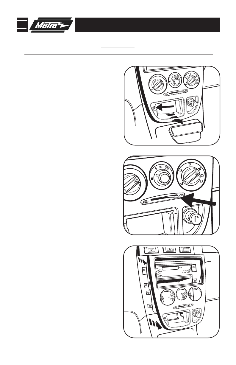
RIO 2001
*
Note: Refer also to the instructions included with the aftermarket radio.
A
Disconnect the negative battery-
1
terminal to prevent an accidental
short circuit.
Remove ashtray and (1) Phillips
2
head screw inside ashtray cavity.
(Figure A)
Remove knob from climate control
3
slide lever.
Unsnap and remove radio/climate
4
control trim panel.
Remove (4) Phillips head screws
5
securing the radio. Unplug and
remove the radio.
Continue to kit preparation.
(Figure B)
(Figure C)
B
C
1
Page 4
99-1003 DASH DISASSEMBLY
SEPHIA 1995-1997
*
Note: Refer also to the instructions included with the aftermarket radio.
Disconnect the negative battery
1
terminal to prevent an accidental
short circuit.
Remove plastic screw cover to the
2
left of the coin tray and remove the
Phillips head screw from behind
cover.
Remove switch blank to the far
3
right of the switch panel and
remove the Phillips head screw
from behind switch blank.
Unclip and remove dash trim
4
panel.
Remove (4) Phillips head screws
5
securing the radio. Unplug and
remove the radio.
Continue to kit preparation.
2
Page 5

99-1003 DASH DISASSEMBLY
SEPHIA 1998-2001
SPECTRA 2000-2001
*
Note: Refer also to the instructions included with the aftermarket radio.
Disconnect the negative battery
1
terminal to prevent an accidental
short circuit.
Remove (1) Phillips head screw
2
from above instrument cluster.
Unclip and remove dash trim
3
panel.
Remove (4) Phillips head screws
4
securing the radio. Unplug and
remove the radio.
Continue to kit preparation.
3
Page 6

99-1003 DASH DISASSEMBLY
SPORTAGE 1995-1997
*
Note: Refer also to the instructions included with the aftermarket radio.
Disconnect the negative battery
1
terminal to prevent an accidental
short circuit.
Remove ashtray and (2) Phillips
2
head screws inside ashtray cavity.
Unclip and remove dash trim panel.
3
Remove (4) Phillips head screws
4
securing the radio. Unplug and
remove the radio.
Continue to kit preparation.
4
Page 7

99-1003 DASH DISASSEMBLY
SPORTAGE 1998-2000
*
Note: Refer also to the instructions included with the aftermarket radio.
Disconnect the negative battery
1
terminal to prevent an accidental
short circuit.
Unclip and remove dash trim panel.
2
Remove (4) Phillips head screws
3
securing the radio. Unplug and
remove the radio.
Continue to kit preparation.
5
Page 8

99-1003 DASH DISASSEMBLY
SPORTAGE 2001-2003
*
Note: Refer also to the instructions included with the aftermarket radio.
Disconnect the negative battery
1
terminal to prevent an accidental
short circuit.
Unclip and remove climate con-
2
trol/vent trim panel.
Remove screw covers from trim
3
panel below steering column and
remove screws from behind covers. Lower the trim panel (it is not
necessary to remove the panel).
(Figure B)
Remove (3) Phillips head screws
4
from bottom of steering column
housing and remove both upper
and lower sections of housing.
Remove (1) Phillips head screw
5
from outside left edge of dash and
(2) Phillips head screws from near
hood release.
(Figure A)
(Figure C)
A
B
C
Loosen nut behind hood release
6
and remove lower left side dash
(Figure C)
trim.
Remove (4) Phillips head screws
7
from instrument trim panel and
remove panel.
Remove (4) Phillips head screws
8
securing the radio. Unplug and
remove the radio.
Continue to kit assembly.
(Figure D)
D
6
Page 9

99-1003 KIT PREPARATION
"B"
"B"
"A"
"A"
"B"
"B"
"B"
"B"
"B"
"B"
"A"
"A"
"A"
"A"
"A"
"A"
KIT ASSEMBLY PREPARATION
*
Note: Refer also to the instructions included with the aftermarket radio.
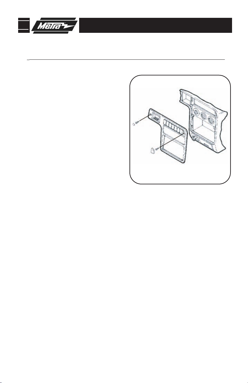
RIO 2001
SEPHIA 1995-1997
Cut and remove mounting tabs “B”
from Radio Housing #2. (The tabs can
be identified by the letter stamped on
the back of each tab.)
(Figure A)
A
SPORTAGE 1995-1997
Cut and remove mounting tabs “A” from
Radio Housing #2 and the mounting
brackets. (The tabs can be identified by
the letter stamped on the back of each
tab.) Locate the scored line on the back
of the radio housing and break away
the bottom portion of the housing as
shown.
(Figure C)
SEPHIA 1998-2001
SPECTRA 2000-2001
Cut and remove mounting tabs “B”
from Radio Housing #1. (The tabs can
be identified by the letter stamped on
the back of each tab.)
(Figure B)
B
SPORT
AGE 1998-2003
Cut and remove mounting tabs “A” from
Radio Housing #1. Cut and remove tabs
“B” from the mounting brackets. (The
tabs can be identified by the letter
stamped on the back of each tab.)
(Figure D)
C
Continue to kit assembly.
D
7
Page 10

99-1003 KIT ASSEMBLY
DIN MOUNT RADIO
*
Note: Refer also to the instructions included with the aftermarket radio.
NOTE: For Sportage 1995-97 and
1998-03 secure the Mounting
Brackets to the Radio Housing with
(4) Captive Studs and (4) Pal Nuts.
(Figure A)
Slide the DIN cage into the radio
1
housing and secure by bending the
metal locking tabs outward.
(Figure B)
Slide the radio into the DIN
2
cage/housing assembly until it
snaps into place.
Continue to final assembly.
B
(Figure C)
A
C
8
Page 11

99-1003 FINAL ASSEMBLY
FINAL ASSEMBLY
A
(A) Strip wire ends back 1/2"
B
B) Twist ends together
C) Solder
C
D
Locate the factory wiring harness in the dash. Metra recommends using the
1
proper mating adapter and making connections as shown. (Isolate and individually tape off the ends of any unused wires to prevent electrical short circuit.)
Re-connect the negative battery terminal and test the unit for proper operation.
2
Reassemble radio and dash assemblies in reverse order of disassembly.
3
D) Tape
FINAL WIRING CONNECTIONS
Make wiring connections using the EIA color code chart shown below and the instructions included with the
head unit. Metra recommends making connections as shown below; Strip, Splice, Solder, Tape. Isolate and
individually tape off ends of any unused wires to prevent electrical short circuit.
METRA / EIA WIRING CODE
12V Ignition / Acc . . . . . . . . . . Red
12V Batt / Memory. . . . . . . . . Yellow
Ground. . . . . . . . . . . . . . . . . . Black*
Power Antenna. . . . . . . . . . . . Blue
Amp Turn-On . . . . . . . . . . . . . Blue / White
Amp Ground. . . . . . . . . . . . . . Black / White
Illumination . . . . . . . . . . . . . . Orange
Dimmer . . . . . . . . . . . . . . . . . Orange / White
Right Front (+) . . . . . . . . . . . . Gray
Right Front (-). . . . . . . . . . . . . Gray/ Black
Left Front (+) . . . . . . . . . . . . . White
Left Front (-). . . . . . . . . . . . . . White / Black
Right Rear (+) . . . . . . . . . . . . Violet
Right Rear (-) . . . . . . . . . . . . . Violet / Black
Left Rear (+) . . . . . . . . . . . . . Green
Left Rear (-) . . . . . . . . . . . . . . Green / Black
*NOTE: When a Black wire is not present, ground radio to vehicle chassis.
All colors may not be present on all leads due to manufacturer’s specifications.
9
Page 12

99-1003 INSTRUCTIONS
1-800-221-0932
Rev. 04/13/09 © COPYRIGHT 2004-2009 METRA ELECTRONICS CORPORATION INST99-1003
www.metraonline.com
 Loading...