

Page 1
INSTALLATION INSTRUCTIONS FOR PART 95-8904BINSTALLATION INSTRUCTIONS FOR PART 95-8904B
APPLICATIONS
SUBARU
LEGACY & OUTBACK
2010
(non-NAV models)
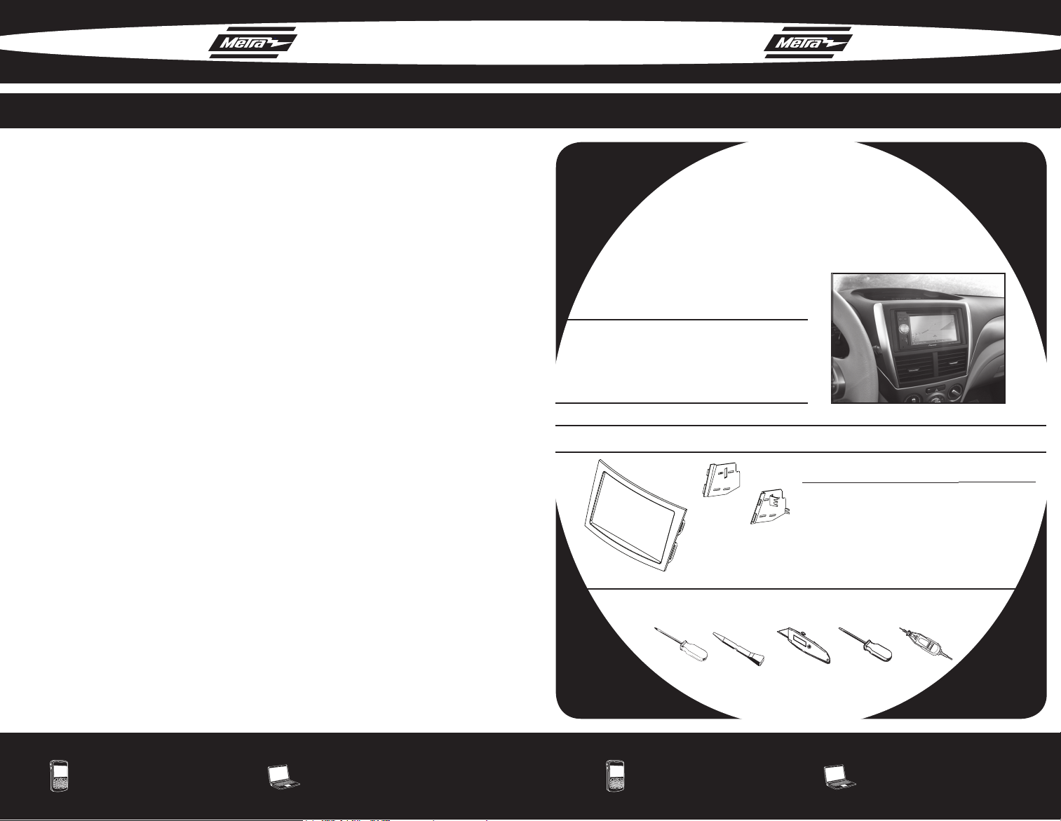
95-8904B
KIT FEATURES
• DDIN radio provision
• ISO stacked provision
• Painted scratch resistant matte black
Note: Minor sub-dash modications required. Part
# 95-8903B does not require these modications.
KIT COMPONENTS
• A) DDIN Trim Plate • B) DDIN Brackets
REV. 2/03/2010
METRA. THE WORLD’S BEST KITS.™
1-800-221-0932 metraonline.com
© COPYRIGHT 2004-2010 METRA ELECTRONICS CORPORATION
A
B
WIRING & ANTENNA CONNECTIONS (SOLD SEPARATELY)
• 70-8901 Subaru Harness 1990-UP
• 70-7552 Nissan Harness 2007-UP
• 40-SB10 Subaru Antenna Adapter 2005-UP
TOOLS REQUIRED
• Phillips Screwdriver • Panel Removal Tool • Utility Knife
• Small Flat Blade Screwdriver • Hacksaw (or similar cutting tool)
METRA. THE WORLD’S BEST KITS.™
1-800-221-0932 metraonline.com
© COPYRIGHT 2004-2010 METRA ELECTRONICS CORPORATION
Page 2

KNOWLEDGE IS POWER
Enhance your installation and fabrication skills by
enrolling in the most recognized and respected
mobile electronics school in our industry.
Log onto www.installerinstitute.com or call
800-354-6782 for more information and take steps
toward a better tomorrow.
95-8904B 95-8904B
TABLE OF CONTENTS
DASH DISASSEMBLY
• 2010 SUBARU LEGACY/OUTBACK . . . . . . . . . 1
KIT ASSEMBLY
• 2010 SUBARU LEGACY/OUTBACK
• DDIN / STACKED ISO HEAD UNIT PROVISION. . 2
*NOTE: Refer Also to the instructions included with the aftermarket radio.
NOTES
Metra recommends MECP certified
technicians
Page 3

95-8904B
95-8904B DASH DISASSEMBLY
NOTES
2010 SUBARU LEGACY / OUTBACK
Disconnect the negative battery
1
terminal to prevent an accidental
short circuit.
Unclip and remove the radio trim
2
panel including the a/c vents.
(Fig. A)
Remove (4) Phillips screws securing
3
the factory radio.
A
1
Continue to Kit Assembly
Page 4

95-8904B KIT ASSEMBLY
95-8904B
2010 SUBARU LEGACY / OUTBACK
DDIN / STACKED ISO
HEAD UNIT PROVISION
Locate the factory wiring harness
1
in the dash. Metra recommends
using the proper mating adapters
from Metra and AXXESS to integrate your new radio. Re-connect
the negative battery terminal and
test the unit for proper operation.
Attach the Double DIN brackets to
2
the Double DIN trim plate. (Fig. A)
Slide the Double DIN head unit or
3
stacked ISO head units into the
bracket/radio housing assembly
and secure the Double DIN head
unit or stacked ISO head units to
the assembly using the screws
supplied with the radio. (Fig. B)
Using an air saw, hacksaw, or simi-
4
lar cutting tool, cut to the inside of
the radio’s lower mounting holes,
through the plastic and metal
bracket. (Cut on the inside of each
hole as close to the hole as you
can get. If cut properly you may reuse two bottom factory screws, if
not use self tapping screws on the
bottom.) (Fig. C)
A
B
C
NOTES
Reassemble dash in reverse order
5
of disassembly.
2
 Loading...