

Page 1
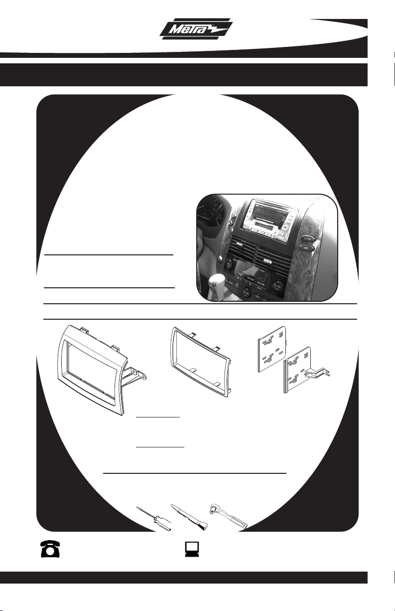
INSTALLATION INSTRUCTIONS FOR PART 95-8208
APPLICATIONS
Toyota Sienna
2004-2010
95-8208
KIT FEATURES
• Double DIN Radio Provision
• Stacked ISO Mount Units Provision
KIT COMPONENTS
• A) Radio Housing • B) Double Din Trim Plate • C) Double DIN Brackets
A
B
WIRING AND ANTENNA CONNECTIONS (Sold Separately)
Wiring Harness:
• 70-1761 -Toyota harness 1987-up
• TYTO-01 - Toyota amp harness 2003-up
Antenna Adapter:
• Not required
TOOLS REQUIRED:
Small Flat Blade Screwdriver/ Panel Removal Tool
• Socket Set
1-800-221-0932
© COPYRIGHT 2007-2010 METRA ELECTRONICS CORPORATION
www.metraonline.com
C
Page 2

95-8208
TABLE OF CONTENTS
Dash Disassembly
-
Toyota Sienna 2004-2010 . . . . . . . . . . . . . . . . . . . . . .
. . . . . . 1
Kit Assembly
- Double DIN Radio Provision . . . . . . . . . . . . . . . . . . . . . . . . . . . . . . . . 2
- Stacked ISO Mount Units Provision . . . . . . . . . . . . . . . . . . . . . . . . . . 3
Final
Assembly . . . . . . . . . . . . . . . . . . . . . . . . . . . . . . . . . . . . . . . . . . . 4
*Note:
Refer also to the instructions included with the aftermarket radio.
Page 3
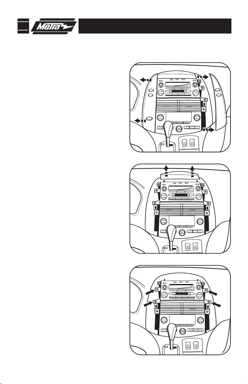
95-8208 DASH DISASSEMBLY
Toyota Sienna 2004-2010
1
Disconnect the negative battery terminal to prevent an accidental short
circuit.
Unclip and remove panels from left
2
and right side of radio. (
Unclip and remove panel or speaker
3
cover above radio.
Remove (4) 10 MM bolts securing the
4
radio. Unplug and remove the radio.
(Figure C)
Continue to final assembly.
Figure A)
(Figure B)
A
B
C
1
Page 4
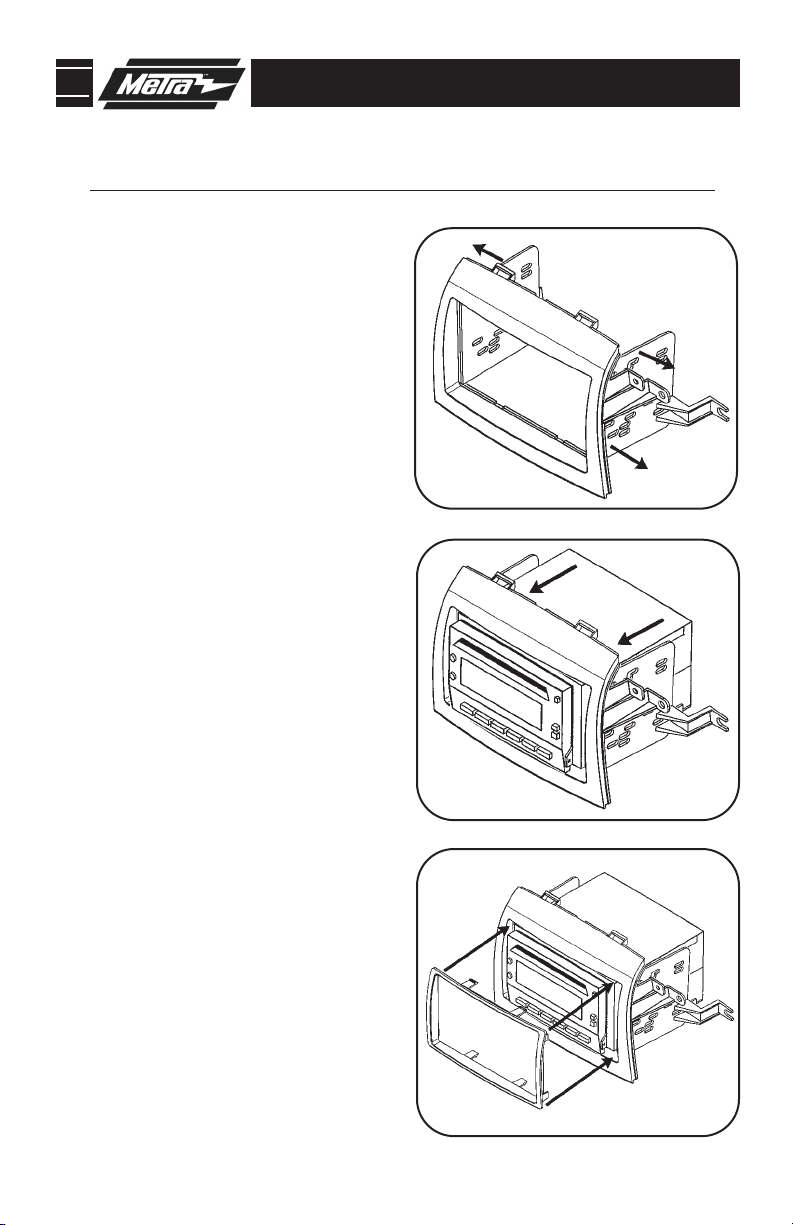
95-8208 KIT ASSEMBLY
DOUBLE DIN RADIO PROVISION
*Note: Refer also to the instructions included with the aftermarket radio.
A
1
Snap the Double DIN brackets to the
inside edge of the radio housing.
(Figure A)
2
Slide the Double DIN radio into the
bracket/housing assembly and secure
the radio to the assembly using the
screws supplied with the radio.
(Figure B)
3
Snap the Double DIN Trim plate into
the Radio Housing.
Continue to final assembly.
(Figure C)
B
2
C
Page 5

95-8208 KIT ASSEMBLY
STACKED ISO UNITS PROVISION
*Note: Refer also to the instructions included with the aftermarket radio.
A
1
Snap the Double DIN brackets to the
inside edge of the radio housing.
(Figure A)
2
Slide the stacked ISO units into the
bracket/housing assembly and secure
the units to the assembly using the
screws supplied with the units.
(Figure B)
3
Snap the Double DIN Trim plate into
the Radio Housing.
Continue to final assembly.
(Figure C)
B
3
C
Page 6
95-8208 FINAL ASSEMBLY
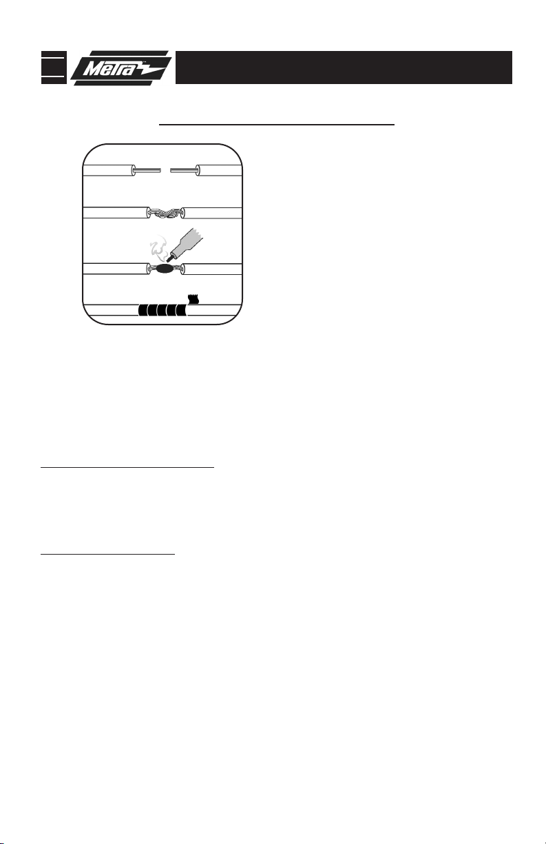
FINAL ASSEMBLY
A
(A) Strip wire ends back 1/2"
B
B) Twist ends together
C) Solder
C
D
Locate the factory wiring harness in the dash. Metra recommends using the
1
proper mating adapter and making connections as shown. (Isolate and individually tape off the ends of any unused wires to prevent electrical short circuit.)
Re-connect the negative battery terminal and test the unit for proper operation.
2
Reassemble radio and dash assemblies in reverse order of disassembly.
3
D) Tape
FINAL WIRING CONNECTIONS
Make wiring connections using the EIA color code chart shown below and the instructions included with the
head unit. Metra recommends making connections as shown below; Strip, Splice, Solder, Tape. Isolate and
individually tape off ends of any unused wires to prevent electrical short circuit.
METRA / EIA WIRING CODE
12V Ignition / Acc . . . . . . . . . . Red
12V Batt / Memory. . . . . . . . . Yellow
Ground. . . . . . . . . . . . . . . . . . Black*
Power Antenna. . . . . . . . . . . . Blue
Amp Turn-On . . . . . . . . . . . . . Blue / White
Amp Ground. . . . . . . . . . . . . . Black / White
Illumination . . . . . . . . . . . . . . Orange
Dimmer . . . . . . . . . . . . . . . . . Orange / White
Right Front (+) . . . . . . . . . . . . Gray
Right Front (-). . . . . . . . . . . . . Gray/ Black
Left Front (+) . . . . . . . . . . . . . White
Left Front (-). . . . . . . . . . . . . . White / Black
Right Rear (+) . . . . . . . . . . . . Violet
Right Rear (-) . . . . . . . . . . . . . Violet / Black
Left Rear (+) . . . . . . . . . . . . . Green
Left Rear (-) . . . . . . . . . . . . . . Green / Black
*NOTE: When a Black wire is not present, ground radio to vehicle chassis.
All colors may not be present on all leads due to manufacturer’s specifications.
4
Page 7

95-8208
NOTES
5
Page 8

95-8208 INSTRUCTIONS
1-800-221-0932
REV. 04/27/10 © COPYRIGHT 2004-2010 METRA ELECTRONICS CORPORATION INST95-8208
www.metraonline.com
 Loading...